全文HTML
--> --> -->近年来, 学界提出了几种拓展相控阵列扫描范围的方法. 第一种方法是利用方向图可重构天线单元作为阵元[2-7]. 天线单元的3-dB波束宽度并不是非常宽, 但是可以通过改变天线单元辐射方向图进行波束切换, 进而实现宽角扫描.同时, 学界对于方向图可重构磁电偶极子天线单元进行了深入研究, 如H面波束宽度可重构磁电偶极子天线[8,9], 双面波束宽度可重构磁电偶极子天线[10]. 上述波束宽度可调的磁电偶极子天线在宽角扫描阵列的设计中应用前景广阔. 然而, 这类天线单元引入了额外的电子元件及控制电路, 从而增加了设计难度, 并对辐射方向图产生了不良影响.
与利用方向图可重构天线单元作为阵元不同, 另一类拓展相控阵列天线扫描范围的方法是采用宽波束天线单元作为阵元. 学界提出了多种拓展天线单元3-dB波束宽度的方法[11-19], 如新型微带磁偶极子天线[14]、 采用寄生像素层[15]以及使用电壁[16,17]. 值得注意的是, 文献[12]将常见的载体天线分为八类并指出了具有宽角扫描应用潜力的天线单元类型, 从而为设计宽波束天线提供了指导思路. 采用宽波束天线作为阵元使得阵列天线旁瓣水平升高, 文献[20]中的布阵策略可为解决这些问题提供参考.
常见的拓展相控阵列天线扫描范围的方法还包括利用梯度超表面[21]作为阵列覆层. 当阵列发射电磁波透过特定设计的梯度超表面时, 波束偏转至更低角域, 从而拓展了阵列扫描范围.
就上述文献而言, 大多数研究集中于某个频点附近, 也就是说, 所设计的相控阵列天线仅能在点频范围内实现宽角扫描, 而对于能够在宽带范围内实现宽角扫描的相控阵列天线研究不足, 而这也正是实际应用亟需的.
本文设计并测试了两款基于宽波束天线单元的宽角扫描线性阵列. 首先, 通过加载微带磁偶极子的方法拓展了天线单元的3-dB波束宽度. 基于此, 设计了两款9单元一维扫描阵列并进行了加工测试. 仿真和实测结果均表明, 加载的微带磁偶极子有效拓展了天线单元的3-dB波束宽度, 所设计的一维阵列天线具备在宽频带范围内实现宽角扫描的能力.
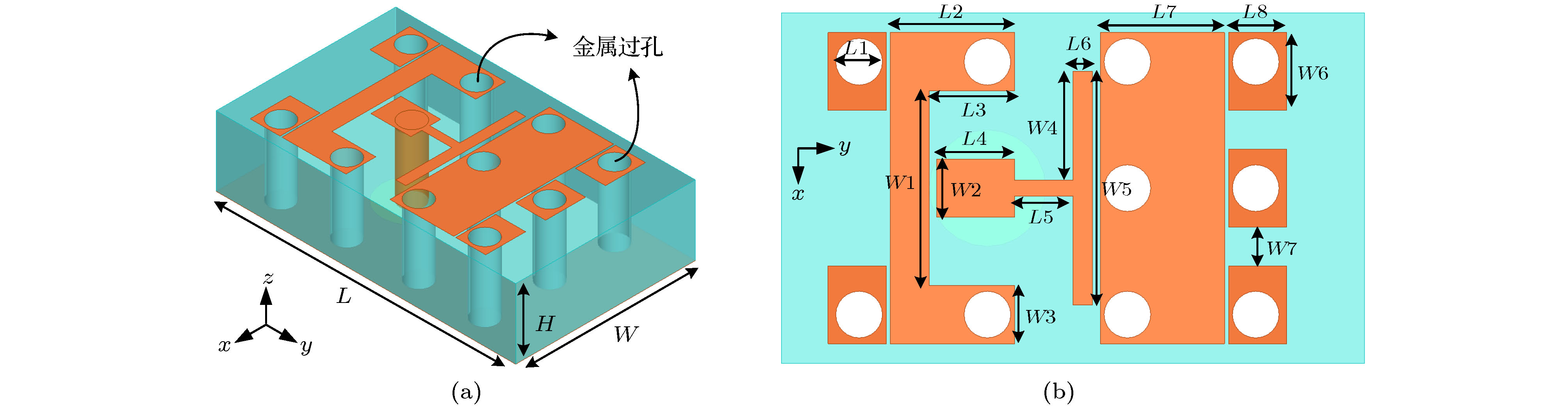 图 1 宽波束天线单元结构图 (a) 三维图; (b) 俯视图
Figure1. Structure of the wide-beam antenna: (a) 3-D view; (b) top view.
| 天线参数 | L | W | H | L1 | L2 | L3 | L4 | L5 | L6 | L7 | L8 | W1 | W2 | W3 | W4 | W5 | W6 | W7 |
| 参数值/mm | 15 | 9 | 3.5 | 0.6 | 3.2 | 2.2 | 2 | 1.5 | 0.5 | 3.2 | 1.5 | 5 | 1.5 | 1.5 | 2.8 | 6 | 2 | 1 |
表1宽波束天线单元参数
Table1.Parameters of the wide-beam antenna.
天线单元的宽带特性是宽带阵列的前提. 文献[23]中提出的磁电偶极子天线是一款结构简单、辐射性能稳定的宽带天线. 天线单元的宽波束特性可通过加载微带磁偶极子实现. 图2展示了宽波束天线单元的设计流程. 首先, 改变了文献[22]中天线的尺寸, 使其工作于X波段, 得到1号天线. 然后, 改变了1号天线的馈电结构及电偶极子的形状以获得更好的阻抗匹配特性, 得到2号天线. 利用电磁仿真软件Ansys HFSS对2号天线单元进行仿真, 计算其波束宽度.图3给出了其在10 GHz下的辐射方向图. 由图3可知, 2号天线单元E面方向图3-dB波束宽度仅为82.3°, 未能达到希望的波束宽度100°, 不能满足宽角扫描相控阵列天线的设计要求. 为拓展天线波束宽度, 在电偶极子两侧加载了微带磁偶极子. 由图3可得, 加载微带磁偶极子的3号天线, 其E面3-dB波束宽度由82.3°拓宽至115.8°, H面3-dB波束宽度由119.8°拓宽至185.2°.
 图 2 设计流程
Figure2. The design process.
 图 3 10 GHz处3-dB波束宽度拓展效果
Figure3. The broadening effect of 3-dB beam-width at 10 GHz.
图4给出了3号天线单元10 GHz处一个周期内的表面电流分布图. 由图4可知, 新增加的金属化过孔表面电流与同侧原有金属过孔表面电流方向相同, 从而在原有等效磁流M2的基础上增加了两个等效磁流M1和M3
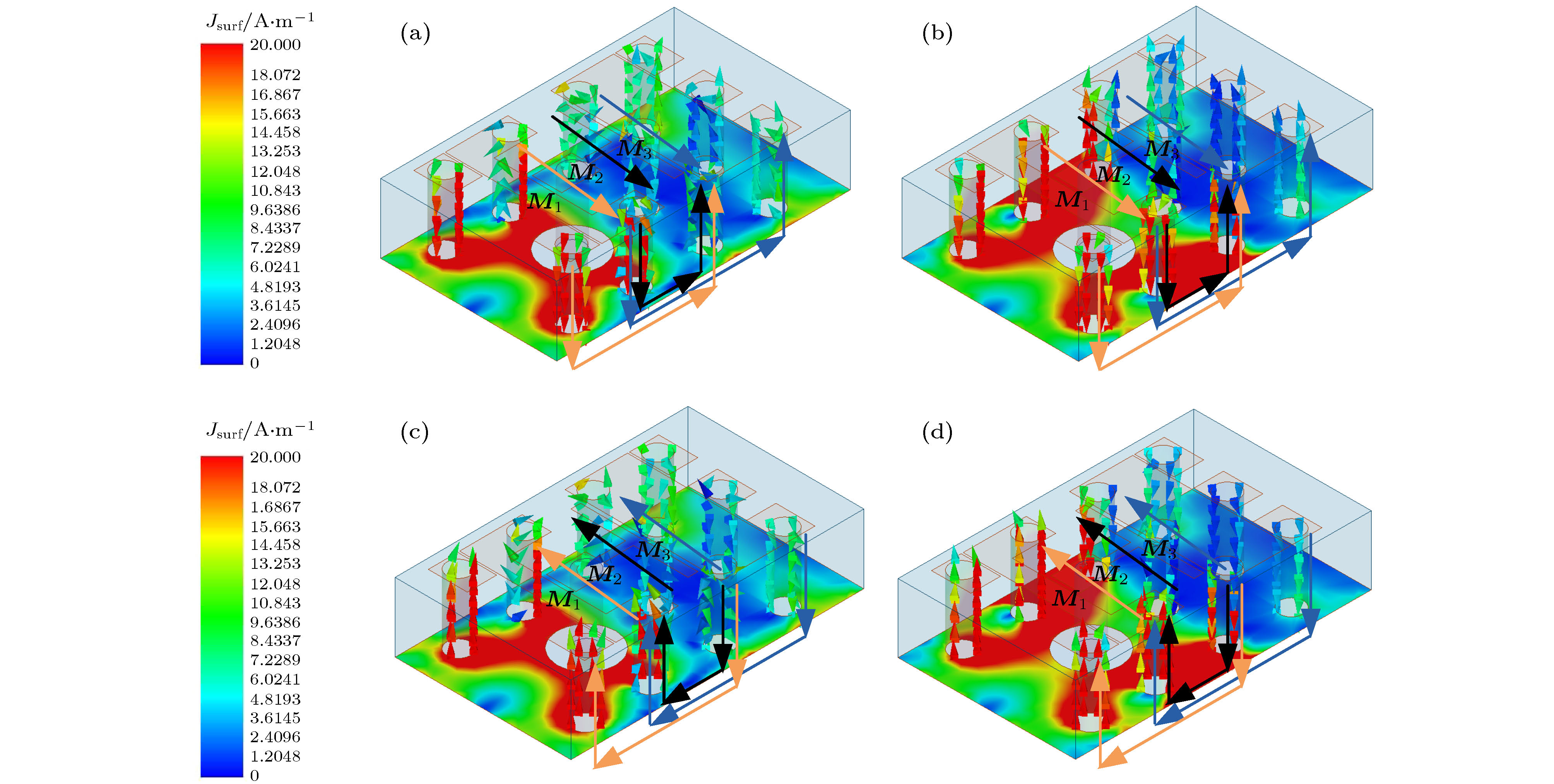 图 4 10 GH处电流分布图 (a) 0°; (b) 90°; (a) 180°; (b) 270°
Figure4. The distribution of electric current at 10 GHz: (a) 0°; (b) 90°; (c) 180°; (d) 270°.
图5给出了设计的宽波束天线单元的驻波比. 由图5可得, 设计的天线单元在7.3—12.6 GHz驻波比小于2, 相对阻抗带宽为53.26%. 图6给出了设计的宽波束天线单元在7—12 GHz的辐射方向图, 表2给出了天线单元在该频带范围内的3-dB波束宽度. 由表2可得, 天线单元的E面方向图3-dB波束宽度在9—12 GHz均大于107°, H面方向图3-dB波束宽度在9—GHz均大于178°. 综合驻波比及3-dB波束宽度来看, 提出的天线单元已满足宽带宽角扫描相控阵列对于天线单元的设计要求. 然而, 波束展宽后, 天线单元的增益下降. 表3给出了参考天线及波束展宽后天线的增益数值.
| 频率/GHz | E面3-dB波束宽度/(°) | H面3-dB波束宽度/(°) |
| 7 | 97 | 180.4 |
| 8 | 101.1 | 178.2 |
| 9 | 107 | 178.4 |
| 10 | 115.8 | 185.2 |
| 11 | 135.5 | 220.9 |
| 12 | 180.6 | 360 |
表2天线单元3-dB波束宽度
Table2.3-dB beam-width of the antenna.
| 频率/GHz | 参考天线增益/dBi | 本文天线增益-/dBi |
| 9 | 5.91 | 4.19 |
| 10 | 5.98 | 3.91 |
| 11 | 5.84 | 3.59 |
| 12 | 5.43 | 2.87 |
表32号天线与3号天线增益对比
Table3.Comparison between Ant.2 and Ant.3.
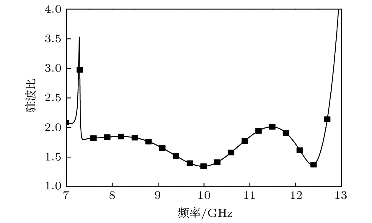 图 5 天线单元驻波比
Figure5. VSWR of the antenna.
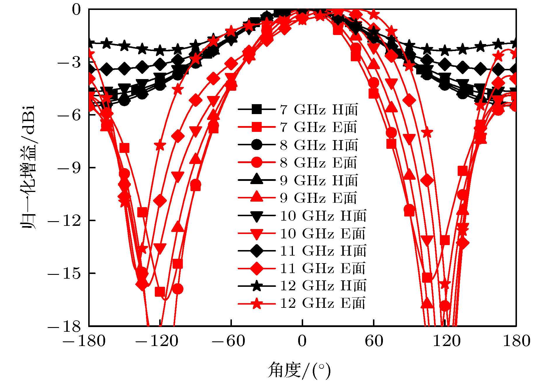 图 6 天线单元方向图
Figure6. Radiation patterns of the antenna.
将所提出的天线和目前已有的具有宽波束特性的磁电偶极子天线进行了对比(表4), 由表4可得, 本文所设计的磁电偶极子天线主要优势在于双面宽波束特性、宽带特性及低剖面特性.
| 文献 | 相对阻抗带宽/% | 工作频带/GHz | 增益/dBi | 剖面/λ | E面波束宽度/(°) | H面波束宽度/(°) |
| [16] | 34.6 | 3.1—4.4 | — | 0.21 | 174 | 112 |
| [17] | 81.1 | 3.3—7.8 | 3.65 ± 1.65 | 0.27 | 215 (5.5 GHz) 106 (7.5 GHz) | 186 (5.5 GHz) 83 (7.5 GHz) |
| [24] | 41 | 2.42—3.7 | 6.3 | 0.45 | 75 | 120 |
| [25] | 63 | 2.76—5.3 | 5 | 0.15 | 129.1 (3.4 GHz) 151.6 (4.9 GHz) | 100.4 (3.4 GHz) 94.2 (4.9 GHz) |
| [26] | 22.6 19.6 | 3.25—4.08 4.29—5.22 | 6.9 ± 0.3 5.4 ± 0.7 | 0.27 0.23 | 91 (3.5 GHz) 168 (4.9 GHz) 83 (3.5 GHz) 74 (4.9 GHz) | 83 (3.5 GHz) 162 (4.9 GHz) 90 (3.5 GHz) 133 (4.9 GHz) |
| 本文 | 53.26 | 7.3—12.6 | 3.53 ± 0.66 | 0.116 | >97 | >178.2 |
表4已报道宽波束磁电偶极子天线与本文天线特性对比
Table4.Comparison between the reported and proposed magneto-electric dipole antenna.
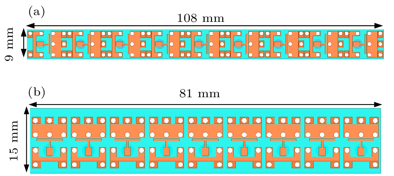 图 7 一维相控阵列 (a) E面阵列; (b) H面阵列
Figure7. The phased arrays: (a) E-plane array; (b) H-plane array.
 图 8 阵列实物图 (a) E面阵列; (b) H面阵列
Figure8. The prototypes of the arrays: (a) E-plane array; (b) H-plane array.
阵列中心单元的有源驻波比由安捷伦N5230 C矢量网络分析仪测试得到, 阵列的扫描方向图通过合成阵列中所有阵元的有源方向图得到, 因此, 实际测量过程中没有用到移相器及馈电网络, 仅通过微波暗室中的远场方向图测量系统测量得到了阵列中每一天线单元的有源方向图.
图9给出了阵列中心天线单元的实测有源驻波比. 由图9可得, E面阵列中心单元有源驻波比在9—13 GHz小于2. 与仿真结果相比, 实测有源驻波比在10.3—11 GHz有所抬升, 但仍小于2. H面阵列中心单元的有源驻波比, 而在9.6—12.6 GHz小于2.5, 实测结果与仿真结果吻合较好.
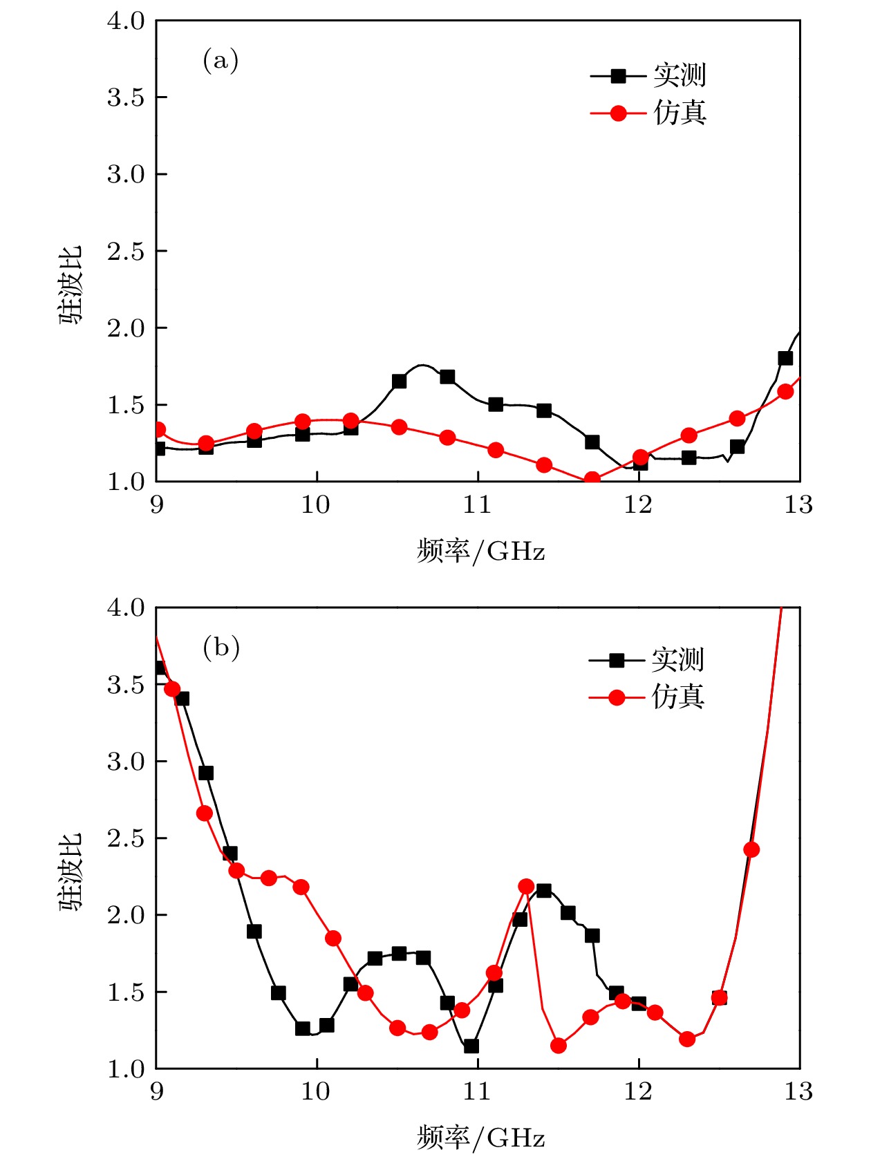 图 9 阵列中心单元实测有源驻波比 (a) E面阵列; (b) H面阵列
Figure9. The active VSWRs of the unit at the center of two arrays: (a) E-plane array; (b) H-plane array.
图10给出了E面阵列的实测扫描方向图. 由图10可得, E面阵列的扫描波束可覆盖 ± 70°的角域范围, 扫描过程中天线增益损耗小于3 dB. 实测结果与仿真结果吻合较好, 验证了E面阵列的扫描性能.
 图 10 E面阵列实测扫描方向图 (a) 9 GHz; (b) 10 GHz; (a) 11 GHz; (b) 12 GHz
Figure10. The scanning patterns of the E-plane array: (a) 9 GHz; (b) 10 GHz; (c) 11 GHz; (d) 12 GHz.
图11给出了H面阵列的实测扫描方向图. 由图11可得, H面阵列的扫描波束可覆盖 ± 90°的角域范围. 扫描过程中天线增益损耗小于2 dB. 实测结果与仿真结果吻合较好, 验证了H面阵列的扫描性能.
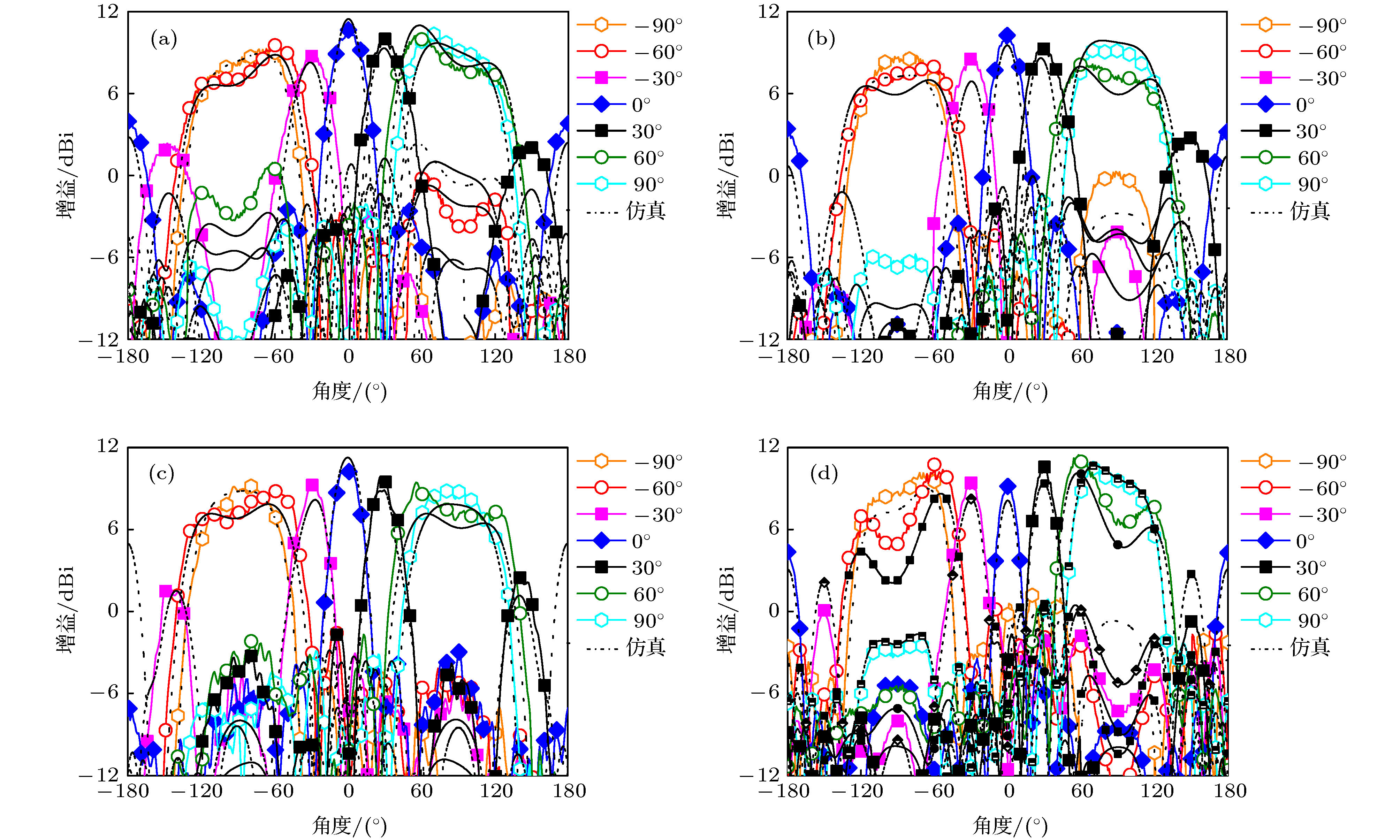 图 11 H面阵列实测扫描方向图 (a) 9 GHz; (b) 10 GHz; (a) 11 GHz; (b) 12 GHz
Figure11. The scanning patterns of the H-plane array: (a) 9 GHz; (b) 10 GHz; (c) 11 GHz; (d) 12 GHz.
将本文提出的相控阵和已发表的代表性X波段相控阵天线的典型指标进行了对比(表5), 由表5可得, 本文所设计的相控阵主要优势在于宽角扫描能力及低剖面特性.
| 文献 | 相对阻抗带宽/% | 工作频带/GHz | 剖面/λ | E面扫描范围/(°) | H面扫描范围/(°) |
| [27] | 40 | 8—12 | 0.31 | ± 60 (8—10 GHz) ± 50 (12 GHz) | ± 60 (8—10 GHz) ± 50 (12 GHz) |
| [28] | 40 | 8—12 | 1.22 | ± 45 | ± 45 |
| [29] | 18.18 | 10.5—12.6 | 0.84 | ± 60 | ± 60 |
| [30] | 40 | 8—12 | 0.8 | ± 45 | ± 60 |
| [31] | 30 | — | — | ± 60 | ± 60 |
| 本文 | 28.5 | 9—12 | 0.116 | ± 70 | ± 90 |
表5已报道X波段相控阵与本文相控阵天线特性对比
Table5.Comparison between the reported and proposed X-band phased arrays.
