1.College of Engineering and Applied Sciences, Nanjing University, Nanjing 210023, China 2.School of Physics, Nanjing University, Nanjing 210023, China
Fund Project:Project supported by the National Natural Science Foundation of China (Grant Nos. 11874214, 11774165, 11574146) and the Natural Science Foundation of Jiangsu Province, China (Grant No. BK20150563)
Received Date:05 September 2019
Accepted Date:10 October 2019
Published Online:05 February 2020
Abstract:The Talbot effect is a near-field diffraction effect that occurs in periodic structures. In a circular periodic structure with a point source as incident light, it has been found that there is no self-imaging effect of the grating at a certain propagation distance. In this paper, we combine the conformal transformation with the Talbot effect and work out a special medium in the physical space, which allows the circular grating to have a Talbot effect within it. The refractive index distribution generated by conformal transformation is calculated and the corresponding self-imaging radius expression is obtained. Lumerical product is used for simulation verification, and the applicable condition of the method is summarized. We separately carry out the simulations of a circular grating with and without the designed medium. Light field distributions in the two simulations differ from each other. The light field in the second situation shares more similarities with the light field of a plane grating than the first simulation. What is more, in the second situation, we can work out a certain Talbot radius, and the light field distribution at the calculated Talbot radius is quite similar to that at the circular grating. But for the first situation, we cannot calculate a certain Talbot radius and can obtain only the radius of the ring with highest self-imaging accuracy by comparing light field at each distance with the grating structure. We find that the small period of the circular grating we used in the second situation makes the light field at Talbot radius furcate. So we carry out a third simulation of a circular grating with a large period compared with the incident wavelength. The self-imaging result matches the grating structure quite well. However, there are some limits in this method. According to the conformal transformation, the refractive index near the center tends to be infinite, so we have to remove the medium near the center. Also, when the radius is big enough, refractive index there can be smaller than 1, so the Talbot effect should happen within this radius. In conclusion, we show that the transformation optics can be introduced into the self-imaging of circular gratings, and thus greatly expanding the range of applications for the Talbot effect. Keywords:Talbot effect/ self-imaging/ circular grating/ conformal transformation
2.理 论对于真空中圆心在原点的环形光栅(图1), 其中虚线圆为环形光栅, 圆心处为点光源, 外围的实线圆代表像面, 在柱坐标系中很容易得到它的傅里叶展开式: 图 1 点光源入射的环形光栅衍射图解 Figure1. Ring grating with a point source of incident light.
由(5)式可以看出, 要存在$m'$满足$R_T<m' $, 所计算的环形光栅的周期数和半径需要满足$m > \sqrt { {{8{{\text{π}}^2}{\rm{e}}{R_0}}}/{\lambda }} $的关系, 这是由于不存在折射率小于1的材料而产生的限制. 取$m'$ = 50 μm, 使用Lumerical对入射光为波长1064 nm的点光源, R0 = 10 μm, m = 50带有折射率渐变层的环形光栅进行了衍射模拟(结果见图4). 其中光栅的内径为10 μm, 外径为10.1 μm. 根据计算, 此光栅的自成像半径应为44.55 μm. 将图2与图4(a)相比较, 可以很明显地观察到折射率渐变层的存在使得光场分布发生了变化, 后者的衍射情况与平面光栅更为类似. 另一方面, 我们发现图4(a)中光场交错的间距在逐渐增大, 这与(5)式中指数的存在相符. 然而, 由图4(b)可以看出, 光栅处的光场有着明显的尖端分叉. 这是由于受到模拟条件的限制, 在模拟中本文的光栅周期较小所造成的, 在实际中若采用的光栅周期大一些, 二者符合的程度能够提升很多. 另外使用同种入射光对于内径为50 μm, 外径为50.1 μm, m = 120, $m'$ = 300 μm的光栅进行了衍射光场的模拟, 由于内存限制, 仅模拟了${1}/{4}$个光栅的衍射光场, 因此在0和${{\text{π}}}/{2}$附近的光场会受到边缘效应的影响. 做出中间部分自成像面(R = 235.1 μm)光场与光栅光场的比较, 可以发现大周期光栅的光栅处光场分叉现象减弱了很多, 二者符合得很好(如图5所示). 图 4 对于内径为10 μm, 外径为10.1 μm, m = 50, $m'$ = 50 μm的光栅, (a) Lumerical模拟结果(光栅内的光场已去除), 以及(b)自成像光场(短划线)与光栅处光场(实线)的对比 Figure4. For the grating with the inner diameter of 10 μm and the outter diameter of 10.1 μm (m=50, $m'$ = 50 μm), (a) simulation results (light field inside the grating has been removed), and (b) comparison of self-image (dash line) and the light field at r = 10.1 μm (solid line).
图 5 对于内径为50 μm, 外径为50.1 μm, m=120, $m'$ = 300 μm的光栅, (a) Lumerical模拟结果(光栅内的光场已去除), 以及(b)自成像光场(虚线)与光栅处光场(实线)的对比 Figure5. For the grating with the inner diameter of 50 μm and the outter diameter of 50.1 μm (m=120, $m'$ = 300 μm), (a) simulation results (light field inside the grating has been removed), and (b) comparison of self-image (dash line) and the light field at r = 10.1 μm (solid line).
 图 1 点光源入射的环形光栅衍射图解


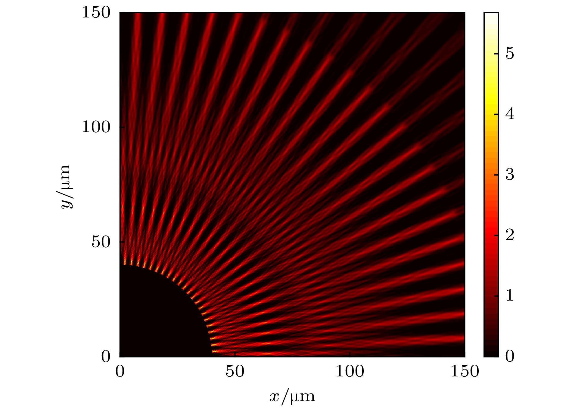 图 2 Lumerical模拟结果(光栅内的光场已去除)


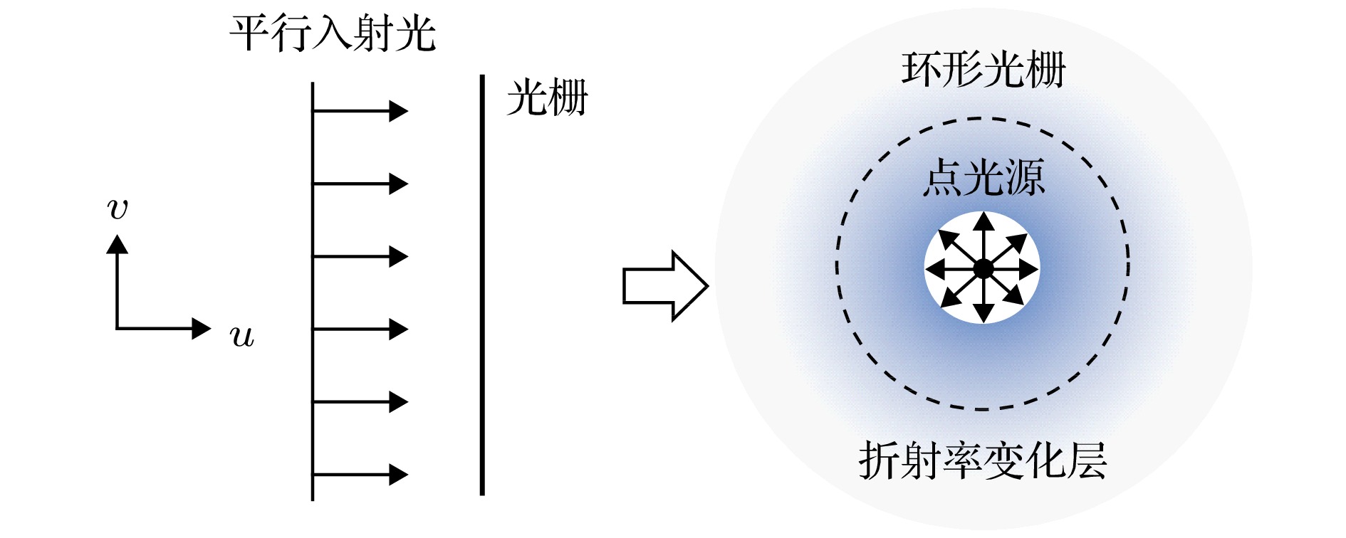 图 3 虚拟空间(左)和物理空间(右)示意图


 图 4 对于内径为10 μm, 外径为10.1 μm, m = 50,

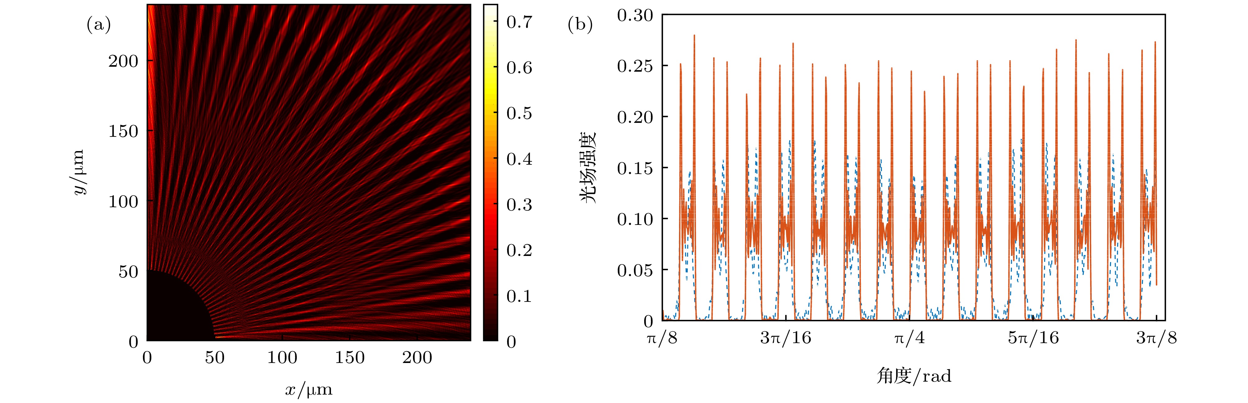 图 5 对于内径为50 μm, 外径为50.1 μm, m=120,

