引 言
人类日益增长的能源需求不仅导致了不可再生能源如煤炭、石油、天然气临近枯竭, 还加剧了全球环境的恶化. 为了解决这一问题, 人类开始寻找绿色可再生替代能源[1-2]. 全球海洋能最具有潜力, 能源提取的选择范围最广, 其中包括波浪、潮汐和洋流、海洋热能、盐度梯度、海洋生物能和海底地热能等[3-4]. 振荡水柱(oscillating water column, OWC)波能转换装置, 凭借其简单的结构[5]和较高的捕能宽度比被视为最具前途的技术之一[6-7]. 通常情况下, 振荡水柱由两部分构成, 一部分是浸没在水下底部开孔的空心结构, 另一部分是安装在空心结构上端的透平系统用来转换能量, 也被称为动力输出系统(PTO)[8-9]. OWC装置的墙体厚度、吃水深度、气室数量及宽度等参数极大影响着装置的转换性能, 许多****采用理论分析、数值模拟或物理试验的方法对这些参数的影响机制进行了广泛地研究. 如Rezanejad等[10]采用匹配特征函数展开法和边界积分方程法, 研究分析了台阶式海底地形的存在对OWC装置能量转换效率的影响, 发现在OWC装置下方布置尺寸合理的台阶地形, 能有效提升装置性能. Deng等[11]利用特征函数展开法对带有V型通道的OWC装置进行了理论分析, 结果发现V型通道能够显著提升OWC装置的波能转换效率并提出在实际海况中V型通道的最佳开口角度范围为


为进一步提升OWC装置的捕获效率, 一种具有两个气室的OWC装置的概念被提出. Rezanejad等[16]采用匹配特征函数展开法在线性波理论的基础上对置于台阶型底面上的固定式双气室OWC装置进行了理论分析, 发现阶梯型的地面能够在较宽的频域范围内显著提升双气室OWC装置的性能. He等[17]试验探究了不同的墙体吃水、水深变化、气室宽度对一种两端带有气室的浮动式箱式防波堤水动力性能的影响, 发现较小的前墙吃水能显著提高前气室的波能转换效率, 且装置前气室在波浪能转换方面发挥着主要的作用, 后气室仅仅是一个补充. 同时发现水深变化对装置的波能转换效率有着较小的影响. Ning等[18-20]基于势流理论和时域高阶边界元法对一种固定在岸堤上, 共用一个空气透平的双振荡水柱OWC装置进行了数值模拟研究, 发现波长与气室内水面高度的正相关性, 并通过物理试验探究了固定式的传统双气室OWC装置的水动力特性, 发现波能转换效率随前墙吃水深度的增加而降低. Wang等[21]提出一种由一个岸式固定气室和一个可垂荡运动的离岸气室组成的新型双气室OWC装置, 并利用开源软件OpenFOAM和VOF方法对该装置的水动力特性进行了数值模拟研究, 发现较小的前后气室宽度比和较浅的前OWC装置的后墙吃水更有助于系统在更宽波频带进行高效运行. Elhanafia等[22]对双气室OWC装置的几何构型和PT0阻尼等参数对装置转换效率的影响进行了系统的数值研究, 提出了一组满足双气室OWC装置最优性能下的最佳设计参数. 但该研究没有考虑双气室OWC装置在更宽波浪频率范围内的水动力性能, 也没有考虑该装置在垂荡响应情况下的效率优化机制.
在实际应用中, 为获得更多的波浪能量, OWC装置更倾向于往离岸区域布置运行[23]. 在水深较浅的离岸区域, OWC装置多采用桩基结构进行支撑, 由于技术和成本的制约, OWC装置不可能完全固定在水面上, 上下垂荡运动在所难免[24], 因此很有必要探究双气室OWC装置在垂荡响应情况下的水动力特性和效率优化机制. 当前研究聚焦于这一点, 基于开源流体动力学代码平台OpenFOAM, 借助waves2Foam工具箱进行造/消波, 采用动网格技术数值模拟研究了不同入射波下, 前后气室宽度比和锚固弹簧的弹性系数对垂荡式双气室OWC装置系统的水动力性能的影响规律, 以期为实际工程中垂荡式双气室OWC波能装置的设计提供参考依据.
1.
数学模型
1.1
控制方程
借助基于OpenFOAM中interFoam求解器开发的waves2Foam工具箱, 通过有限体积法离散求解雷诺平均纳维?斯托克斯方程(RANS)来数值模拟研究波浪OWC装置相互作用的水动力学问题. 在二维不可压缩黏性流体的假设下, 流体流动需满足质量守恒方程和动量守恒方程
$$nabla cdot {boldsymbol{U}}{text{ = }}0$$  | (1) |
$$ begin{split}& frac{{partial ho {boldsymbol{U}}}}{{partial t}} + nabla cdot ( ho {boldsymbol{UU}}) - nabla cdot left( {{mu _{{text{eff}}}}nabla {boldsymbol{U}}} ight) = &qquad - nabla {p^ * } - {boldsymbol{gX}} cdot nabla ho + nabla {boldsymbol{U}} cdot nabla {mu _{{ m{eff}}}} + sigma kappa nabla alpha end{split} $$  | (2) |
$$ {mu _{{ m{eff}}}} = mu + ho {v_{{ m{turb}}}} $$  | (3) |
其中

ho $


m{eff}}}}$


论文通过定义每个离散单元内空气和水的体积分数, 利用VOF (volume of fluid)法[25]捕捉空气?水的交界面, 体积分数满足对流方程即
$$ frac{{partial {varPhi }}}{{partial {text{t}}}} + nabla cdot left( {{boldsymbol{U}}{varPhi }} ight) = 0 $$  | (4) |
其中


ight]$

$$ frac{{partial {varPhi }}}{{partial t}} + nabla cdot left( {{boldsymbol{U}}{varPhi }} ight) + nabla cdot {U_{ m{r}}}{varPhi }left( {1 - {varPhi }} ight) = 0 $$  | (5) |
式中
m{r}}}$


因此, 整个计算域内流体的混合密度
ho $


$$ ho = {varPhi }{ ho _{ m{w}}} + left( {1 - {varPhi }} ight){ ho _{ m{a}}} $$  | (6) |
$$ mu = {varPhi }{mu _{ m{w}}} + left( {1 - {varPhi }} ight){mu _{ m{a}}} $$  | (7) |
其中
ho _{
m{w}}}$

ho _{
m{a}}}$

m{w}}}$

m{a}}}$

1.2
数值算法
OpenFOAM基于二阶精度有限体积法的框架发展了一系列插值格式对单元体中心点上的物理量进行空间时间积分求解[29]. 本研究中Navier?Stokes方程的时间项求解采用隐式欧拉格式, 对流项求解采用Gauss Limited Linear 1格式, 黏性扩散项求解采用线性修正格式, 其余项采用线性插值. 为了更精确捕捉自由面, 对新引进的界面压缩项采用Gauss Interface Compression格式, 体积分数方程中的对流项采用Gauss MUSCL求解. 速度压力场采用PIMPLE算法求解. PIMPLE算法是非迭代的瞬态PISO (pressure implicit with splitting of operator)算法和迭代的稳态SIMPLE (semi-implicit method for pressure linked equation)算法的结合, 核心思想是将每个时间步内看成稳态流动, 用SIMPLE稳态算法求解, 用PISO算法进行时间步进.
1.3
造波与消波
Waves2Foam通过在一定计算区域内设置理论目标波浪速度和自由高程的方法进行造波, 通过在数值波浪水槽两端设置松弛域, 可同时实现造波与消波功能[30]. 松弛函数的表达式如下
$${alpha _{{ m{re}}}}left( {{chi _{{ m{re}}}}} ight) = 1 - frac{{exp left( {chi _{{ m{re}}}^{3.5}} ight) - 1}}{{{text{e}} - 1}},;; {chi _{{ m{re}}}} in [0,1]$$  | (8) |
$$ {{boldsymbol{U}}_{ m{o}}} = {alpha _{{ m{re}}}}{{boldsymbol{U}}_{{ m{num}}}} + left( {1 - {alpha _{{ m{re}}}}} ight){{boldsymbol{U}}_{{ m{ana}}}} $$  | (9) |
式中,
m{o}}}$

m{re}}}}$

m{re}}}}$

m{num}}}}$

m{ana}}}}$


m{ana}}}}$
$$ {u}_{x}=frac{Homega mathrm{cos}text{h}left[kleft(z+h ight) ight]}{2mathrm{sinh}left(kh ight)}mathrm{cos}left(kx-omega t ight) $$  | (10) |
$$ {u}_{z}=frac{Homega mathrm{sin}text{h}left[kleft(z+h ight) ight]}{2mathrm{sinh}left(kh ight)}mathrm{sin}left(kx-omega t ight) $$  | (11) |
自由表面高程

$$ {eta _i}left( {x,t} ight) = frac{H}{2}cos left( {kx - omega t} ight) $$  | (12) |
式中,


2.
捕能宽度比计算
OWC装置捕能宽度比与装置气室内水柱振荡及气室内外压强差随时间的变化直接相关. 本文用顶部开孔模型来模拟PTO阻尼系统, 将顶部开孔的宽度与气室顶部宽度之比定义为开孔率, 开孔率选取

OWC装置在一个完整波浪周期T的作用下平均转换的波浪能为
$$ {E_{{ m{OWC}}}} = frac{1}{T}displaystylemathop int limits_t^{t + T} {P_a}left( t ight)qleft( t ight){ m{d}}t $$  | (13) |
对做垂荡运动的OWC装置有
$$begin{split} & {a}_{{ m{OWC}}}^{y}(t)= &left[underset{{S}_{{ m{p}}}}{{displaystyle iint }}P(t)text{d}S+{P}_{{ m{a}}}(t){S}_{{ m{a}}}-tilde{K}{eta }_{{ m{OWC}}}(t)-{m}_{{ m{OWC}}}g ight]Biggr/{m}_{{ m{OWC}}} end{split}$$  | (14) |
其中, OWC装置所受的力为
$$ F=underset{{S}_{{ m{p}}}}{{displaystyle iint }}P(t)text{d}S+{P}_{{ m{a}}}(t){S}_{{ m{a}}}-tilde{K}{eta }_{{ m{OWC}}}(t)-{m}_{{ m{OWC}}}g $$  | (15) |
式中,
m{OWC}}^y(t) $


ight)$

m{p}}}$

m{a}}}$

m{a}}}$


m{OWC}}}(t) $

m{OWC}}} $


水柱运动和OWC装置垂荡运动均处在同一惯性参考系中, 规定竖直向上的方向为正方向. 于是, 开孔处空气流率可表示为
$$ qleft(t ight)=Big[dot{eta }left(t ight)- {dot{eta }}_{{ m{OWC}}}left(t ight)Big]bw $$  | (16) |
因此, 式(13)可改写成
$$ {E}_{{ m{OWC}}}=dfrac{bw}{T}underset{t}{overset{t+T}{{displaystyle int }}}{P}_{{ m{a}}}left(t ight)Big[dot{eta }left(t ight)- {dot{eta }}_{{ m{OWC}}}left(t ight)Big]{ m{d}}t $$  | (17) |
式中,

ight) $

m{OWC}}}}left( t
ight)$


基于线性波理论, 单位宽度入射波含有的能流密度为
$$ {P_{{text{inc}}}} = frac{{{ ho _{ m{w}}}gA_{ m{i}}^2omega }}{{4k}}left[ {1 + frac{{2kh}}{{sinh (2kh)}}} ight] $$  | (18) |
式中,
m{i}}} $

因此OWC装置捕能宽度比

$$ xi = frac{{{E_{{ m{OWC}}}}}}{{{P_{{text{inc}}}} cdot w}} $$  | (19) |
垂荡式双气室OWC装置共有前后两个气室, 因此总的捕能宽度比为
$$ {xi _{{ m{total}}}} = {xi _{{ m{front}}}} + {xi _{{ m{rear}}}} $$  | (20) |
式中,
m{front}}}}$

m{rear}}}}$

m{total}}}}$

3.
模型验证
3.1
数值波浪水槽
本研究采用结构化网格对计算域进行离散. 计算域的长度等于10倍波长, 左右两端各设置2倍波长的松弛域区用来吸收反射波, 值得注意的是, 本研究根据不同周期的波浪调整计算域的长度使之保持10倍波长, 以保证在入射波与被结构物反射回来的波互相干扰前收集到稳定的6个周期的波浪数据. 该计算域的水深0.5 m, 空气部分高度为0.5 m, 在水气交界面上下2倍波高区域进行加密以防止波浪沿程衰减. 对于每个周期入射波, 始终保证计算域的长度为10倍波长, 因此大大节省了计算资源, 每套网格数量大约11万左右, 采用28核服务器分块并行运算, 每个工况计算用时约12小时.
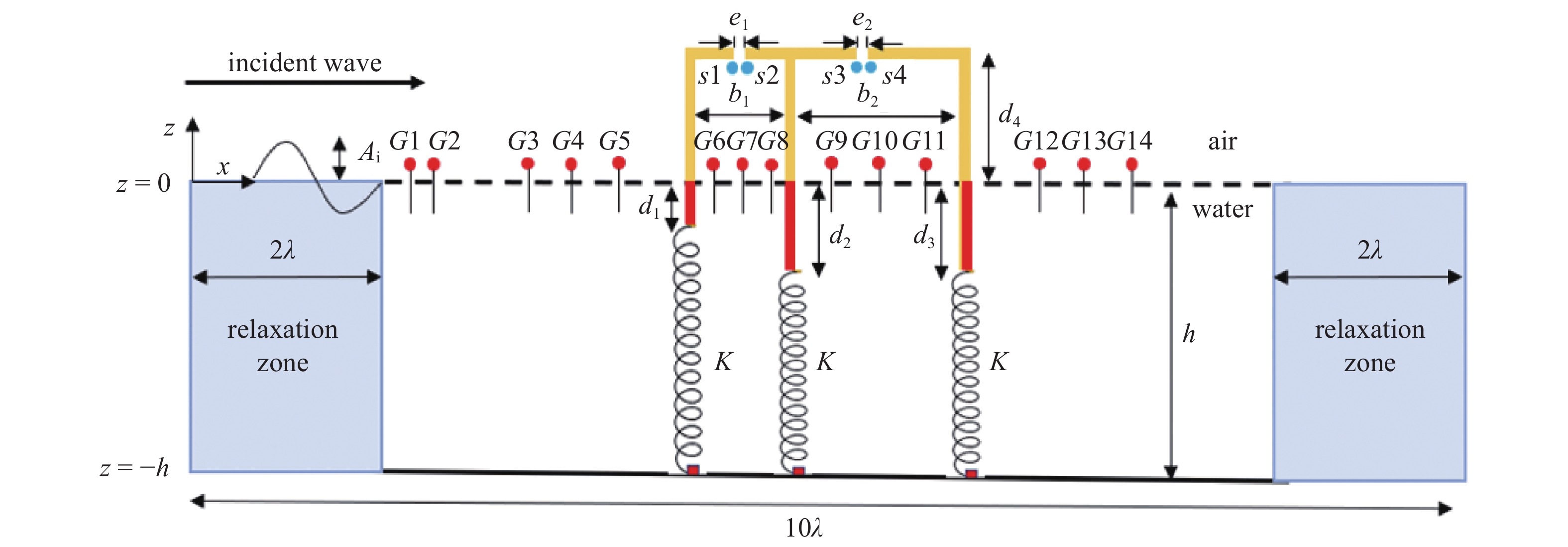
图1为本研究中垂荡式双气室OWC装置数值设置示意图, 结构物前墙吃水深
m{m}}$

m{m}}$

m{m}}$


m{i}}}$

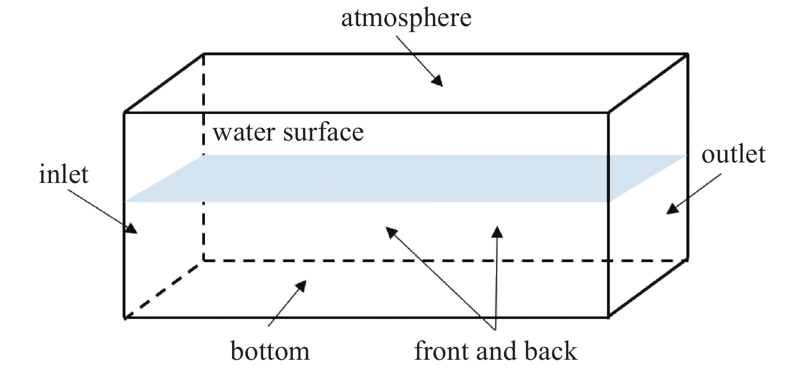
在OpenFOAM中, 数值波浪水槽共存在5个边界, 如图2所示, 最左侧为入口边界, 即造波边界, 最右侧为出口边界, 顶部为空气边界, 底部为床面边界, 前后两侧定义为侧壁边界. 对于二维问题, 因此侧壁边界为空边界. 边界条件是控制方程有确定解的前提, 对于任何问题, 都需要给定边界条件, 边界条件的处理直接影响计算结果的精度. 表2为本文数值模型选择的边界条件.
 onerror="this.onerror=null;this.src='https://lxxb.cstam.org.cn/fileLXXB/journal/article/lxxb/2021/9//lxxb2021-072-1.jpg'"
 class="figure_img
figure_type2 ccc " id="Figure1" />
图
1
垂荡式双气室OWC装置数值设置示意图
Figure
1.
Schematic diagram of an offshore heave-only dual-chamber OWC system
 下载:
下载: 全尺寸图片
幻灯片
表
1
本研究所使用的波浪参数
Table
1.
Wave parameters in this study
table_type1 ">
| ${{T} }_ { { m{s} } }$ | ${omega ^2}h/{ m{g}}$ | $h/ { m{m}} $ | $H/ { m{m}} $ | ${ m{lambda } }/ { m{m}} $ | $ H/lambda $ |
| 1 | 2.01215 | 0.5 | 0.04 | 1.5130 | 0.026438 |
| 1.1 | 1.66294 | 0.5 | 0.04 | 1.7813 | 0.022456 |
| 1.2 | 1.39733 | 0.5 | 0.04 | 2.0483 | 0.019528 |
| 1.3 | 1.19062 | 0.5 | 0.04 | 2.3118 | 0.017303 |
| 1.4 | 1.02661 | 0.5 | 0.04 | 2.5712 | 0.01557 |
| 1.5 | 0.89429 | 0.5 | 0.04 | 2.8265 | 0.014152 |
| 1.6 | 0.78600 | 0.5 | 0.04 | 3.0781 | 0.012995 |
| 1.7 | 0.69625 | 0.5 | 0.04 | 3.3266 | 0.012024 |
| 1.8 | 0.62103 | 0.5 | 0.04 | 3.5722 | 0.011198 |
| 1.9 | 0.55738 | 0.5 | 0.04 | 3.8153 | 0.010484 |
下载: 导出CSV
|显示表格
 onerror="this.onerror=null;this.src='https://lxxb.cstam.org.cn/fileLXXB/journal/article/lxxb/2021/9//lxxb2021-072-2.jpg'"
 class="figure_img
figure_type1 bbb " id="Figure2" />
图
2
数值波浪水槽边界示意图
Figure
2.
Setup of the numerical wave tank
下载: 全尺寸图片
幻灯片
表
2
数值波浪水槽边界条件设置
Table
2.
Boundary conditions of numerical wave tank
table_type1 ">
| Boundary | Velocity field | Pressure field | Volume phase field |
| inlet | wave velocity | zero gradient | wave alpha |
| bottom | fixed value (0,0,0) | zero gradient | zero gradient |
| atmosphere | pressure inlet outlet velocity | total pressure | inlet outlet |
| outlet | fixed value (0,0,0) | zero gradient | zero gradient |
| front and back | empty | empty | empty |
下载: 导出CSV
|显示表格
3.2
网格收敛性验证
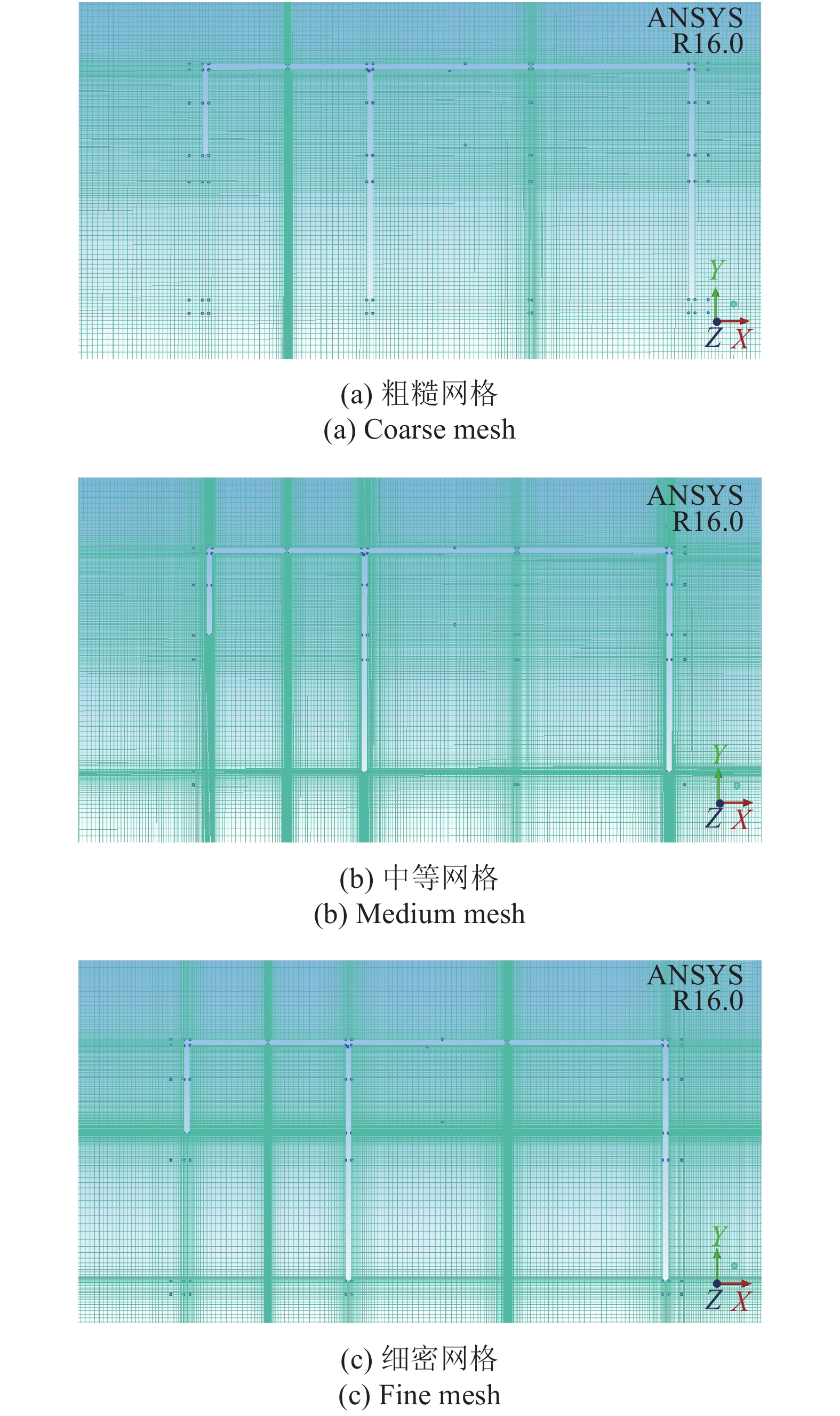
对于波浪与结构物相互作用而言, 结构物附近的网格分辨率对其水动力性能的数值计算结果有着很大影响, 特别是在结构物尖角附近[31-32]. 为了精确的捕捉流体在结构物尖角处的流场信息并在求解的精度及计算时间上取得平衡, 本研究对结构物附近的网格进行收敛性分析以求得最佳的网格划分策略.
本研究采用Elhanafia等[22]提到的结构与工况进行网格收敛性验证. 在水深

 onerror="this.onerror=null;this.src='https://lxxb.cstam.org.cn/fileLXXB/journal/article/lxxb/2021/9//lxxb2021-072-3.jpg'"
 class="figure_img
figure_type1 bbb " id="Figure3" />
图
3
结构物周围不同粗细网格
Figure
3.
Different spatial resolutions around the dual-chamber OWC system
下载: 全尺寸图片
幻灯片
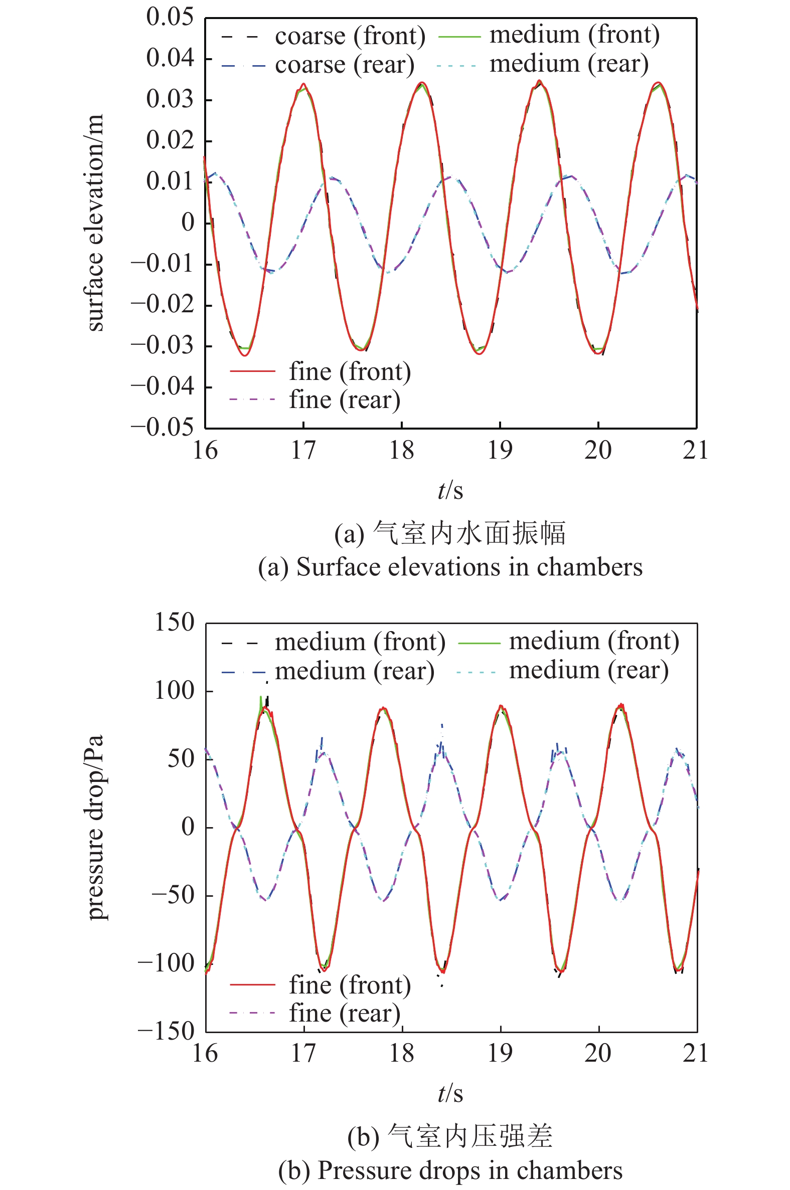
图4为不同分辨率网格的气室内水面振幅与压强差历时曲线. 由图4可知, 对于压强和波面监测数据, 除了波峰和波谷外, 3组网格的差异不大, 说明了双气室OWC装置周围计算区域的网格收敛, 表3为以细密网格条件下的数值结果作为计算依据的粗糙、中等网格分辨率对应的前后气室内压强与水面振幅的标准均方根误差, 结果表明, 对于中等网格, 检测结果最大误差小于1%, 满足精度要求. 此后采用中等网格分辨率即加密区网格大小为0.002 m作为网格划分方案进行计算.
 onerror="this.onerror=null;this.src='https://lxxb.cstam.org.cn/fileLXXB/journal/article/lxxb/2021/9//lxxb2021-072-4.jpg'"
 class="figure_img
figure_type1 bbb " id="Figure4" />
图
4
不同分辨率网格的气室内水面振幅与压强差历时曲线
Figure
4.
Convergence tests of surface elevations and pressure drops in the chambers for grids with different resolutions
下载: 全尺寸图片
幻灯片
表
3
不同分辨率网格条件下气室内波面和压强差标准均方根误差
Table
3.
NRMSE of surface elevations and pressure drop under different spatial resolutions around the dual-chamber OWC system
table_type1 ">
| Grid resolution | NRMSE/% | |||
| front chamber | rear chamber | |||
| water surface | pressure drop | water surface | pressure drop | |
| coarse | 0.735 | 5.443 | 0.371 | 6.417 |
| medium | 0.279 | 0.537 | 0.131 | 0.763 |
| fine | ? | ? | ? | ? |
下载: 导出CSV
|显示表格
3.3
求解器WaveDyMFoam的验证
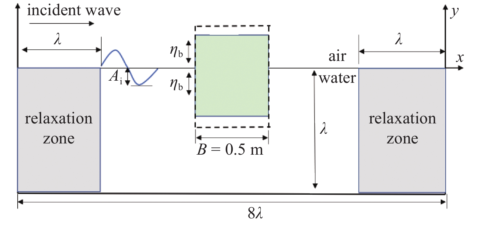
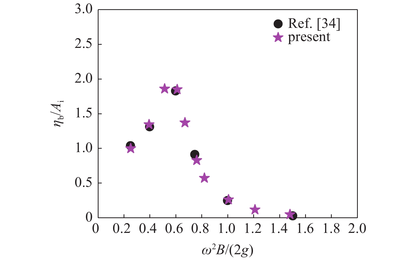
本研究采用耦合了六自由度(6DOF)运动方程和动网格技术的WaveDyMFoam求解器对波浪与结构物相互作用造成的结构物升沉运动进行数值计算, 为了确保计算结果的真实性和有效性, 有必要与Luo等[34]的研究数据进行对比验证. 图5为模型示意图, 其中,

m{i}}}$

m{b}}}$


m{b}}}/{A_{
m{i}}}$


 onerror="this.onerror=null;this.src='https://lxxb.cstam.org.cn/fileLXXB/journal/article/lxxb/2021/9//lxxb2021-072-5.jpg'"
 class="figure_img
figure_type1 bbb " id="Figure5" />
图
5
波浪与浮动式结构物相互作用示意图[34]
Figure
5.
Sketch diagram of heave-only box[34]
下载: 全尺寸图片
幻灯片
 onerror="this.onerror=null;this.src='https://lxxb.cstam.org.cn/fileLXXB/journal/article/lxxb/2021/9//lxxb2021-072-6.jpg'"
 class="figure_img
figure_type1 bbb " id="Figure6" />
图
6
结构物相对振幅
m{b}}}/{A_{
m{i}}}$

Figure
6.
Relative heave amplitude
m{b}}}/{A_{
m{i}}}$
 下载:
下载: 全尺寸图片
幻灯片
3.4
捕能宽度比计算方法验证
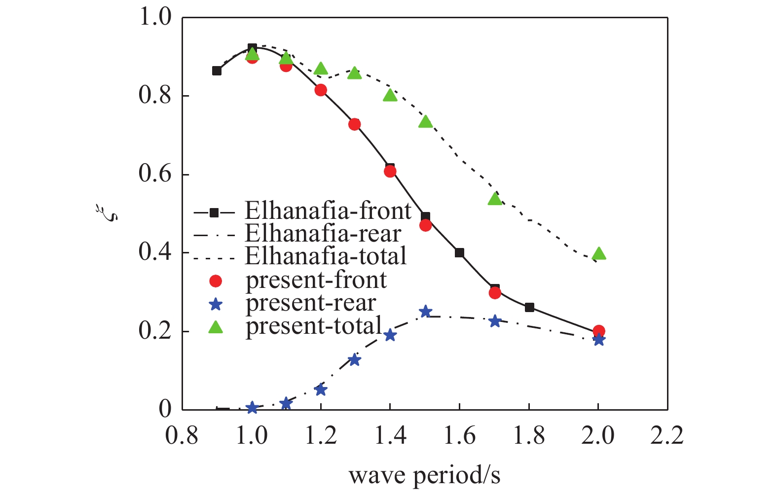
本研究的重点是预测垂荡式双气室OWC装置的捕能宽度比, 因此将捕能宽度比的计算结果与以往的结果作对比验证显得至关重要.
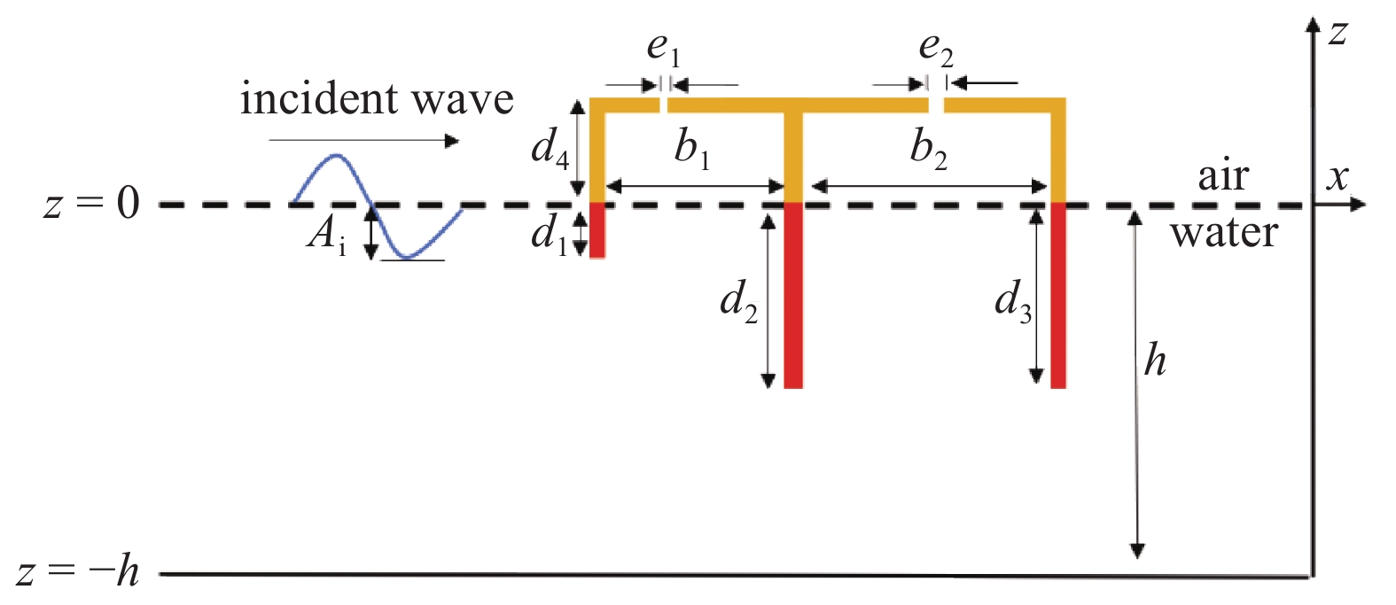
与Elhanafia等[22]研究的固定式双气室OWC装置数值模型进行对比验证(见图7). 基本参数如下: 水深


m{i}}$

 onerror="this.onerror=null;this.src='https://lxxb.cstam.org.cn/fileLXXB/journal/article/lxxb/2021/9//lxxb2021-072-7.jpg'"
 class="figure_img
figure_type1 bbb " id="Figure7" />
图
7
Elhanafia等[22]研究的双振荡水柱OWC装置示意图
Figure
7.
Schematic diagram of the dual-chamber device proposed by Elhanafia et al.[22]
下载: 全尺寸图片
幻灯片
 onerror="this.onerror=null;this.src='https://lxxb.cstam.org.cn/fileLXXB/journal/article/lxxb/2021/9//lxxb2021-072-8.jpg'"
 class="figure_img
figure_type1 bbb " id="Figure8" />
图
8
当前研究与Elhanafia等[22]捕能宽度比对比
Figure
8.
Comparison of energy capture width ratio
m{xi }}$
 下载:
下载: 全尺寸图片
幻灯片
4.
结果讨论
OWC装置的工作原理是利用进入气室内的波浪使气室内水柱发生振荡进而压缩气室内的气体使其做功. 气室内气体所获得的能量是通过气室内水柱升沉运动转换而来的. 这里采用气室内的水面振幅表征气体做功量, 故定义气室内水面振幅

m{i}}}$

m{i}}}$

值得一提的是, 在实际工程中, 垂荡式双气室OWC装置采用桩支承结构体系, 只允许装置在竖直方向往复运动, 底部设置锚固系统能够降低竖直运动响应对系统的不利影响, 提高系统作业稳定性. 在数值模拟中, 在模型底部设置线性弹簧来模拟锚固系统并对弹性系数进行无量纲化处理, 即
$$ K = frac{{tilde K}}{{ ho g{s_{ m{d}}}}} $$  | (21) |
式中,
m{d}}$

4.1
相对气室宽度对捕能宽度比的影响
OWC装置的气室宽度对装置的性能提升有很大影响. 因此垂荡式双气室OWC装置的前后气室宽度比对装置的水动力特性的影响被首先考虑. 保持总的气室宽度不变(
m{m}}$


m{m}}$

m{OWC}}}}/{A_{
m{i}}}$

m{OWC}}}}$

表
4
不同气室宽度参数设置
Table
4.
Cases for different front (


table_type2 ">
| Geometric parameters ($ {e_1}{text{ = }}{e_1}{text{ = }}1% $) | |||||||
| $ {d_1}/{ m{m}} $ | ${d_2}/{ m{m}}$ | ${d_3}/{ m{m}}$ | $h/{ m{m}}$ | ${b_1}$ | ${b_2}$ | ${b_1}/{b_2}$ | $ {b_1}/h $ |
| 0.06 | 0.25 | 0.25 | 0.5 | 0.05 | 0.25 | 0.2 | 0.1 |
| 0.06 | 0.25 | 0.25 | 0.5 | 0.1 | 0.2 | 0.5 | 0.2 |
| 0.06 | 0.25 | 0.25 | 0.5 | 0.15 | 0.15 | 1 | 0.3 |
| 0.06 | 0.25 | 0.25 | 0.5 | 0.2 | 0.1 | 2 | 0.4 |
| 0.06 | 0.25 | 0.25 | 0.5 | 0.25 | 0.05 | 5 | 0.5 |
下载: 导出CSV
|显示表格
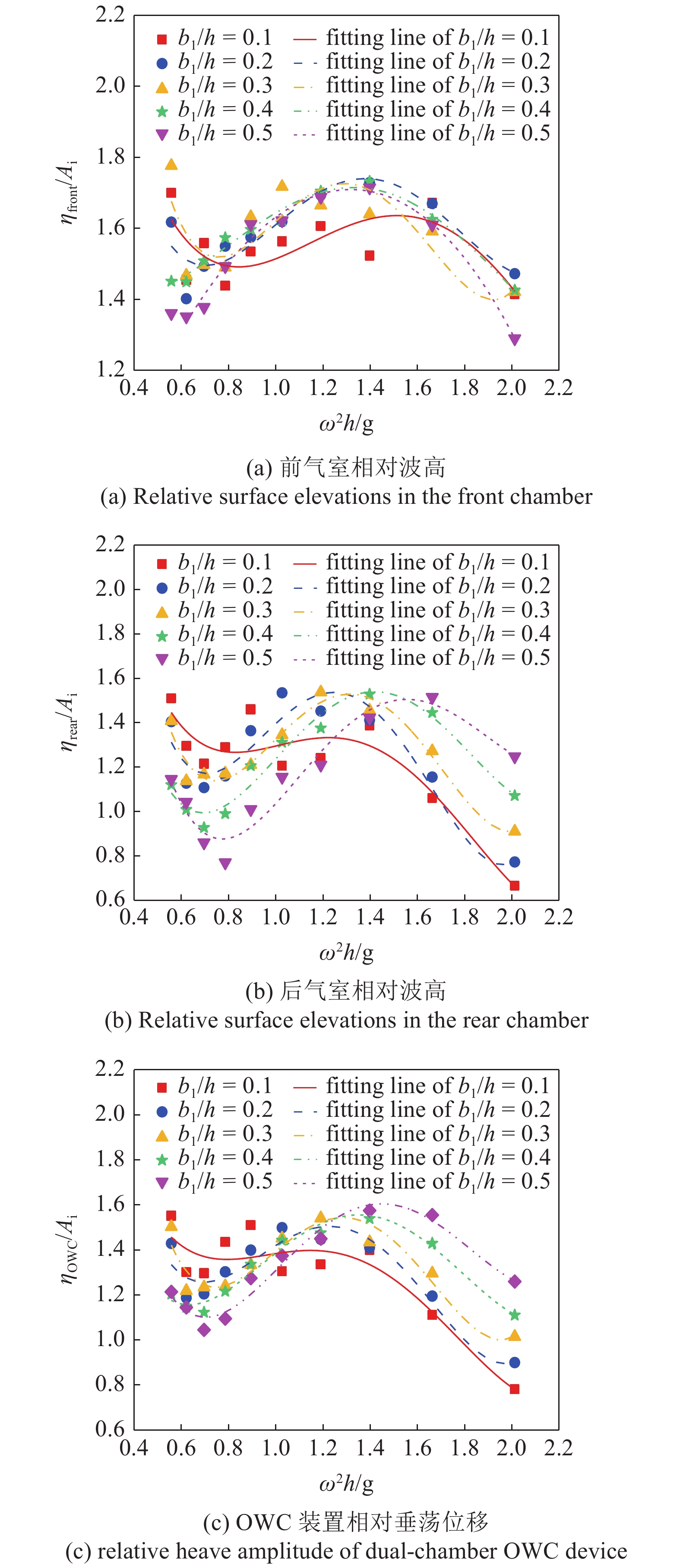
图9揭示了相对气室宽度对OWC装置气室内相对波高与OWC装置相对位移的影响规律. 在给定波浪频率下, 各曲线有着相似的变化趋势. 随着波频的增加前气室内相对波高先减小再增大随后继续减小, 在中波频段出现较大值. 这是因为高频波作用下OWC装置相对位移较小(见图9(c)), 短波被大量反射. 后气室内相对波高在测试波频段内与前气室有着相似的规律(见图9(b)), OWC装置相对垂荡位移随波浪频率的变化也呈现先减小在增大随后继续减小的规律(见图9(c)). 同时发现, 不同的相对气室宽度在中波频段对前期室内相对波高影响不大, 但在低波频和高波频段影响较大. 以上分析说明一个合理的较小的前气室宽度有助于垂荡式双气室OWC装置对短波能量的提取.
 onerror="this.onerror=null;this.src='https://lxxb.cstam.org.cn/fileLXXB/journal/article/lxxb/2021/9//lxxb2021-072-9.jpg'"
 class="figure_img
figure_type1 bbb " id="Figure9" />
图
9
相对气室宽度对OWC装置气室内相对波高与OWC装置相对垂荡幅度的影响
Figure
9.
Relative surface elevations of the front and rear chamber and the relative dual-chamber OWC device heave amplitude against different relative chamber length
 下载:
下载: 全尺寸图片
幻灯片
由图9(b)可知, 相对气室宽度对后气室内相对波高的影响较为明显, 随着相对气室宽度的增加, 后气室内相对波高最大值开始由中波频段向高波频段移动, 且在高波频段气室内水柱运动的越来越剧烈. 这说明, 较宽的后气室有利于垂荡式双气室OWC装置对中、长波能量的提取.
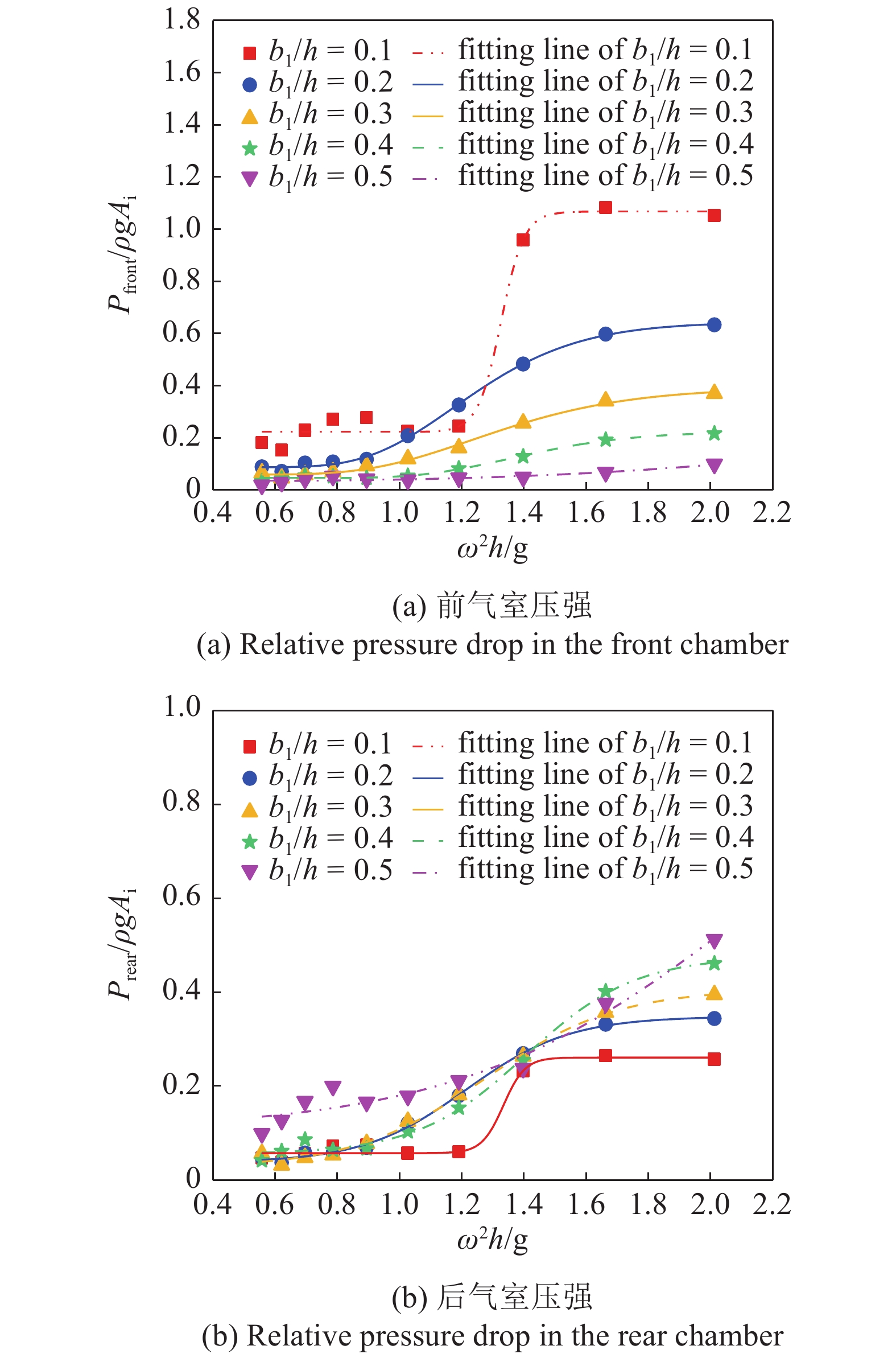
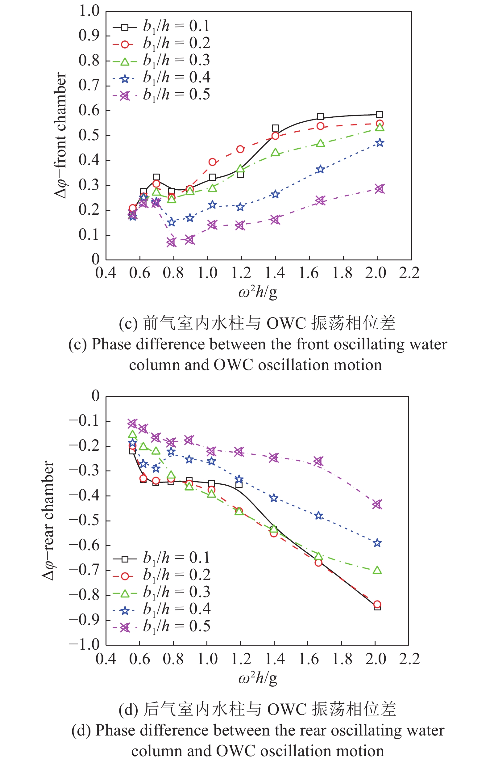
图10为相对气室宽度对垂荡式双气室OWC装置气室相对压强、气室内水面振荡运动与OWC垂荡运动相位差的影响规律. 由图10(a)和图10(c)可知, 对于确定的相对气室宽度, 在中、高波频段气室内相对压强随入射波频的变化与相位差的绝对值随入射波频的变化较一致, 都是随着波频的增加而增加, 且相位差的绝对值越大, 气室内相应的相对压强越大, 在高波频段(

 onerror="this.onerror=null;this.src='https://lxxb.cstam.org.cn/fileLXXB/journal/article/lxxb/2021/9//lxxb2021-072-10-1.jpg'"
 class="figure_img
figure_type1 bbb " id="Figure10-1" />
10
相对气室宽度对垂荡式双气室OWC装置前后气室相对压强、前后气室内水面振荡与OWC自身垂荡相位差的影响
10.
Relative pressure drops and the phase difference between the oscillating water column in the chambers and OWC oscillation motion as a function of the dimensionless frequency

 下载:
下载: 全尺寸图片
幻灯片
 onerror="this.onerror=null;this.src='https://lxxb.cstam.org.cn/fileLXXB/journal/article/lxxb/2021/9//lxxb2021-072-10.jpg'"
 class="figure_img
figure_type1 bbb " id="Figure10" />
图
10
相对气室宽度对垂荡式双气室OWC装置前后气室相对压强、前后气室内水面振荡与OWC自身垂荡相位差的影响 (续)
Figure
10.
Relative pressure drops and the phase difference between the oscillating water column in the chambers and OWC oscillation motion as a function of the dimensionless frequency

 下载:
下载: 全尺寸图片
幻灯片
在低波频段(

总的来说, 对于垂荡式双气室OWC装置而言, 保持气室总宽度的不变, 增大前气室的宽度, 会降低前气室内相对压强, 提高后气室内的相对压强, 前后气室存在相互制约的关系. 这种制约是通过改变装置垂荡运动与气室内水柱振荡运动的相位差实现的.
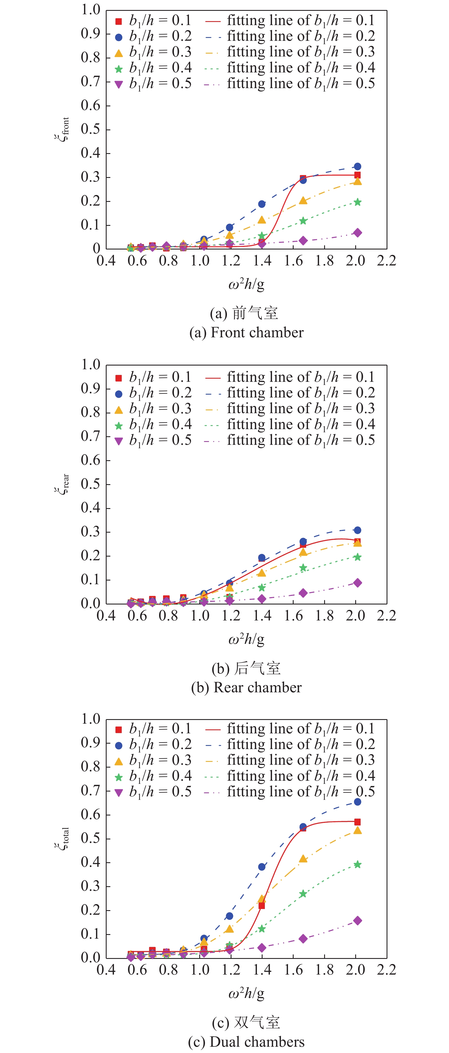
图11揭示了相对气室宽度对垂荡式双气室OWC装置气室捕能宽度比的影响规律. 由图11(a)可知, 相对气室宽度对前气室的波能提取效率在中、高波频段(


 onerror="this.onerror=null;this.src='https://lxxb.cstam.org.cn/fileLXXB/journal/article/lxxb/2021/9//lxxb2021-072-11.jpg'"
 class="figure_img
figure_type1 bbb " id="Figure11" />
图
11
相对气室宽度对垂荡式双气室OWC装置气室捕能宽度比的影响
Figure
11.
Capture width ratio of the heave-only dual OWCs for relative chamber lengths
 下载:
下载: 全尺寸图片
幻灯片
4.2
无量纲弹性系数对转换效率的影响
本研究考虑了K = 0, 1, 2, 4和8这5个无量纲弹簧弹性系数, 通过与K =

图12为无量纲弹簧弹性系数K对垂荡式双气室OWC装置各气室捕能宽度比的影响. 由图12(a)可知, 对于前气室, 装置固定时(


 onerror="this.onerror=null;this.src='https://lxxb.cstam.org.cn/fileLXXB/journal/article/lxxb/2021/9//lxxb2021-072-12.jpg'"
 class="figure_img
figure_type1 bbb " id="Figure12" />
图
12
无量纲弹簧弹性系数K对垂荡式双气室OWC装置各气室捕能宽度比的影响
Figure
12.
Capture width ratio of the heave-only dual OWCs for different K
下载: 全尺寸图片
幻灯片
5.
结论
(1)相对气室宽度对垂荡式双气室OWC装置的前后气室以及总的捕能宽度比有着较大的影响, 合理的布置前后气室宽度比有利于装置捕能宽度比的提升. 后气室比前气室宽的结构布置使得垂荡式双气室OWC装置有着更宽的高效频率带和最大的捕能宽度比. 在本研究中, 最佳的前后气室宽度比1∶2.
(2)通过改变OWC装置的垂荡幅度和气室内水柱振荡运动与OWC装置垂荡运动的相位差, 弹簧的弹性系数可显著影响垂荡式双振荡水柱OWC装置的捕能宽度比. 较大的弹性系数能够显著拓宽垂荡式OWC装置的高效频率带和提高在低、中波频段的捕能宽度比, 但会少量降低装置在高波频段的波能捕获性能. 本研究中当


m{total}}}}{text{ = }}68%$

(3)垂荡式双气室OWC装置的后气室与前气室在波能转换上承担着同样重要的作用. 当弹性系数

致谢: 本研究得到浙江大学舟山校区高性能计算中心的支持.
