全文HTML
--> --> -->超透镜是基于超表面的平面透镜, 具有超薄、平面化和小型化的优点, 因此近年来受到了国内外研究者的广泛关注. 根据不同的场合应用需求, 人们提出并制作了不同类型的超透镜, 例如高效率的全介质超透镜[12,13]、无色散超透镜[14-16]、消慧差超透镜[17]、横向多焦点超透镜[18]以及大数值孔径超透镜[19]等.
分辨率、数值孔径、焦点深度(焦深)是描述超透镜聚焦能力的参数[20]. 为了尽可能获取清晰的目标成像, 超透镜必须具有较高的分辨率, 但另一方面, 某些需要宽广成像范围的应用场合要求超透镜具有较大的焦深. 尽管增大焦深的同时必然要以牺牲分辨率为代价, 但大焦深透镜能获得更多的物方信息量, 可以校正由球差、色差引起的误差, 以及由安装误差和温度变化造成的离焦而引起的误差, 也可以更好地进行三维显示, 产生更加真实、适合于人眼的三维视觉. 因此, 大焦深的透镜在生物观测、医学三维成像、虹膜识别、光刻与光存储等领域都具有广泛的应用前景[21].
目前, 绝大多数超透镜都是共轴聚焦的, 即焦点位于超透镜的光轴(超透镜的对称轴)上, 而离轴超透镜可将入射波聚焦到偏离光轴的任意方向上, 因此在小型化、平面化的离轴光学系统中具有潜在的应用价值. 2016年, 哈佛大学的课题组[22]基于离轴超透镜制备了近红外波段的紧凑型高分辨率光谱仪, 并通过优化入射孔径、离轴偏转角等参数来提高光谱仪的分辨率; 2017年, Capasso课题组[23]利用同样的设计思路制备了一款可见光波段的光谱仪. 同年, 浙江大学马云贵课题组[24]基于离轴超透镜设计了波分解复用器件. 2019年 Capasso课题组[25]又提出了一种基于离轴超透镜的像差校正光谱仪, 在保持高分辨率的前提下增大了带宽和聚焦光斑质量, 而且聚焦点是沿着平面分布的, 更易于与探测器集成使用.
本文设计并制备了一种具有大焦深的离轴超透镜, 它仅由单层超表面构成, 结构简单. 从功能上看, 离轴聚焦可以看成是波束偏转与聚焦两种功能的叠加, 而相位叠加方法作为一种常用的功能融合的设计方法, 在多功能超表面的设计上具有直观、简洁的优势, 所以本文采用相位叠加的方法, 即将超表面实现波束偏转功能所需要的相位分布和实现聚焦功能所需要的相位分布进行简单的叠加, 由此来进行天线单元的参数选取和离轴聚焦透镜的设计. 此外, 在设计中还选取了合适的入射孔径和离轴偏转角来增大聚焦透镜的焦深. 这种大焦深的离轴超透镜在小型化、平面化的离轴光学系统以及大焦深成像系统中具有潜在的应用前景.
i) 为了实现透射波束的偏转功能(如图1(a)所示), 超表面需要为透射波提供如下的相位分布:
 图 1 (a)基于超表面的波束偏转器; (b)常规的共轴超透镜; (c)离轴超透镜
Figure1. (a) Beam deflector based on metasurface; (b) conventional on-axis meta-lens; (c) off-axis meta-lens.
ii) 为了实现聚焦功能, 超表面需要为透射波提供抛物线的相位轮廓, 其空间相位分布如下:
为了得到离轴超透镜, 可以将(1)式和(2)式中的相位进行叠加, 即:
与逆向设计的优化算法(例如遗传算法、禁忌搜索算法、模拟退火算法等)相比, 相位分布叠加方法作为一种常用的功能融合的设计方法, 具有更直观、清晰的物理意义. 为了实现相应的功能, 只需要将不同功能所要求的相位分布函数直接相加即可, 因此它在多功能超表面的设计上具有直观、简洁的优势. 除了本文中实现的离轴聚焦功能以外, 这种方法还可以实现涡旋光束聚焦[26]、涡旋光复用解复用[27]、多方向贝塞尔光束[28]等更多功能.
在实现离轴聚焦的功能之外, 需要想办法增大焦深. 通常, 超透镜的焦深(DOF)可表示为[29]
从(4)式可以看出, 为了增大超透镜的焦深, 可以采取减小入射孔径或增大焦距的方法. 但是, 过大程度地减小入射孔径会降低超透镜分辨率, 过大程度地增大焦距会增大整个光学系统的尺寸. 此外, 对于离轴超透镜, 焦深也与离轴偏转角α的取值有关, 减小离轴偏转角(α ≠ 0)可以增大焦深[30]. 但离轴偏转角也不能太小, 否则会失去离轴的效果.
因此, 为了增大超透镜的焦深, 同时又要保证一定的分辨率和离轴效果, 需要在仿真过程中不断地优化并选取合适的入射孔径、焦距以及离轴偏转角.
 图 2 (a)离轴超透镜的天线单元; (b)当频率为9 GHz的x偏振波垂直入射到天线单元时, 正交偏振波的透射率和透射相位随lx的变化关系; (c)满足(3)式的相位分布
Figure2. (a) Antenna unit of the off-axis meta-lens; (b) when an x-polarized wave with frequency of 9 GHz is incident perpendicularly onto the antenna units, transmittance and transmission phase of the orthogonal polarized wave vary with lx; (c) phase distributions satisfying Eq. (3).
为了构建出这种离轴超透镜, 首先, 需要寻找L型天线的臂长lx与透射相位之间的依赖关系. 采用三维时域有限差分(FDTD)方法进行数值仿真. 图2(b)给出了当频率为9 GHz的x偏振波垂直照射到超表面天线单元时, 其正交偏振波的透射率和透射相位随臂长lx的变化关系. 当lx从5.5 mm逐渐增加到10.5 mm时, 正交偏振波的透射率在0.13以上, 透射相位可以覆盖0°—180°. 对于等离子超表面, 将天线单元旋转90°后, 正交偏振分量可以获得额外的180°相位变化[23]. 即, 利用上述原则的操作, 入射正交偏振波的相位可以实现0°—360°范围的变化, 由此就可以设计出合适的天线单元来组成超表面以对透射波的正交偏振分量进行随意操控.
在工作频率f0 = 9 GHz处, 将焦距设置为F0 = 350 mm. 同时, 为了得到较大的焦深, 将透射波束的偏转角度设置为α = 30°、超透镜的入射孔径设置为D = 400 mm. 然后, 基于(3)式计算出相位分布(如图2(c)所示), 并利用图2(b)来选取天线的臂长取值, 依据(3)式的相位分布将这些天线进行排布, 便可构建出所需要的离轴超透镜.
图3(a)为实际制备的超表面样品的照片(矩形红色虚线为局部放大图), 样品总尺寸为400 mm × 400 mm. 图3(b)为实验测试装置. 在微波暗室中, 由发射天线发射出的x极化的电磁波信号垂直照射至测试样品, 然后透射的y极化电磁波信号被接收天线接收. 透射电磁波的电场强度分布通过矢量网络分析仪进行测量并记录.
 图 3 (a)制备的超表面样品的正面结构照片, 矩形红色虚线为局部放大图; (b)实验装置
Figure3. (a) Image of the fabricated metasurface sample, and the rectangular red dotted line is a zoom view; (b) experimental set-up.
 图 4 测试得到的不同频率处正交偏振波的电场强度分布 (a) 8 GHz; (b) 9 GHz; (c) 10 GHz. 红色点划线代表聚焦平面所在的位置, 倾斜的白色虚线代表u1轴、u2轴和u3轴
Figure4. Measured electric field intensity distributions of the orthogonal polarized waves at different frequencies: (a) 8 GHz; (b) 9 GHz; (c) 10 GHz. The red dotted lines represent the position of the focal planes, and the white dashed lines represent the u1 axis, u2 axis and u3 axis.
透镜焦点处的半峰全宽(full-wave half-maximum, FWHM)可以描述透镜聚焦光斑的成像质量. 一般来说, FWHM越小意味着聚焦能量越集中. 图5(a)和图5(b)分别给出了在预设的工作频率9 GHz处, 透镜焦点平面处归一化电场强度分布的仿真结果和实验结果. 可以看出, 仿真结果中焦点处的半峰全宽FWHM = 40.2 mm, 而实验结果中焦点处的半峰全宽达到了FWHM = 48.2 mm, 因此实际光斑的成像质量要略差一些. 出现这样的误差的原因如下: 样品制作中的工艺误差使得样品实际参数与仿真中的参数不一致. 此外, 在实验测试过程中, x方向上的采样间距过大也导致了实验误差. 除此之外, 还计算了频率为8和10 GHz时透镜焦点处的半峰全宽, 分别为59.2和53.5 mm.
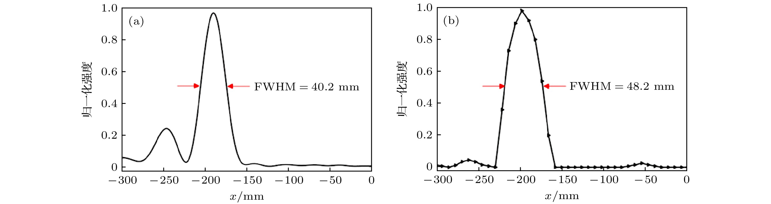 图 5 工作频率9 GHz处, 透镜焦点处归一化电场强度分布 (a)仿真结果; (b)实验结果
Figure5. At the working frequency of 9 GHz, the normalized electric field intensity distribution at the focal point of the metalens: (a) Simulation result; (b) experimental result.
另外还计算了超透镜的聚焦效率[31]:
应用(5)式, 计算得到该离轴超透镜在工作频率9 GHz处的聚焦效率为16.9%. 聚焦效率较低的主要原因是我们采用的是等离子体超表面, 只能对入射波的交叉偏振分量进行操控, 最高效率不会超过25%.
在上述的分析和讨论中, 验证了超透镜的离轴聚焦功能, 接下来还需要验证它的大焦深特性. 在焦深的测量过程中, 将焦深定义为聚焦光斑的最大强度减小为1/2时的轴向距离[21]. 由于离轴超透镜的聚焦光斑不在光轴上而且是倾斜的, 因此首先需要转换一下坐标轴. 根据图4(b)得到的测试结果分析可知, 两条白色虚线之间的夹角近似为所设计的离轴偏转角度, 因此建立新的坐标轴u = z/cosα, 如图4(a)—图4(c)中倾斜的白色虚线所示. 图6(a)—图6(c)分别给出了频率分别为8, 9和10 GHz时按照上述方法求出的焦深. 三个频率下的焦深分别为263.2, 278.5和298.2 mm, 分别对应波长的7.02倍、8.36倍和9.98倍. 这说明所设计的离轴超透镜在不同频率下均具有较大的焦深.
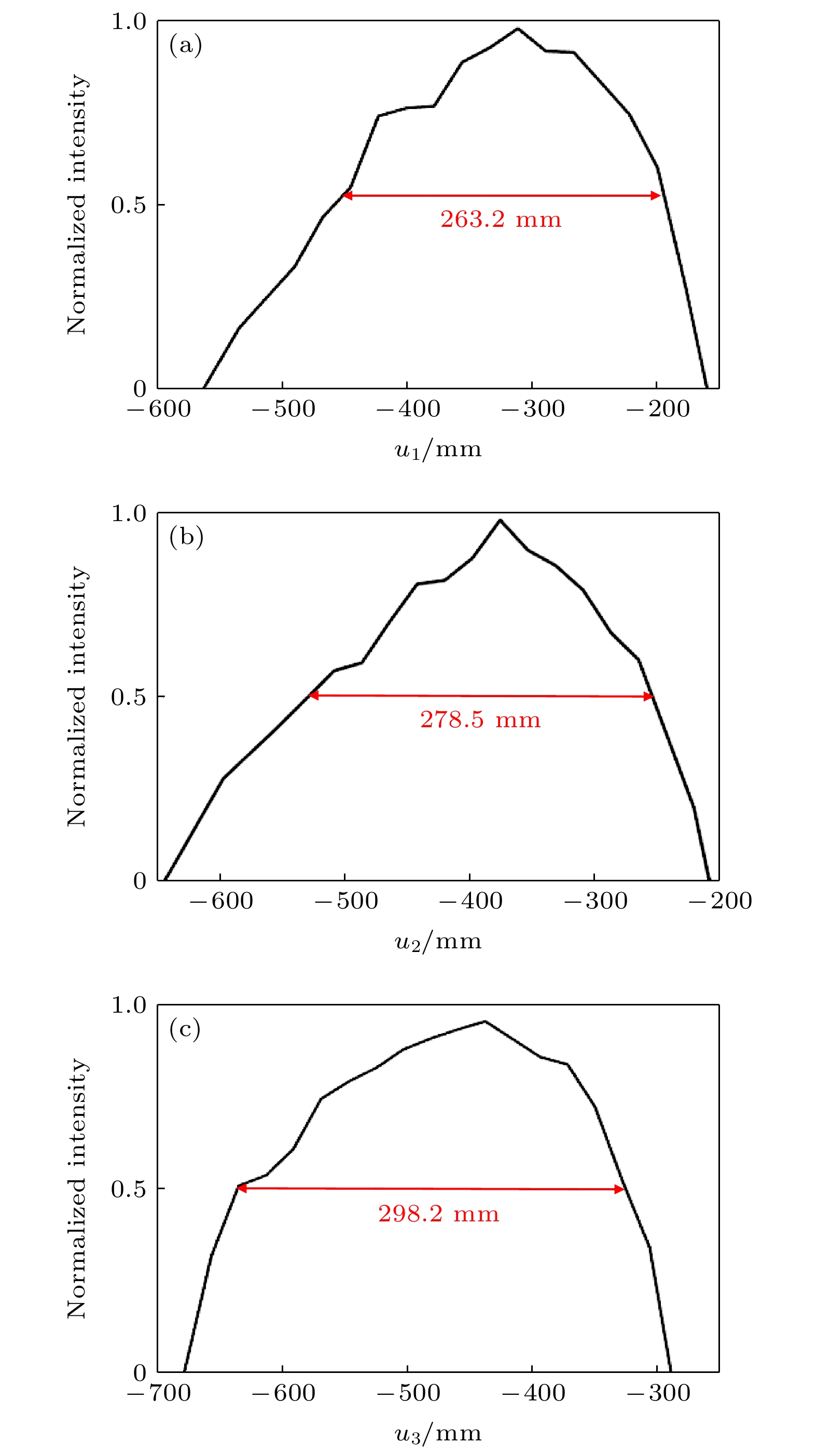 图 6 测试得到的不同频率处的焦深 (a) 8 GHz; (b) 9 GHz; (c) 10 GHz
Figure6. Depth of focus at different frequencies: (a) 8 GHz; (b) 9 GHz; (c) 10 GHz.
| 入射波频 率/GHz | 仿真结果 | 实验结果 | |||||
| α/(°) | F0/mm | DOF/mm | α/(°) | F0/mm | DOF/mm | ||
| 8 | 33.2 | 302.5 | 223.6 | 30.5 | 278.9 | 263.2 | |
| 9 | 30.0 | 350.0 | 241.9 | 27.5 | 335.4 | 278.5 | |
| 10 | 26.8 | 385.3 | 254.3 | 23.6 | 400.2 | 298.2 | |
表1离轴超透镜的仿真结果和实验结果比较
Table1.Simulation and experimental results of the off-axis metalens.
由表1可知, 离轴偏转角的实验结果与仿真结果的误差在10%左右, 焦距的误差在10%以内, 焦深的误差在15%左右. 特别地, 在预设的工作频率f0 = 9 GHz处, 测试得到的聚焦点在z方向上的距离F0 = 335.4 mm、离轴偏转角α = 27.5°、焦深DOF = 278.5 mm; 与预设值(F0 = 350 mm, α = 30°, DOF = 241.9 mm)相比, 虽然存在偏差, 但是符合得较好.
误差来源主要有以下几点:
1)发射天线发射出的电磁波是球面波, 只有在距离发射天线很远的地方才可以被看作平面波. 但在测量中, 由于测试环境所限, 发射天线距离测试样品不是足够远, 因而样品实际接受到的并非是严格的平面波. 而仿真中采用的是平面波.
2)微波测试系统本身的误差. 例如, 微波暗室中的吸波材料配备不够完全, 会有部分电磁波反射到样品上. 此外, 在实验测试过程中, 采样数据点间距过大也导致了实验误差.
3)由于制作加工容差, 实际制备出的样品参数与仿真参数之间有误差. 例如FR4的厚度、介电常数等.
在后续的研究中, 课题组将完善测试条件, 搭建更加适合这种微波段大焦深离轴超透镜的测试实验平台. 虽然本文工作波段是微波波段, 但是根据超表面的尺寸缩放效应, 基于该方法也可以设计光波段、太赫兹等其他波段的大焦深离轴超透镜.
真诚地感谢课题组已经毕业工作的令永红师兄的贡献, 他在博士期间的工作为这篇文章提供了理论思路.
