全文HTML
--> --> -->由于光在角锥棱镜内反射的过程中有着复杂的偏振和相位变化[2-6], 反射光的远场能量分布往往与几何方法估算的结果差别很大. 此外携带反射器的卫星或航天器通常以极高的速度飞行, 卫星激光测距时由于速度光行差的影响, 反射光束的指向中心通常会显著偏离地面观测站[7,8]. 因此, 在反射器设计中, 准确的角锥棱镜远场衍射图样(far field diffraction pattern, FFDP) 仿真计算对于优化反射器的雷达散射截面具有重要的指导意义, 已成为评价反射器性能的重要分析手段. 国内外****已在该领域做了大量的研究工作, Chang等[9]在1971年就开展了无镀膜角锥棱镜的远场衍射研究; Arnold[2,10]也较早开展了角锥棱镜光学特性的研究, 完成了角锥棱镜在多种参数下的远场衍射分析; Otsubo等[11]在对激光测月反射器的研究中分析计算了不同镀膜类型和不同口径的角锥棱镜远场衍射图样; Sadovnikov和Sokolov[3]建立了完整的无镀膜角锥棱镜的完全内反射偏振态转化模型, 得到了经实验验证的无镀膜角锥棱镜远场衍射; 声远[4,12]、钟声远等[13]和周辉等[5,6,14]从多个角度在数学上描述了角锥棱镜的FFDP计算原理, 给出了多种情况圆切割角锥棱镜的远场衍射计算结果. 然而国内外对角锥棱镜的FFDP研究大多考虑的是激光垂直入射的情况, 对激光倾斜入射的FFDP的规律性分析较少, 也较少对比多种入射方向下镀膜和非镀膜角锥棱镜FFDP的区别.
本文分析了多种入射角度下镀金属膜和无镀膜角锥棱镜的反射特点, 分析了影响角锥棱镜在多种入射方向(多为斜入射)下的FFDP的有效反射面积和光学反射率与入射角的关系, 提出了一种适用于多种切割方式的有效反射面积计算方法. 结合有效反射面积和反射率计算, 建立了角锥棱镜的远场衍射计算模型, 计算了多种入射角度的角锥棱镜的FFDP. 结合远场衍射实验测量结果, 对比得到不同镀膜情况的角锥棱镜在多种入射角度光作用下的远场衍射分布规律, 验证了仿真模型计算结果, 对于角锥棱镜有效反射面积的计算以及远场衍射的仿真研究具有一定的参考和借鉴意义.
2.1.角锥棱镜的反射机理
如图1(a), 简化角锥棱镜的反射面为3个两两垂直的平面, 令入射光线矢量为


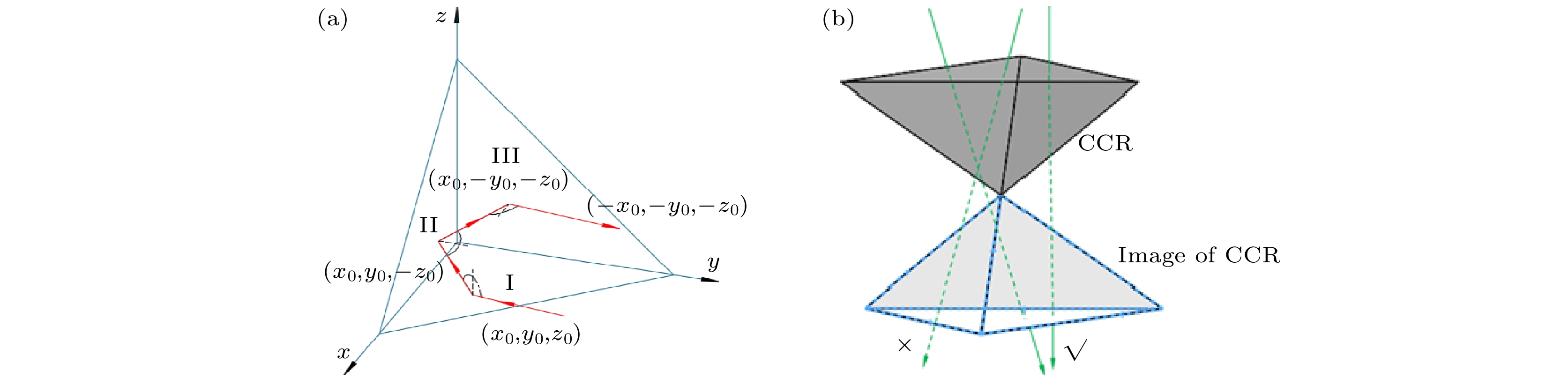 图 1 (a)光线在经过CCR后向反射后的方向矢量变化; (b)光线在CCR中完成后向反射的条件
Figure1. (a) Change of ray’s direction vector retro-reflected by CCR; (b) condition of rays reflected backwards by CCR.
为追迹角锥棱镜内部光线, 可将角锥棱镜的3个反射面按照反射顺序依次对棱镜空间进行3次镜像折叠, 理想角锥棱镜(反射面两两垂直)的六种反射次序对应的镜像都是与角锥棱镜顶点中心对称的同一个虚像, 如图1(b). 不论光线的反射顺序如何, 只要入射光线于角锥透射面孔径内入射, 同时光线延长线也自镜像透射面孔径出射时, 光线就满足后向反射的条件[15]. 符合后向反射条件的反射光截面面积就是有效反射面积, 是衡量后向反射光能量的一个重要标准, 具体将在2.2节讨论.
2
2.2.有效反射面积与入射光方向的关系
角锥棱镜的有效反射面积决定了完成后向反射的光束宽度. 根据角锥棱镜切割后的透射面孔径形状, 角锥棱镜大致分为两类: 圆形切割和六边形切割角锥棱镜.定义角锥棱镜切割系数


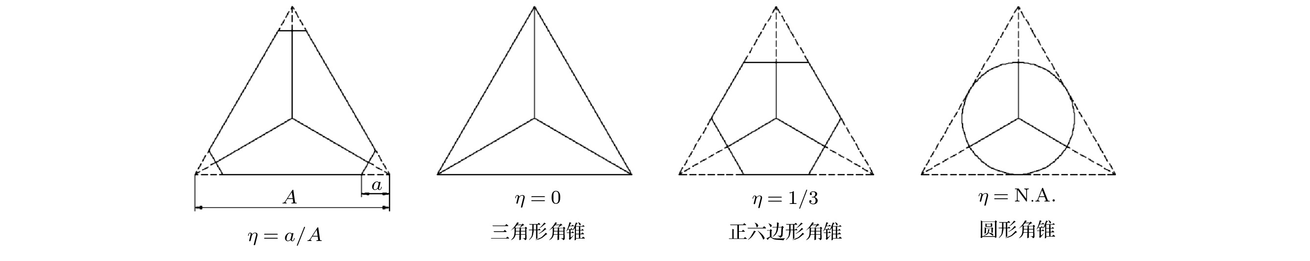 图 2 角锥棱镜的各种切割方式
Figure2. Cutting modes of various CCR.
圆形切割是一种最常见的角锥棱镜切割方式, 结构紧凑、稳定性好、易堆叠. 目前绝大多数卫星激光反射器采用了圆形切割角锥棱镜. 关于圆形切割角锥的有效反射面积计算, 众多研究者已给出了任意入射角度下的面积计算方法[2,12]. 六边形切割的角锥棱镜在入射方向上看是120o旋转对称的, 具有很好的对称性, 适合密集的阵列式排布, Lunokhod系列月球反射器和我国的TG-1交会对接激光雷达反射器都采用了六边形或三角形角锥棱镜阵列设计. 由于六边形切割的有效反射面积与入射角度和切割系数均有关系, 需要讨论的情况非常多. 文献[2,12,16,17]给出了三角形切割角锥的任意入射角度的有效反射面积和正六边形切割角锥的特定入射角度的有效反射面积计算公式. 但国内外研究中, 对任意切割系数的六边形角锥在任意入射角度下的有效反射面积计算方法并未见诸文献.
本文则针对包括六边形角锥在内的常见角锥棱镜给出了一种计算任意切割系数和任意入射角度的有效反射面积的方法. 可统一计算包括六边形、三角形和圆形等全部常见形状角锥棱镜的任意入射角度的有效反射面积.
以三角形切割的角锥棱镜为例, 当光以一定的角度入射到角锥棱镜时, 以入射光与透射平面法线的夹角为入射角θ, 透过角锥前表面后折射角为θ′, 入射光在透射平面上的投影与该平面坐标轴的夹角为方位角φ, 角锥棱镜的顶高为h, 角锥棱镜前表面孔径的镜像与其投影的重叠面积为D, 见图3.
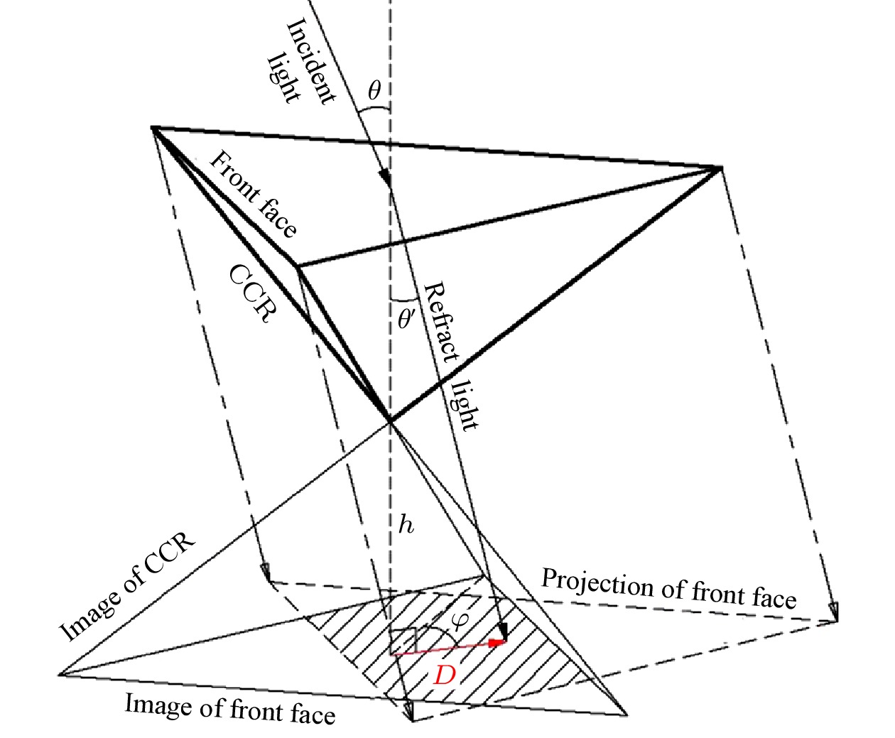 图 3 角锥棱镜的镜像和投影孔径的重叠决定了有效反射面积
Figure3. Active reflecting area determined by the overlap of image and projection of CCR front face.
根据2.1节描述, 角锥棱镜孔径沿折射光线方向的投影与角锥棱镜入射面镜像在底面的重叠部分为满足后向反射的有效反射区域, 如图3阴影部分, 计算其在入射光方向的截面积可得到角锥棱镜在该入射方向的有效反射面积.
令有效反射面积为S, 可得到如下关系:


更一般地, 讨论六边形切割的投影情况. 在角锥棱镜孔径镜像所在平面上建立平面直角坐标系, 如图4, 角锥棱镜孔径的投影与镜像的边界均可用直线方程描述, 重叠部分即可用平面面积积分求得. 首先, 同样设切割前角锥棱镜入射面三角形边长为


 图 4 六边形角锥的重叠面积
Figure4. Overlapped area of hexagonal CCR.
特别地, 当切割系数

如图5所示, 以边长60 mm的熔石英(

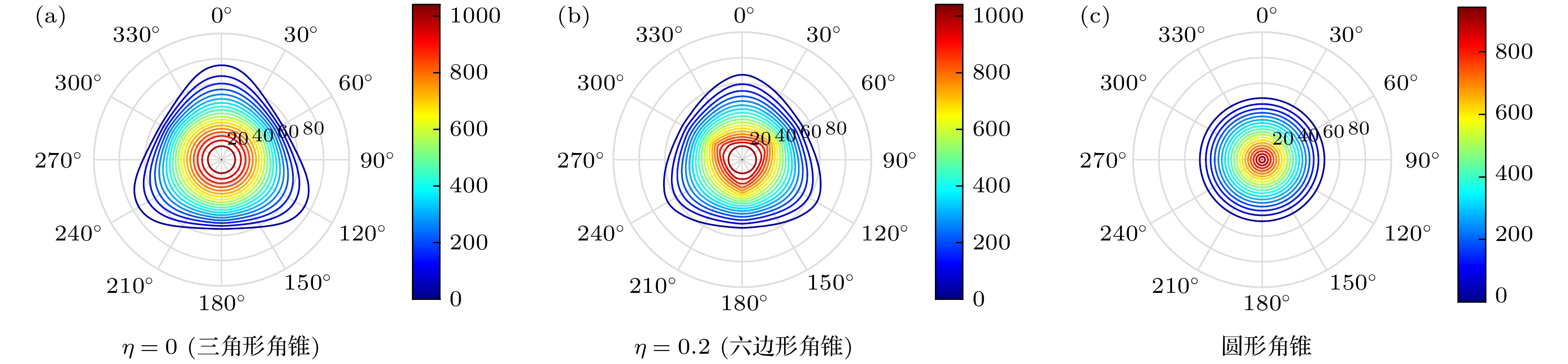 图 5 不同形状角锥棱镜有效反射面积(mm2)随入射角(θ, 0o?90o)和方位角(φ, 0o?360o)的分布
Figure5. CCR active reflecting area in dependence of incidence and azimuth angle for different cutting mode. Polar axis refers to incident angle (θ, 0o?90o) in degree, the other axis refers to azimuth angle (φ, 0o?360o) in degree, the color bar refers to the active reflecting area in square millimeter
2
2.3.光学反射率与入射光方向的关系
角锥棱镜的光学反射率决定了一定入射光光强条件下, 经过角锥棱镜反射后的出射光光强, 与有效反射面积一起共同决定了角锥棱镜反射的光能量.根据菲涅尔公式[18], 介质表面的反射率总是与入射角有关, 角锥棱镜的总光学反射率需要考虑三次内反射的综合效果. 以三角形角锥为例, 根据图3的坐标定义, 角锥棱镜的入射光线总是以入射角


本文主要讨论最常见的反射面无镀膜和镀金属膜两种情况. 金属反射膜的不同种类(如金、银、铝)和膜层厚度对光学反射率和FFDP均有一定的影响, 本文对此不做详细讨论, 后文关于镀金属膜的仿真和实验主要针对镀银膜.
对于镀金属反射膜的角锥棱镜来说, 因为常见金属反射膜对可见光波段在很大的入射角范围内具有较高的反射率, 高效率的后向反射产生的条件比较容易满足. 如图6, 将折射光矢量的终点移动到角锥顶点, 以绿色箭头表示, 矢量只要处在3个垂直阴影面包围的同一侧即可达到高效率的后向反射效果. 因此, 对于镀金属膜的角锥棱镜来说, 光束斜入射时的入射角主要通过影响有效反射面积影响反射器整体的反射能力, 光线经过角锥棱镜的总光学反射率受入射角度影响相对较小.
 图 6 金属膜角锥棱镜满足高效率后向反射的折射光线矢量
Figure6. High efficiency backward reflection ray vector in metal-coated CCR.
对于无镀膜角锥棱镜, 光线的反射原理为完全内反射, 在符合全反射条件时可以以更高的反射率传递光能量, 而当光线与某反射面法线的夹角小于全反射角时, 总反射能量则急剧下降, 破坏了角锥整体的高效率后向反射状态.
令角锥材料折射率为


 图 7 无镀膜角锥棱镜满足高效率后向反射的折射光线矢量
Figure7. High efficiency backward reflection ray vector in uncoated CCR.
以熔石英(折射率约1.461)材料的镀银膜和无镀膜三角形角锥棱镜分析为例, 参考图3、图6和图7的入射角


镀金属膜角锥满足高效率后向反射条件的入射角度范围在图8(a)的红色实线围住的部分. 最大折射角


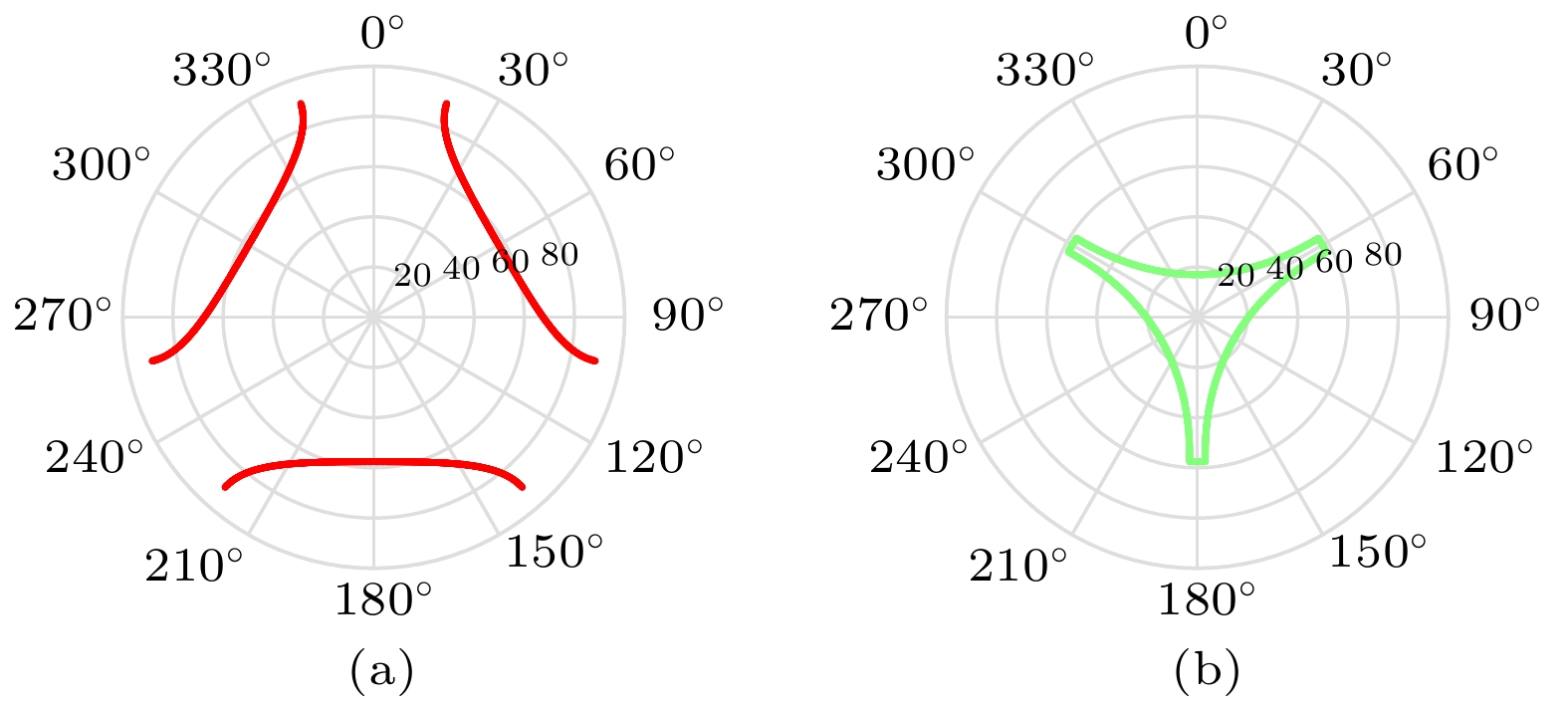 图 8 (a)镀金属膜与(b)无镀膜角锥棱镜(n ≈ 1.44@1550 nm)的高反射率入射方向范围
Figure8. High optical efficiency incidence direction range of (a) metal-coated and (b) uncoated CCR (n ≈ 1.44@1550 nm)
无镀膜角锥满足高效率后向反射条件的入射角度范围在图8(b)的绿色实线围住的部分. 最大折射角


由图8可知, 镀金属膜和无镀膜的角锥棱镜满足高效率后向反射条件的入射方向范围均呈现120°旋转对称特点, 但范围差别较大, 镀金属膜角锥具有相对更大的高反射率入射方向范围, 且高反射率的方位分布与无镀膜角锥棱镜互补. 尽管入射方位对反射率有影响, 但由图5可知, 在入射角较大时角锥棱镜的有效反射面积所剩无几, 因此此时的高反射率并没有多少实际意义.
2
2.4.远场衍射图样与入射光方向的关系
有效反射面积和反射率反映了角锥棱镜反射光能量的多少, 而地面测站最终能接收到的能量除此之外还取决于反射光的远场能量的分布, 即FFDP.依据光的标量衍射理论, 利用根据基尔霍夫衍射公式的弗朗禾费近似形式, 远场光强:


建立光波在反射器中入射、反射和出射的模型[19], 考虑入射光波长和偏振态、材料折射率、反射面镀膜等参数, 同时将光线斜入射的有效反射面积、孔径形状以及反射率变化根据上文分析计入模型中, 应用(4)式, 得到角锥棱镜在多种入射方向下的FFDP仿真图样.
以应用最广泛的圆切割角锥为例, 在假设无二面角偏差(即无角锥体加工角度误差)的情况下, 仿真了1550 nm线偏振激光入射到直径33 mm反射面镀银膜角锥棱镜在不同入射角度下的FFDP图样.
结果显示, 镀银膜角锥棱镜的FFDP图样大体上呈现艾里斑的形状, 当光以一定入射角度经过角锥棱镜反射时, 远场衍射图样由圆对称的艾里斑逐渐沿入射面拉伸, 并且强度变弱. 激光入射角越大, 有效反射面积越小, 角锥棱镜的远场衍射能量越弱, 能量分布越分散. 同时图样会向有效反射区域收窄的方向拉伸, 如图9所示. 多个入射方向的仿真结果显示, 镀银膜角锥棱镜的FFDP与入射光方位角和光偏振方向均无关系.
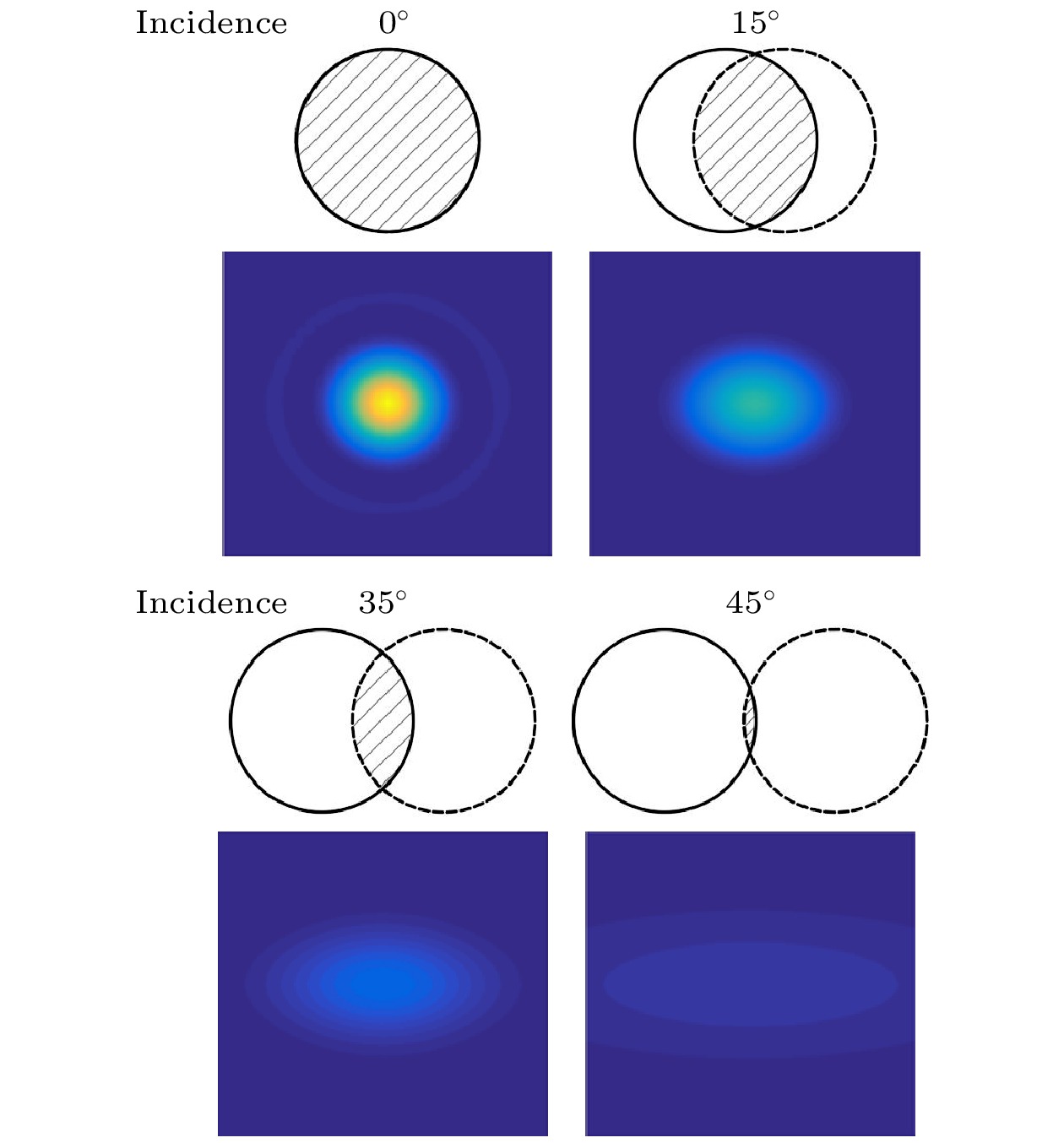 图 9 镀银膜角锥棱镜不同入射角的FFDP (图样范围约
Figure9. FFDP of Ag-coated CCR in various incidence direction.
无镀膜的角锥棱镜, 在假设无二面角偏差的情况下, 不同入射角度的1550 nm线偏振激光入射到直径33 mm无镀膜角锥棱镜的FFDP图样如图10, 由于无镀膜角锥的FFDP与偏振态高度相关, 计算中统一假设入射光为偏振方向平行于入射面的线偏振光.
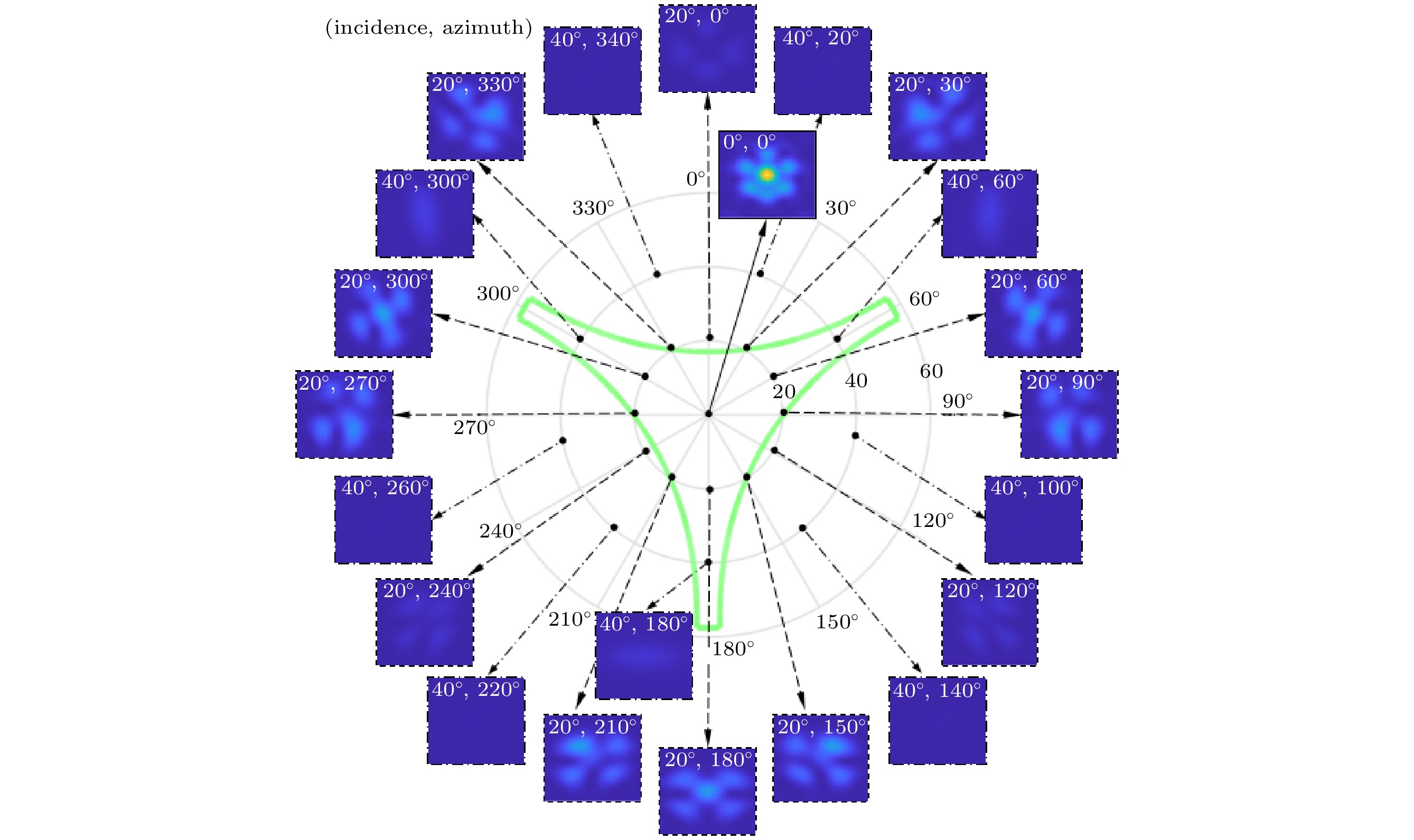 图 10 无镀膜角锥在不同入射方向的FFDP
Figure10. FFDP of uncoated CCR in various incidence direction.
从图10可以看出, 即使没有二面角偏差, 无镀膜角锥棱镜的FFDP图样仍然与艾里斑有很大不同, 能量被不对称地分成几个光瓣, 其大小、数量和分布与光入射方向、光的偏振态均有关系.
依靠全反射原理作用的无镀膜角锥棱镜, 其FFDP强度较大的入射方向基本处在图5(c)所示的大反射面积范围和图8(b)所示的高光学反射率范围内. 尽管依图5(c)所示, 圆形切割的角锥棱镜的有效反射面积与入射方位无关, 但由于无镀膜角锥棱镜不同入射方位的光学反射率差别较大, FFDP强度还是体现出了明显的方位相关性. 具体表现为图10中同样为入射角20°的所有方位中, 0°, 120°和240°方位角的FFDP强度显著弱于其他方位, 相对地, 同样为入射角40°的所有方位角中, 60°, 180°和300°方位角的FFDP强度则强于其他方位.
总的来说, 以银膜为代表的镀金属膜角锥棱镜通常更有利于低轨卫星反射器这一类激光入射角度变化大的应用环境. 对于无镀膜角锥棱镜来说, 光斜入射时的入射方向除影响有效反射面积以外对光线反射率影响较大, 符合后向反射条件的截止入射角并不是固定不变的, 而是与入射方位有关, 在特定的方位无镀膜角锥也可以对较大角度的入射光实现高效率的后向反射. 但总体来说适用于高轨卫星反射器或月球反射器这种激光入射角度变化较小的情况[20-22].
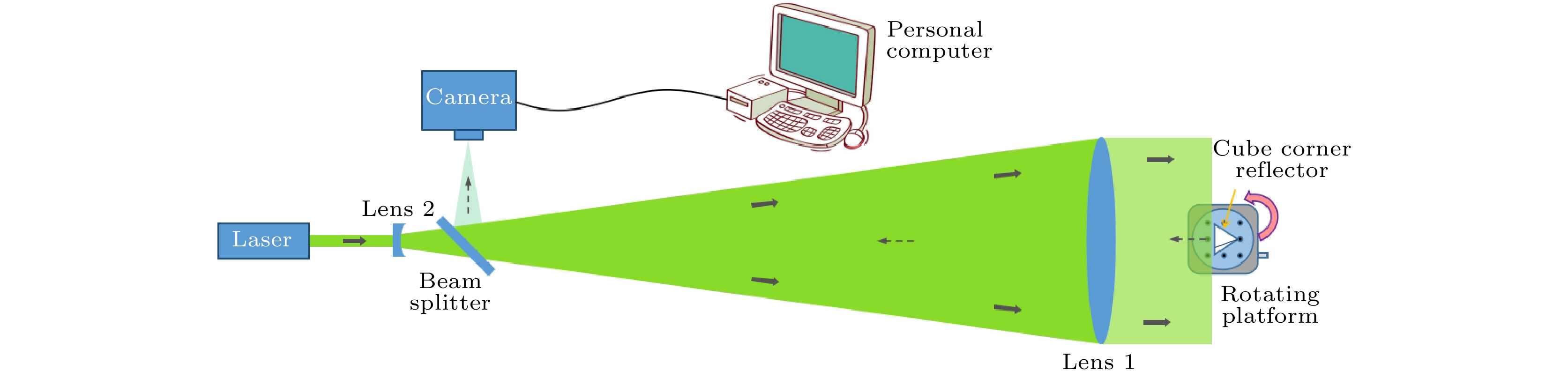 图 11 角锥棱镜的FFDP测量系统
Figure11. A measurement system of the CCR’s FFDP.
测试角锥棱镜1: 熔石英材料(

 图 12 不同入射角镀银膜角锥的FFDP仿真与实测结果对比(图样范围约60′′ × 60′′)
Figure12. Comparison of FFDP simulation and experimental results of metal coated CCR with different incident angles (The drawing range is about 60′′ × 60′′).
测试角锥棱镜2: 熔石英材料(n ≈ 1.44@1550 nm), 圆切割, 通光口径为33 mm, 反射面无镀膜处理, 二面角偏差(1.7′′/1.8′′/1.5′′), 入射激光为某方向线偏振态1550 nm激光. 任意选取两种入射方向和偏振方向情况进行了FFDP测量和仿真计算结果的对比, 如图13所示.
 图 13 不同入射角无镀膜角锥的FFDP仿真与实测结果对比(图样范围约60′′ × 60′′)
Figure13. Comparison of FFDP simulation and experimental results of uncoated CCR with different incident angles (the drawing range is about 60′′ × 60′′).
无镀膜角锥棱镜的FFDP更复杂, 除与棱镜形状、口径、折射率、激光波长等因素相关外, 还与入射激光偏振态有关[5,19,23]. 从图13可以看到, 仿真结果与实测结果吻合得较好. 远场衍射能量同样随入射角增大而减弱, 能量分布随入射角变化发生形状变化且受偏振方向影响明显. 在实测中某一方位入射角达到20o时仍有一定强度的远场能量分布, 验证了2.4节的分析.
