全文HTML
--> --> -->

双曲超构材料可进一步分为电双曲超构材料和磁双曲超构材料, 二者的区别在于是介电张量还是磁导率张量的三个分量中既有正值又有负值. 由于光波段的磁响应比较难以实现, 所以位于光波段的电双曲超构材料比磁双曲超构材料更为普遍. 对于单轴的电双曲超构材料, 在主轴坐标系下, 其介电张量可以表示为


另一方面, 由不同材料周期性排列而成的光子晶体的光传输特性的调控引起了研究人员的广泛关注, 涵盖了带隙调控、通带调控和群速度调控等各个方面[32-35]. 近年来, 宇称-时间(parity-time, PT)对称的光子晶体也引起了人们的关注[36-39]. 基于PT对称的光子晶体, 可以实现多种新奇的光学现象, 包括奇异点(exceptional point)劈裂[36]、奇异点合并[37]、各向异性的反射振荡[38]和单方向隐身[39]等. 光子带隙是光子晶体的一个核心特征, 对光子晶体的带隙调控是目前光物理的一个活跃领域[32-35]. 频率落在带隙中的光, 将无法在光子晶体中稳定传播, 从而被光子晶体强烈反射[40,41]. 三十多年来, 光子晶体的带隙被广泛地应用在各个方面[42,43], 如激光器[44-46]、滤波器[47-49]、传感器[50,51]、偏振分束器[52,53]、光波导[54,55]、光纤[56-58]、高方向性天线[59]、单向传输[60-62]和自发辐射调控[63]等. 目前, 通常组成光子晶体原胞的材料的等频面都具有相同的封闭拓扑结构, 其中结构最为简单的是由两种各向同性介质交替组成的一维光子晶体. 然而, 这种传统的光子晶体的带隙强烈依赖于光的入射方向[64-68]. 在TM和横电(transverse electric, TE)偏振下, 各向同性的电介质的等频线均为封闭的圆. 因此, 在固定频率下, 光子晶体原胞内的总传播相位将随着入射角的增大而减小. 为了维持布拉格反射条件(即原胞内的总传播相位等于π的整数倍)的成立, TM和TE偏振的带隙随着入射角的增大将会向高频(短波)方向移动(即蓝移)[64-68]. 传统的全介质一维光子晶体带隙的蓝移特性, 将使得全向带隙的宽度小于正入射时的带隙宽度, 从而不利于全向带隙的产生和展宽[64-68]. 此外, 对于TM和TE偏振, 传统带隙都是随入射角蓝移的, 这将导致带隙对不同偏振的区分度不明显, 从而限制了偏振选择的工作角度范围. 此外, 光子晶体带隙的蓝移特性还将导致金属/光子晶体异质结中的光学界面态的蓝移特性[69,70], 从而使得基于光子带隙的一些应用(如近完美光吸收[71-73]和超灵敏传感[74-76])限制在很窄的入射角度范围内. 综上所述, 由具有相同拓扑结构的等频面的材料组成的光子晶体具有一系列的缺点. 因此, 一个很有趣的问题是, 由具有不同拓扑结构的等频面的材料组成的复合周期结构对光子带隙的形成机制有何影响?
本文将介绍本研究组近年来在含双曲超构材料的复合周期结构的带隙调控及其应用方面的研究情况. 这种新型的复合周期结构如图1所示. 目前, 双曲超构材料主要可由两种方式实现. 一种方式是由二维金属柱阵列实现[77,78]. 此时, 复合周期结构是由一个层状介电材料和二维金属柱阵列杂化而成的复合光子晶体. 另一种方式是由金属/介质亚波长多层膜实现[78-80]. 此时, 复合周期结构就是一个由多层膜构成的一维光子晶体. 一维结构的制备只需用到镀膜技术[81,82], 比二维和三维结构简单许多[43,83], 且更容易进行大面积的制备[84]. 此外, 一维光子晶体的应用十分广泛, 包括宽带反射镜[64,85-90]、宽带透明[91,92]、宽带波片[93]、窄带滤波器[94-98]、窄带吸收器[71-73,99,100]、非互易传输[101-103]和辐射制冷[84]等. 因此, 本文将主要介绍课题组在这方面的研究情况.
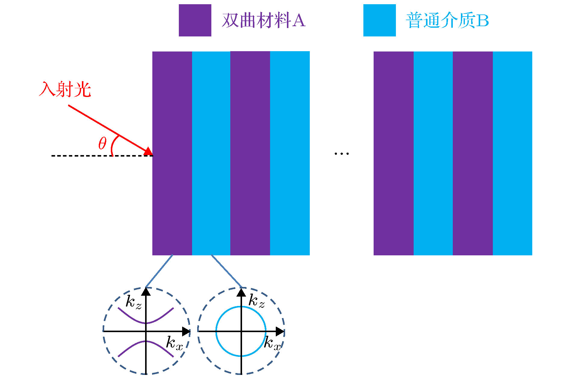 图 1 含双曲超构材料的复合周期结构的示意图
Figure1. Schematic of the compound periodic structure containing hyperbolic metamaterials.
 图 2 传统的全介质一维光子晶体(AB)N的示意图
Figure2. Schematic of the conventional all-dielectric one-dimensional photonic crystal (AB)N.


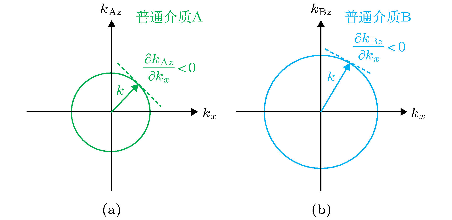 图 3 普通介质A和B的等频线(TM和TE偏振)
Figure3. Iso-frequency curves of isotropic dielectrics A and B (TM and TE polarizations).
因此,


下面给出一个具体的例子. 图4给出了数值计算的一维光子晶体(AB)10的反射谱(TM和TE偏振)随入射角的变化, 其中蓝色虚线为带隙的两个边缘, 由最靠近带隙的反射极小值提取. A和B层的材料分别为SiO2和TiO2, 折射率分别为1.43和2.12[104]. A和B层的厚度满足四分之一波堆条件


 图 4 数值计算的一维光子晶体(AB)10的反射谱(TM和TE偏振)随入射角的变化
Figure4. Calculated reflectance spectrum of (AB)10 as a function of incident angle (TM and TE polarizations).
由图4可知, 无论是对于TM还是TE偏振而言, 传统的全介质一维光子晶体的带隙均随着入射角的增大而蓝移. 如引言所述, 传统一维光子晶体TM和TE偏振带隙的蓝移特性, 不仅不利于全向带隙的产生和展宽, 还大大限制了偏振选择、近完美光吸收以及超灵敏传感的工作角度范围.
3.1.带隙调控的理论基础
为了克服传统的全介质一维光子晶体的物理限制, 构造了由双曲超构材料和介质交替组成的一维新型光子晶体, 如图5所示. 其中, 双曲超构材料由金属/介质亚波长多层膜等效而成. 根据等效介质理论, 金属/介质亚波长多层膜在某个特定的频段可等效为单轴的电双曲超构材料, 其等效相对介电张量的两个分量为[2-5] 图 5 含双曲超构材料的一维光子晶体[(CD)SB]N的示意图
Figure5. Schematic of the one-dimensional photonic crystal containing hyperbolic metamaterials [(CD)SB]N.


 图 6 (a)双曲材料A和(b)普通介质B的等频线(TM偏振)
Figure6. Iso-frequency curves of (a) hyperbolic metamaterial A and (b) isotropic dielectric B (TM polarization).
由图6可知,


2
3.2.零移带隙
零移带隙即与角度无关的带隙, 这种带隙不随入射角的增大而移动. 因此, 根据布拉格条件, 光子晶体原胞的总传播相位


 图 7 含双曲超构材料的一维光子晶体[(CD)2B]3在不同入射角下的反射谱(TM偏振) (a) 数值计算结果[107]; (b) 实验测量结果[107]
Figure7. Reflectance spectra of [(CD)2B]3 under different incident angles (TM polarization): (a) Simulated result[107]; (b) experimental result[107].
由数值计算结果可知, 带隙的长波长边缘几乎与入射角无关, 然而短波长边缘随入射角有轻微的移动, 这是由于在设计中, 近似条件


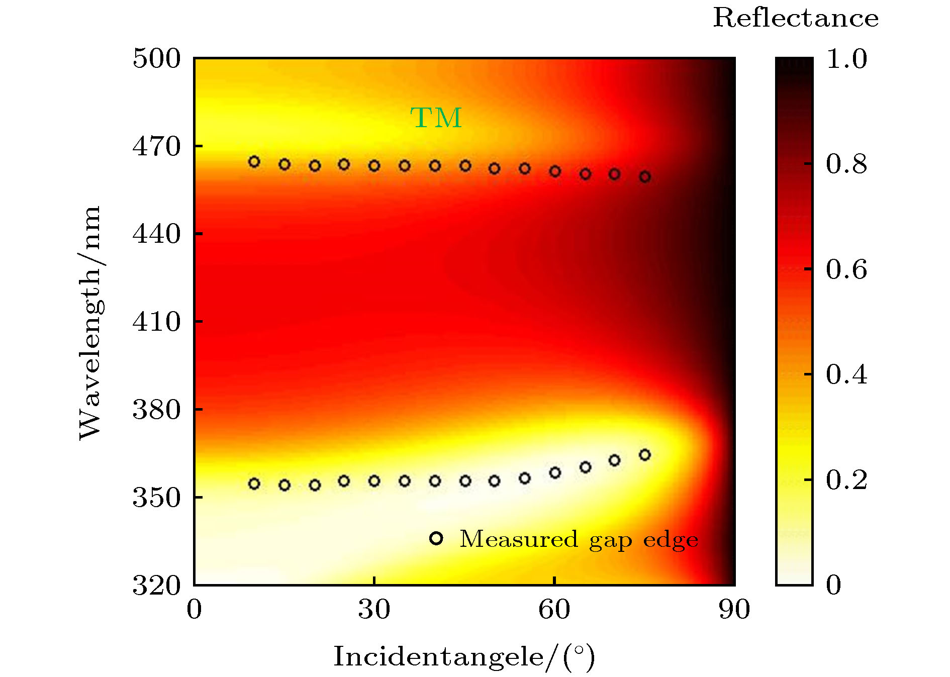 图 8 含双曲超构材料的一维光子晶体[(CD)2B]3的反射谱(TM偏振)随入射角的变化[107], 其中彩色背景代表数值计算结果, 黑色空心圆圈代表实验测量的带隙边缘(由最靠近带隙的反射极小值提取)
Figure8. Reflectance spectrum of [(CD)2B]3 as a function of incident angle (TM polarization)[107]. Background color represents the calculated result. Black hollow circle represents measured gap edge extracted from the reflectance dip.
由图8可知, 当入射角从10°增大到75°时, 测量的带隙短波长边缘从355 nm轻微移动到了365 nm, 长波长边缘始终位于462 nm附近. 因此, 得到了一个位于可见光波段的近乎零移的全向带隙, 其范围约为365—460 nm. 这一与入射角无关的带隙为我们设计具有固定带宽的全向反射器提供了新的机理.
2
3.3.红移带隙
红移带隙即随入射角的增大而红移的带隙. 要获得红移带隙, 根据布拉格条件, 光子晶体原胞的总传播相位


根据方程(9), 设计了具体的多层膜结构, 结构式为[(CD)2B]3. 选取的正入射时的布拉格波长

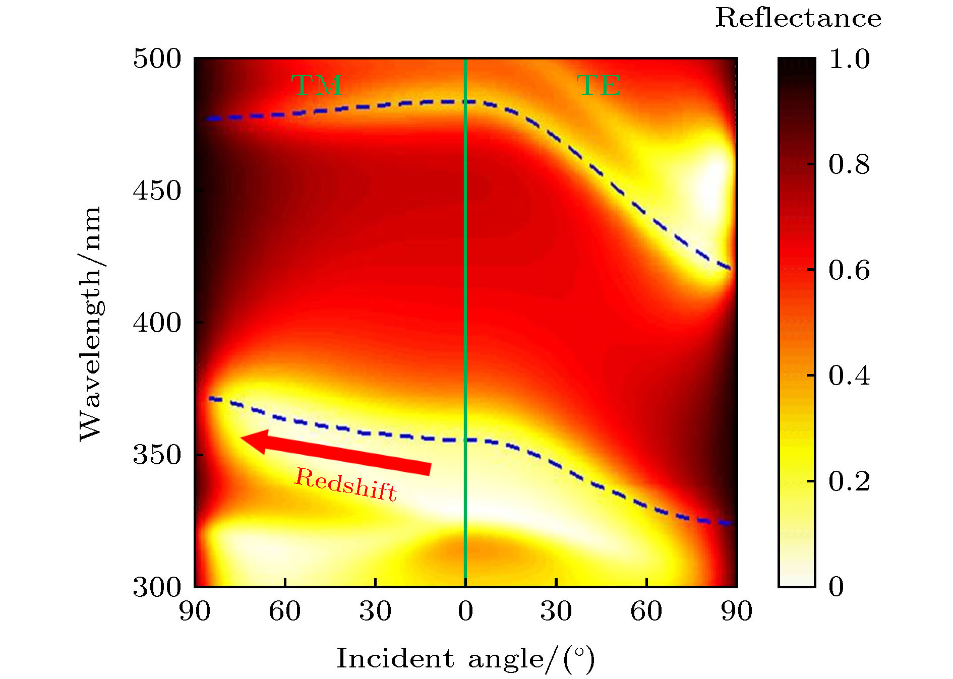 图 9 数值计算的含双曲超构材料的一维光子晶体[(CD)2B]3的反射谱(TM和TE偏振)随入射角的变化[108]
Figure9. Calculated reflectance spectrum of [(CD)2B]3 as a function of incident angle (TM and TE polarizations)[108].
由图9可知, 对于TM偏振而言, 带隙的短波长边缘随着入射角的增大而红移, 这与我们的理论设计相符. 然而, 带隙的长波长边缘并没有随着入射角的增大而红移, 这是由于长波长边缘落在了(CD)2的第一类双曲区域之外[108]. 对于TE偏振而言, 带隙的两个边缘均随着入射角的增大而蓝移. 因此, 在短波长边缘处, 两种偏振的带隙随入射角增大的走向相反. 这一特性可用于实现宽角度的偏振选择, 详见4.2节.
图10给出了相应的实验测量结果[108]. 其中图10(a)和图10(b)分别代表TM和TE偏振的反射谱测量结果. 实心圆点代表最靠近带隙的反射极小值(即带隙边缘的标定位置), 灰色阴影区域代表带隙的短波长边缘随入射角的波动范围.
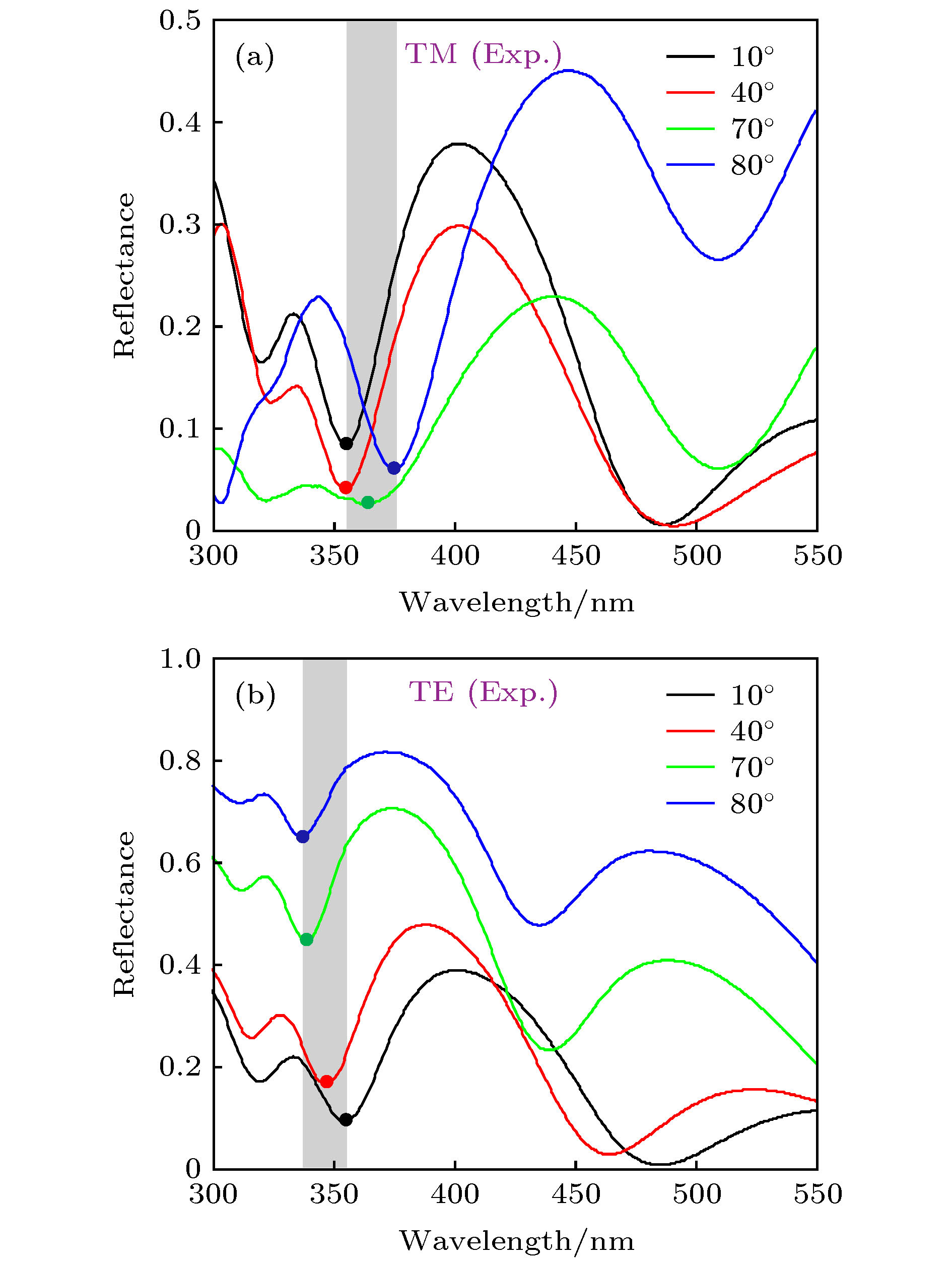 图 10 实验测量的含双曲超构材料的一维光子晶体[(CD)2B]3在不同入射角下的反射谱 (a) TM偏振[108]; (b) TE偏振[108]
Figure10. Experimental reflectance spectra of [(CD)2B]3 under different incident angles: (a) TM polarization[108]; (b) TE polarization[108].
由图10可知, 随着入射角的增大, 实验测得的TM偏振下的带隙的短波长边缘是红移的, 而TE偏振下的带隙的短波长边缘则是蓝移的. 在第4节中, 将介绍上述两种新型带隙—零移带隙和红移带隙的三个具体应用.
4.1.基于零移带隙的宽角度近完美光吸收器
利用金属/全介质一维光子晶体异质结中的光学界面态的场局域特性, 可实现近完美的光吸收[71-73]. 然而, 由于全介质一维光子晶体带隙随入射角蓝移的特性, 异质结中的界面态也将随着入射角的增大而蓝移, 这大大限制了近完美光吸收的工作角度范围[71-73]. 在3.2节中, 利用含双曲超构材料的一维光子晶体实现了随入射角零移的带隙. 若将金属和具有零移带隙的光子晶体组成新型的异质结, 将可实现对入射角不敏感的光学界面态, 从而大大拓宽近完美光吸收的工作角度范围[109].异质结的结构式为M[(CD)2B]3, 结构示意图如图11(a)所示[109]. 其中M为金属层, 其材料为Ag. [(CD)2B]3为含双曲超构材料的一维光子晶体, 其中C和B层的材料为TiO2, D层的材料为Ag. 入射和衬底介质分别为空气和BK7玻璃. 图11(b)给出了实验测量的异质结在不同入射角下的吸收谱(TM偏振)[109].
 图 11 (a) 异质结M[(CD)2B]3的结构示意图[109]; (b) 实验测量的异质结M[(CD)2B]3在不同入射角下的吸收谱(TM偏振)[109]
Figure11. (a) Schematic of the heterostructure M[(CD)2B]3[109]; (b) experimental absorptance spectra of M[(CD)2B]3 under different incident angles (TM polarization)[109].
从图11(b)可以看出, 近完美吸收峰对入射角不敏感. 当入射角从7.5°增大到45°时, 吸收峰从386.5 nm轻微移动到了376 nm, 较好地继承了带隙对入射角不敏感的特性. 图12进一步给出了实验测量的在波长380 nm处的吸收率随入射角的变化(TM偏振)[109].
 图 12 实验测量的异质结M[(CD)2B]3在波长380 nm处的吸收率随入射角的变化(TM偏振)[109]
Figure12. Experimental absorptance of M[(CD)2B]3 as a function of incident angle at

由图12可知, 在波长380 nm处, 随着入射角从7.5°增大到45°, 吸收率始终保持在90%以上. 因此, 基于零移带隙, 我们有效地拓宽了金属/一维光子晶体异质结的近完美光吸收的工作角度范围, 实现了宽角度的近完美光吸收.
从应用来看, 基于金属/介质亚波长多层膜的单个双曲超构材料也可实现近完美光吸收, 但它只能工作在很窄的角度范围内[110]. 有研究人员利用双曲超构材料阵列结构, 例如将由金属/介质亚波长多层膜金字塔结构等效而成的双曲超构材料排成一维阵列, 实现了宽角度的近完美光吸收[31,111]. 这种阵列结构对制备技术的要求较高. 而我们利用一维复合周期结构实现了宽角度的近完美光吸收. 相比阵列结构, 这种多层膜复合结构更容易制备.
2
4.2.基于红移带隙的宽角度偏振选择器
如引言所述, 对于TM和TE偏振, 传统的全介质一维光子晶体的带隙都是随入射角的增大而蓝移的, 这将导致带隙对不同偏振的区分度不明显, 从而限制了偏振选择的工作角度范围. 在3.2节, 在含双曲超构材料的一维光子晶体中实现了TM偏振的红移带隙和TE偏振的蓝移带隙. 因此, 在带隙的短波长边缘处, 由于两种偏振的带隙随入射角增大的走向相反, 可用于实现宽角度的偏振选择. 图13(a)给出了实验测量的含双曲超构材料的一维光子晶体[(CD)2B]3的TM和TE偏振在带隙的短波长边缘
 图 13 (a) 实验测量的含双曲超构材料的一维光子晶体[(CD)2B]3在波长365 nm处的TM和TE偏振的反射率随入射角的变化[108]; (b) 相应的偏振选择比随入射角的变化[108]
Figure13. (a) Experimental reflectance of M[(CD)2B]3 as a function of incident angle for TM and TE polarizations at

由图13(a)可知, 随着入射角的增大, 波长365 nm处TE偏振的反射率逐渐增大而TM偏振的反射率始终维持在较低的水平. 图13(b)给出了相应的偏振选择比

从实现偏振分光的功能而言, 已有研究人员从理论上利用双曲超构材料的等频面的偏振依赖特性实现了宽角度的偏振选择[112]. 尽管这个工作中用到的结构是金属/介质亚波长多层膜, 但其偏振选择机制决定了膜的界面方向与入射波矢的切向分量垂直, 即光需要从多层膜的侧面入射. 由于侧面的尺寸限制, 实验上测量分光将有一定的困难. 虽然我们的结构也是多层膜结构, 但是膜的界面方向与入射波矢的切向分量平行, 即光从多层膜的正面入射. 这在实验上易于测量分光. 当然, 由于我们的结构含有多层双曲超构材料, 结构对光的吸收比较多, 会在一定程度上降低偏振选择比.
2
4.3.基于红移带隙的宽角度折射率传感
近年来, Tsurimaki等[75]研究人员利用金属/全介质一维光子晶体异质结的光学界面态, 实现了基于椭偏相位(TM和TE偏振的反射相位之差)的超灵敏温度传感. 在斜入射下, 异质结在TM和TE偏振下的界面态波长将会不同, 从而导致椭偏相位在TM或TE偏振的界面态波长附近发生剧变, 进而导致了传感的高灵敏性[75]. 然而, 由于全介质一维光子晶体在TM和TE偏振下的带隙都是随入射角的增大而蓝移的, 导致异质结在TM和TE偏振下的界面态也是蓝移的[74-76]. 在小角度入射下, 异质结在TM和TE偏振下的界面态的波长差别很小, 从而降低了传感的灵敏度[74-76]. 因此, 对于传统的异质结, 具有高灵敏度的传感的工作角度范围较小. 在集成光学系统中, 入射光源往往具有一定的波束宽度和角发散性, 这将导致传感的灵敏度的进一步降低[113]. 在3.2节, 我们在含双曲超构材料的一维光子晶体中实现了TM偏振的红移带隙和TE偏振的蓝移带隙. 因此, 若将金属和这种特殊的光子晶体组成新型的异质结, 将可实现在TM偏振下红移而在TE偏振下蓝移的光学界面态, 从而大大拓宽具有高灵敏度的传感的工作角度范围[114].新型异质结的结构式为M[(CD)2B]9, 其中M为金属层, 其材料为Cu. [(CD)2B]9为含双曲超构材料的一维光子晶体, 其中C和B层的材料为Si, D层的材料为ITO (氧化铟锡). 入射和衬底介质分别为空气和BK7玻璃. 图14给出了数值计算的异质结M[(CD)2B]9的反射谱(TM和TE偏振)随入射角的变化[114]. 其中蓝色虚线为带隙的两个边缘, 由最靠近带隙的反射极小值提取. 红色虚线代表界面态, 由带隙中的反射极小值提取.
 图 14 数值计算的异质结M[(CD)2B]9的反射谱(TM和TE偏振)随入射角的变化[114]
Figure14. Calculated reflectance spectrum of M[(CD)2B]9 as a function of incident angle (TM and TE polarizations)[114].
由图14可知, 对于TM偏振而言, 界面态随着入射角的增大是红移的, 而对于TE偏振而言, 界面态则是蓝移的. 因此, 即使在小角度入射下, TM和TE偏振的界面态的波长差别也比较显著, 传感的灵敏度可以得到保证[114]. 我们在异质结的下方放置了一个溶液池, 溶液池中放置折射率待测的溶液, 如图15(a)所示[114]. 图15(b)给出了数值计算得到的传感器的最佳折射率分辨率随入射角的变化[114]. 由图15(b)可知, 传感器在入射角从5°到84°的范围内的最佳折射率分辨率均小于

 图 15 (a) 折射率传感器的示意图[114]; (b) 数值计算的传感器的最佳折射率分辨率随入射角的变化[114]
Figure15. (a) Schematic of the refractive index sensor[114]; (b) calculated minimal refractive index resolution as a function of incident angle[114].
从应用来看, 利用双曲超构材料的大波矢模式也可实现宽角度的超灵敏折射率传感[29]. 但是大波矢模式的激发需要用到光栅耦合[29]或棱镜耦合[30]. 而我们结构的传感机制则是利用了光学界面态, 其色散关系位于光锥线以上, 可直接被从空气中入射的平面波激发. 当然, 我们的结构含有多层双曲超构材料, 双曲超构材料中的损耗会在一定程度上降低传感的灵敏度.
