Key Laboratory of Electromagnetic Wave Science and Detection Technology in Fujian Province, Institute of Electromagnetics and Acoustics, Xiamen University, Xiamen 361005, China
Abstract:The perfectly matched layer plays a key role in electromagnetic simulations, and it makes the infinite space look like a finite space, so that the electromagnetic waves propagating to the boundary seem like their propagations to the infinity. The inner perfectly matched layer has a similar concept, usually in the form of a cylinder or sphere placed inside the physical field. It makes the electromagnetic field matched at the boundary, so that the electromagnetic waves propagate on its convex surface as if they were propagating to an infinite distance, without any scattering. In addition to the perfectly matched layer, planar absorbers can be realized in a variety of ways, such as spatial Kramers-Kronig relations, photonic crystals, metamaterials, etc. On the other hand, the inner cylindrical or spherical absorbers are generally perfect absorbers, electromagnetic “black hole”, etc. Transformation optics always arouse great research interests. For its property of controlling propagation of electromagnetic waves arbitrarily under coordinate mappings, transformation optics has a wide range of applications and has also been used as a theoretical tool for designing absorbers. However, to the authors’ knowledge, there is no effective method to achieve perfect absorption of inner absorbers with no reflections and independence of incident angle or wave frequency. In this paper, transformation optics theory is used to design an inner perfectly matched layer whose material parameters are obtained by a radial coordinate transformation of the complex plane. Through investigating the electromagnetic wave patterns and the two-dimensional far-field diagrams, we intuitively compare and analyse one by one the absorption characteristics of the matched and mismatched perfect absorber, electromagnetic “black hole” and the inner perfectly matched layer. It is found that the matched perfect absorber has better absorption property than mismatched one and electromagnetic “black hole”. In the electromagnetic “black hole” there appear a lot of scatterings. While our inner perfectly matched layer demonstrates the best effectiveness of absorption with no back scattering. It can be used as an absorbing kernel in electromagnetic simulations and relevant experiments. Keywords:inner perfectly matched layer/ transformation optics theory/ electromagnetic “black hole”/ absorption characteristics
通过运用多物理场仿真软件COMSOL Multiphysics, 得到两组参数下的吸收体对从右侧入射的平面波的电磁响应, 如图1(a)和图1(b)所示. 在外围设置常用的柱状完美匹配层有效吸收各个方向的电磁波而无反射, 中间柱体设置完美吸收体的两组参数, 全文中吸收体的外边界均设置为4 m. 可以看出, 平面波在接触到中间吸收体之后被吸收, 在左侧留下与该柱体截面相似大小的阴影区域. 与之分别对应的远场对比图由图1(c)给出, 远场图的中间放大部分可见图1(d). 由此可清楚地发现, 两组参数的吸收体前向散射基本一致, 其吸收性能相差不大, 但对于后向散射, 由于第二组参数($\varepsilon = 1+0.5 {\rm i}, \mu = 1$) 相对于第一组参数($\varepsilon = 1+{\rm i}, \mu = 1$)匹配性更好, 即$\sqrt{\mu/\varepsilon}$比值更接近1, 所以其反射更小, 后向散射更少. 图 1 两个完美吸收体的吸收及散射特性对比图 (a) 吸收体 ($\varepsilon=1+{\rm i}, \mu=1$) 的电场强度图; (b) 吸收体 ($ \varepsilon=1+0.5 {\rm i}, \mu=1$) 的电场强度图; (c) 两个吸收体的远场分布对比图; (d) 两个吸收体的远场分布对比放大图 Figure1. Comparison diagram of absorption and scattering characteristics of two perfect absorbers: (a) The electric field intensity diagram of absorber ($ \varepsilon=1+{\rm i}, \mu=1$); (b) the electric field intensity diagram of absorber ($ \varepsilon=1+0.5 {\rm i}, \mu=1$); (c) the comparison diagram of the far field distribution of the two absorbers; (d) the comparison diagram of the enlarged far field distribution of the two absorbers
其吸收及散射特性与阻抗不匹配的情况对比远场图如图2所示. 图 2 不同完美吸收体的吸收特性对比 (a), (b) 1组吸收体阻抗匹配与不匹配的远场对比图和远场对比放大图; (c), (d) 2 组吸收体阻抗匹配与不匹配的远场对比图和远场对比放大图; (e), (f)两组阻抗匹配的吸收体的远场对比图和远场对比放大图 Figure2. Absorption characteristics comparison of different perfect absorbers: (a) The far field comparison diagram and (b) far field comparison enlarged diagram of impedance-matched and impedance-mismatched absorbers of the first set; (c) the far field comparison diagram and (d) far field comparison enlarged diagram of impedance-matched and impedance-mismatched absorbers of the second set; (e) the far field comparison diagram and (f) far field comparison enlarged diagram of impedance-matched absorbers of the above two sets
$\varepsilon(r) = \begin{cases} 1, & r > 4, \\ {{(4/r)}^2}, & 2 < r < 4,\\ 4(1 + {\rm i}),& r < 2,\end{cases} \quad \mu = 1.$
由于材料是非磁性的, $ \mu $均为1, 此时材料参数阻抗不匹配, 由图3(a)的电场幅值图和图3(c)的电场z分量图可以看到此时的电磁“黑洞”对入射的平面波具有很明显的后向散射. 若改进此电磁“黑洞”的吸收性能, 设定阻抗匹配的介电常数和磁导率表达式如下: 图 3 电磁“黑洞”吸收特性分析 (a) 阻抗不匹配和(b) 阻抗匹配的电磁“黑洞”电场强度图; (c) 阻抗不匹配和(d) 阻抗匹配的电磁“黑洞”电场z分量图; 阻抗不匹配和阻抗匹配的电磁“黑洞”的(e) 远场对比图和(f) 远场对比放大图 Figure3. Analysis of absorption characteristics of electromagnetic “black hole”: The electric field intensity diagram of (a) impedance-mismatched and (b) impedance-matched electromagnetic “black hole”; the electric field z component diagram of (c) impedance-mismatched and (d) impedance-matched electromagnetic “black hole”; (e) the far field comparison diagram and (f) far field comparison enlarged diagram of impedance-mismatched and impedance-matched electromagnetic “black hole”
$ \epsilon (r) = \mu (r) = \begin{cases} 1,& r > 4,\\ 4/r,&2 < r < 4,\\ 2(1 + {\rm i}),& r < 2,\end{cases} $
4.完美吸收体、电磁“黑洞”与内置完美匹配层的吸收特性对比在分析了完美吸收体和电磁“黑洞”的吸收特性之后, 还不能确定二者性能谁优谁劣, 为此, 本文继续对比二者的电场远场图. 分别对阻抗不匹配和阻抗匹配的完美吸收体和电磁“黑洞”进行对比, 如图4(a)和图4(b)所示, 阻抗不匹配的二者, 后向散射均比较大, 完美吸收体比电磁“黑洞”的散射更均匀一些, 且总体散射更少些; 而对于阻抗匹配的二者, 整体散射场均比阻抗不匹配的二者小得多, 同样地, 完美吸收体比电磁“黑洞”的散射更均匀一些, 总体散射也少得多, 场更集中紧密一些, 如图4(c)和图4(d)所示. 有趣的是, 仔细地观察图4(c)远场图的最左端会发现, 阻抗匹配的二者中, 完美吸收体的前向散射场幅值更大, 从另一个角度说明了其吸收更多, 方向性也更好, 这些特性可能是因为电磁“黑洞”不是由变换光学直接导出所致. 图 4 完美吸收体与电磁“黑洞”吸收特性对比 (a), (b)阻抗不匹配的完美吸收体和电磁“黑洞”的远场对比图和远场对比放大图; (c), (d)阻抗匹配的完美吸收体和电磁“黑洞”的远场对比图和远场对比放大图 Figure4. Absorption characteristics comparison of perfect absorber and electromagnetic “black hole”: (a) The far field comparison diagram and (b) far field comparison enlarged diagram of impedance-mismatched perfect absorber and electromagnetic “black hole”; (c) the far field comparison diagram and (d) far field comparison enlarged diagram of impedance-matched perfect absorber and electromagnetic “black hole”
这即为本文采用的内置完美匹配层的介质材料表达式. 从表达式中可以看出, 这其实是一组带吸收的负折射材料, 具有非均匀且各向异性的特点, 相比于Horsley等[3]提出的各向同性的Kramers-Kronig材料, 也是在实验中相对较难实现的材料. 但是, Kramers-Kronig材料目前只能运用于平面的吸收材料, 而本文需要一个凸柱面的吸收材料, 就本文作者所知, 这种柱面的Kramers-Kronig材料还未得到真实有效的研究成果. 另一方面, 本文是利用变换光学得到的各向异性的材料, 这类材料与隐身衣材料类似, 因此利用开口谐振环实现的隐身衣的实验[16]也可作为本文内置完美匹配层材料在实验中实现的参考. 同样地, 画出平面波入射至此内置完美匹配层的电场强度及其z分量分别如图6(a)和图6(b)所示, 可以明显地看出平面波被吸收, 虽然在吸收界面上有一点电场被增强的效果, 但整体看不出有明显的肉眼可见的反射. 为了更好地展现其吸收性能, 进一步将其与匹配的完美吸收体和电磁“黑洞”做远场对比, 结果如图6(c)—(f)所示, 可以发现内置完美匹配层的后向散射几乎没有, 仔细观察图6(c)和图6(e)最左边端点处会发现, 内置完美匹配层前向散射比另外二者幅值更大, 说明吸收效果更好. 综上所述, 内置完美匹配层的后向散射最小, 吸收幅度最大, 作为吸收体来讲, 其吸收性能是最好的, 这也充分体现了变换光学在吸收体设计中起到了非常重要的作用. 图 6 完美吸收体、电磁“黑洞”与内置完美匹配层(inner PML)的吸收特性对比 (a), (b)内置完美匹配层的电场强度图和电场z分量图; (c), (d)阻抗匹配的完美吸收体和内置完美匹配层的远场对比图和远场对比放大图; (e), (f)阻抗匹配的电磁“黑洞”和内置完美匹配层的远场对比图和远场对比放大图 Figure6. Absorption characteristics comparison of perfect absorber, electromagnetic “black hole” and inner PML: (a) Electric field intensity diagram and (b) electric field z component diagram of inner PML; (c) far field comparison diagram and (d) far field comparison enlarged diagram of impedance-matched perfect absorber and inner PML; (e) far field comparison diagram and (f) far field comparison enlarged diagram of impedance-matched electromagnetic “black hole” and inner PML


 图 1 两个完美吸收体的吸收及散射特性对比图 (a) 吸收体 (


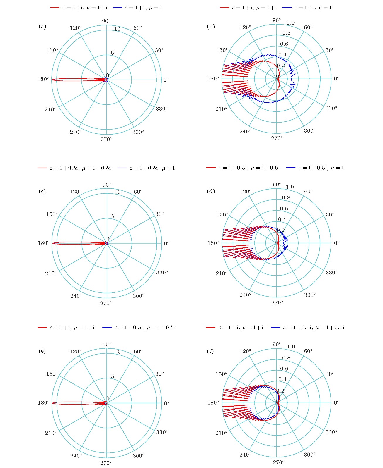 图 2 不同完美吸收体的吸收特性对比 (a), (b) 1组吸收体阻抗匹配与不匹配的远场对比图和远场对比放大图; (c), (d) 2 组吸收体阻抗匹配与不匹配的远场对比图和远场对比放大图; (e), (f)两组阻抗匹配的吸收体的远场对比图和远场对比放大图


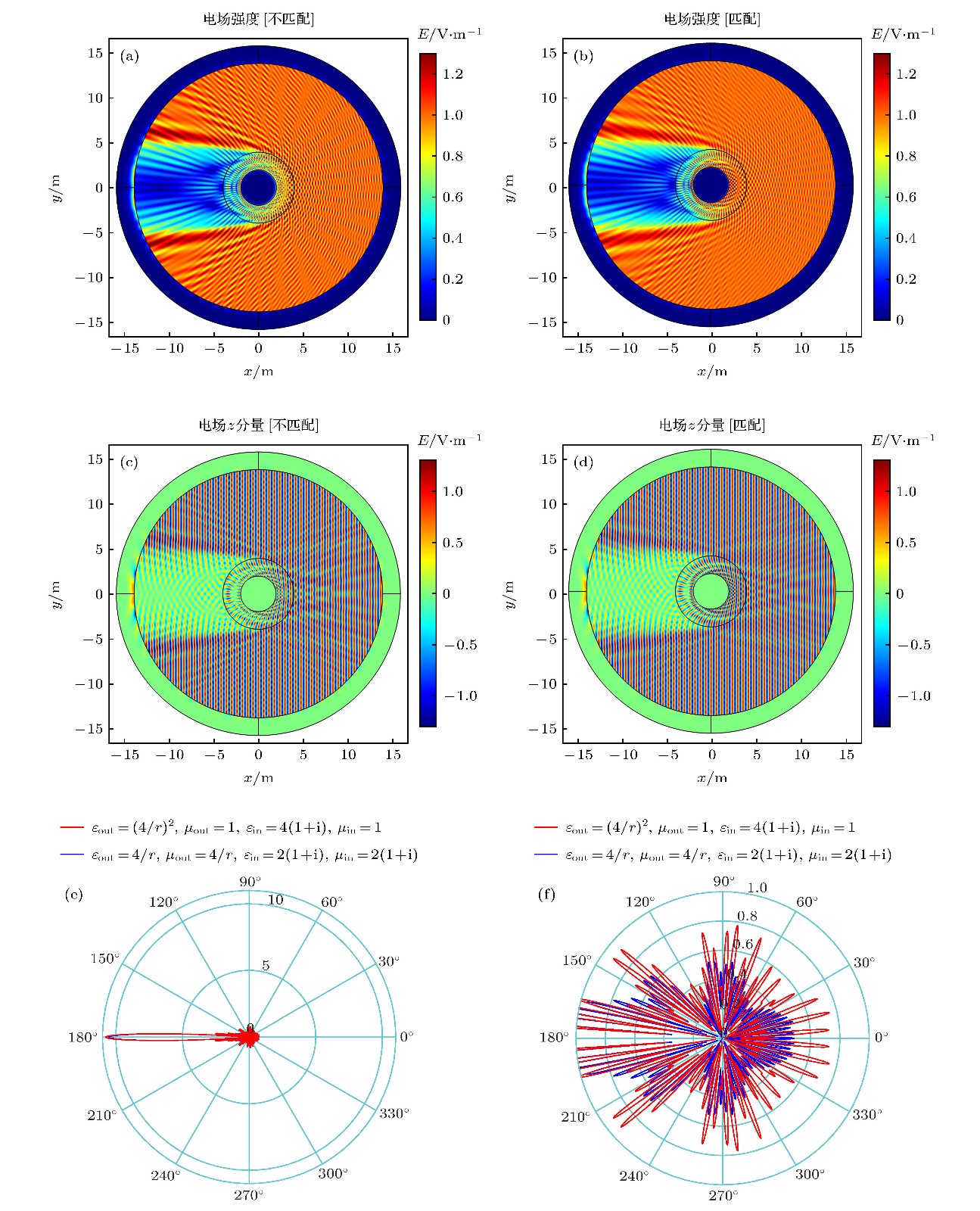 图 3 电磁“黑洞”吸收特性分析 (a) 阻抗不匹配和(b) 阻抗匹配的电磁“黑洞”电场强度图; (c) 阻抗不匹配和(d) 阻抗匹配的电磁“黑洞”电场z分量图; 阻抗不匹配和阻抗匹配的电磁“黑洞”的(e) 远场对比图和(f) 远场对比放大图
 图 4 完美吸收体与电磁“黑洞”吸收特性对比 (a), (b)阻抗不匹配的完美吸收体和电磁“黑洞”的远场对比图和远场对比放大图; (c), (d)阻抗匹配的完美吸收体和电磁“黑洞”的远场对比图和远场对比放大图


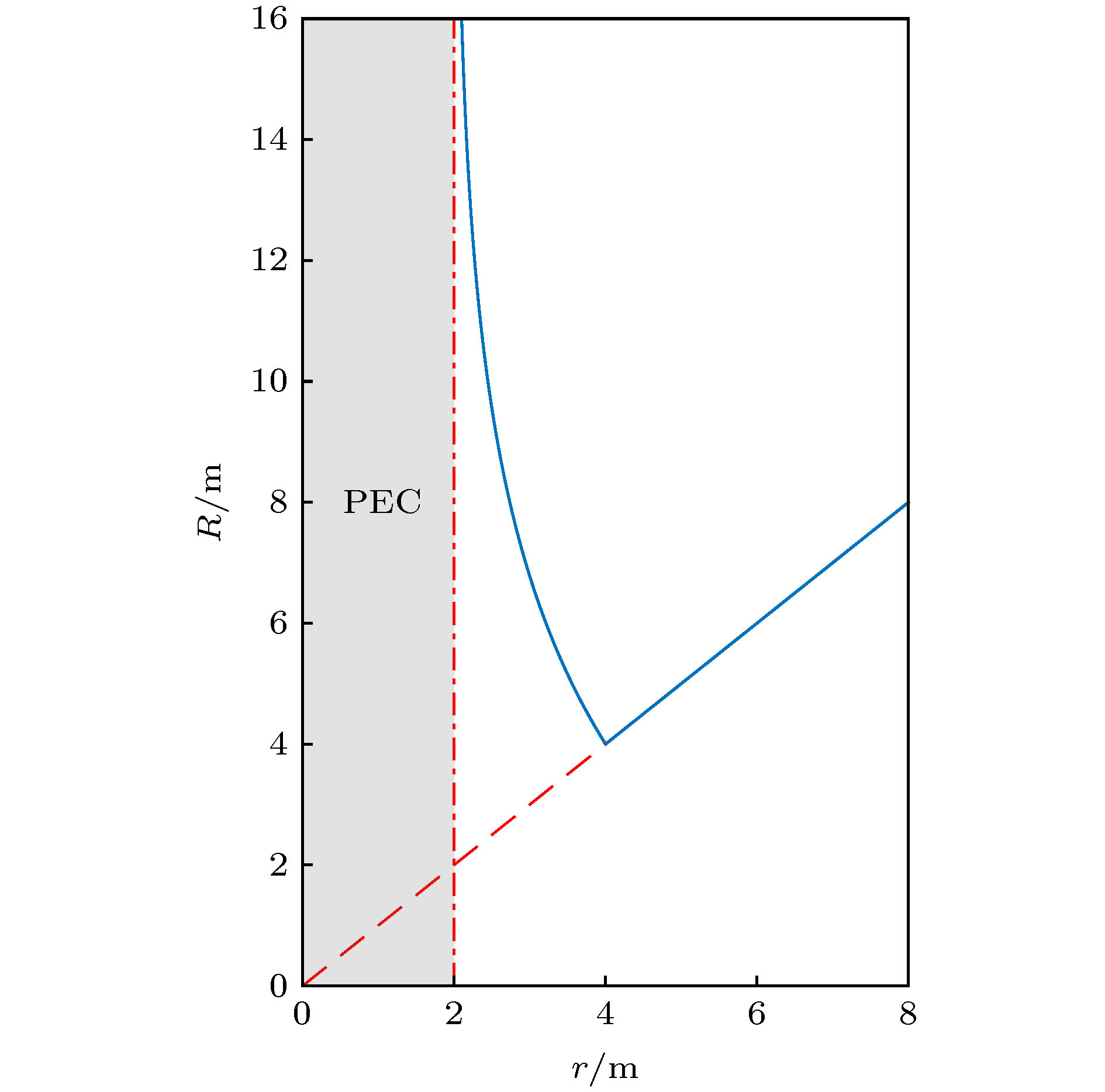 图 5 径向变换关系曲线
 图 6 完美吸收体、电磁“黑洞”与内置完美匹配层(inner PML)的吸收特性对比 (a), (b)内置完美匹配层的电场强度图和电场z分量图; (c), (d)阻抗匹配的完美吸收体和内置完美匹配层的远场对比图和远场对比放大图; (e), (f)阻抗匹配的电磁“黑洞”和内置完美匹配层的远场对比图和远场对比放大图