Laboratory of Science and Technology on Integrated Logistics Support, College of Intelligence Science and Technology, National University of Defense Technology, Changsha 410073, China
Abstract: The topologically protected edge states of elastic waves in phononic crystal plates have the outstanding characteristics in wave manipulation such as the strong suppression of back-scattering and defect immunity, which can be used for controlling vibration and noise, detecting the structural damage, conducting the material nondestructive test and other engineering practices, and therefore have received much attention. But for plate structures, the propagation of elastic waves is complicated due to the coexistence and coupling of different types of wave modes, resulting in a challenge in designing topologically protected states. In this paper, a simple phononic crystal plate with triangular holes is designed for elastic wave manipulation based on topologically protected edge states. The band structure characteristics of the unit cell are studied by varying the rotation angle θ of the triangular holes around their geometric centers from the initial positions. It is found that the band structure of the initial unit cell with rotation angle θ = 0° has two pairs of degenerate modes. At $ \theta = \pm 33^\circ $, a double Dirac cone appears at the center Γ point of the Brillouin zone without requiring the lattices to fold, and a band inversion occurs on both sides of $ \pm 33^\circ $ which can be characterized as a topological phase transition. The elastic band gap and two kinds of pseudospin states with clockwise or counterclockwise circulating mechanical energy flux patterns in the band structure are found by calculating the projected band structures of a supercell which is composed of phononic crystals with different topological phases. Based on this finding, different constructions of phononic waveguide are used for implementing the numerical analysis to demonstrate the back-scattering immunity of the edge states when disorder, tortuosity and cavity are introduced into the waveguide. Unidirectional robust propagation and multichannel waveguide switch due to the pseudospin-dependent one-way edge modes are also validated with numerical models. The phononic crystal plate presented in this paper provides a simple realizable method of designing the topologically protected elastic edge states. Keywords:topological phase transition/ elastic wave-guide/ elastic topological edge states/ phononic crystals
本文通过在均匀基板上周期布列三角形穿孔, 构造了如图1(a)所示的声子晶体板结构, 其元胞构型如图1(b)所示, 晶体板厚度$h = 4.2\;{\rm{ mm}}$, 元胞晶格常数$a = 8.7\;{\rm{ mm}}$, 晶格基矢${{{a}}_1}$和${{{a}}_2}$可分别表示为${{{a}}_1}=a(1/2, \sqrt 3 /2)$和${{{a}}_2}=a(1, 0)$. 元胞中包含一组关于短对角线对称的等边三角形通孔, 其几何中心分别位于元胞长对角线的两个三等分点处, 三角形穿孔边长$l = 3.7\;{\rm{ mm}}$, 蓝色三角形穿孔代表通孔的初始位置, 本文通过将两个三角形穿孔同时围绕其各自几何中心逆时针旋转$\theta $角度, 得到新的元胞结构(如黄色三角形所示)并研究旋转角度对元胞能带特性的影响. 图1(c)为该元胞所对应的第一布里渊区, 红色区域为不可约布里渊区. 基板材料参数为: 杨氏模量$E = 3.8\;{\rm{GPa}}$, 泊松比$\sigma =0.4$, 密度$\rho =1180\;{\rm{ kg}}/{{\rm{m}}^3}$. 图 1 声子晶体板结构、元胞及其布里渊区示意图 (a) 具有三角形穿孔的声子晶体板结构; (b) 声子晶体板的元胞; (c) 晶格的第一布里渊区和不可约布里渊区(红色区域) Figure1. Schematic diagram of phononic crystal plate structure, its unit cell and corresponding Brillouin zone: (a) The phononic crystal plate structure with triangular through-holes; (b) the unit cell of the phononic crystal plate; (c) the first Brillouin zone and irreducible Brillouin zone (red region) of the lattice.
22.2.声子晶体能带特性 -->
2.2.声子晶体能带特性
本文中的三角形穿孔声子晶体板元胞的能带结构如图2所示. 对于该声子晶体板, 板中的弹性波有水平剪切模、对称型兰姆模和非对称型兰姆模, 水平剪切模是一种粒子运动方向只有x方向和y方向的横向模, 其对应的模态振型如图2(a)左侧所示. 板中水平剪切模与其他弹性波模具有本质上的不同, 体现在以下两方面[21]: 首先, 水平剪切模没有面外z方向运动分量, 而其他弹性波模同时具有x方向、y方向和面外z方向的运动分量(如图2(a)右侧对应的模态振型), 水平剪切模的拓扑性质和其他弹性波模不相关; 其次, 水平剪切模和其他弹性波模能够分别被独立的激发出来, 例如使用垂直板平面外(z方向)的激励作用在板上时, 能够激发其他弹性波模的同时抑制水平剪切模. 通过对能带结构中对应本征态的位移分布进行分析, 很容易将水平剪切模与其他模区分开来[40]. 为更加清晰地区分出水平剪切模态能带与其他模态的能带, 定义模态极化指标 图 2 三角形穿孔声子晶体板在不同旋转角度下的能带结构与本征态z方向位移场分布 (a) $\theta =0^\circ $, ${p_ \pm }$模位于${d_ \pm }$模下方, 左侧插图为${P_z}=0$点所对应的水平剪切模振型, 右侧插图为${p_ \pm }$和${d_ \pm }$模态的位移场分布和振型, 能带结构中用不同颜色表示${P_z}$极化指标; (b) $\theta =33^\circ $, 偶然简并形成双狄拉克锥, 右侧插图为${p_ \pm }$和${d_ \pm }$模态的位移场分布; (c) $\theta =60^\circ $, ${p_ \pm }$模位于${d_ \pm }$模上方 Figure2. Band structure and displacement field distribution (DFD) in z-direction at eigenstates of the phononic crystal plate with triangular holes with different rotation angle: (a) $\theta =0^\circ $, ${p_ \pm }$ modes are below ${d_ \pm }$ modes. The left DFD demonstrates mode shape of shear horizontal mode corresponding to the ${P_z}=0$ points, while the right group of DFDs illustrate the mode shapes of ${p_ \pm }$ and ${d_ \pm }$ modes. The color of the points on the dispersion curves corresponds to the ${P_z}$ polarization index; (b) $\theta =33^\circ $, a double Dirac cone is formed, and the right DFDs show eigenstates distributions of ${p_ \pm }$ and ${d_ \pm }$ modes; (c) $\theta =60^\circ $, ${p_ \pm }$ modes are above ${d_ \pm }$ modes.
将TTCs与TNCs拼合构造超元胞结构, 以研究其能带结构特性. 从图4(a)可以看出, 该超元胞由5个$\theta =0^\circ $的TTCs元胞与5个$\theta =60^\circ $的TNCs元胞沿着y轴方向拼合而成, 并将上下侧设置为低反射边界(low reflecting boundary, LRB)条件, 晶格基矢${k_x}$所示方向为周期性边界条件方向. 图4(b)为通过有限元方法计算得到的该超元胞能带结构, 结果表明弹性波在该超元胞边界中存在禁带, 范围为$8.249 \times {10^4} — 8.831 \times {10^4}\;{\rm{Hz}}$, 且在禁带内形成的一对不同赝自旋方向相关的拓扑边界态, 被分别用红色点和蓝色点标出. 值得注意的是, 图中带隙内存在灰色圆圈为水平剪切模, 它与其他弹性波模互不相关. 图 4 (a) 由5个TTCs与5个TNCs组成的超元胞; (b) 该超元胞的能带结构图, 其中红色和蓝色点代表边界态, A和B点为波矢${k_x} = \pm 0.2{\text{π}}/a$时对应的边界态, 灰色圆圈表示水平剪切模; (c) 图(b)中A和B点对应的z方向位移场分布, 放大图显示了边界态处的机械能量通量方向 Figure4. (a) Supercell composed of 5 TTCs and 5 TNCs; (b) the band structure of the supercell in (a), red and blue dots represent the edge states, A and B dots represent the pseudospin states in ${k_x} = \pm 0.2{\text{π}}/a$, and the gray circles represent the shear horizontal modes; (c) the DFDs in z-directiona corresponding to points A and B in (b), the enlarged figure shows the mechanical energy flux direction.
图4(c)为图4(b)中A和B点处边界态所对应的板平面外z方向位移场分布情况, 从图4(c)可以看出, 位移振幅的最大值集中在TNCs和TTCs拼合边界处, 并且向两侧迅速衰减, 因而位移被限制于超元胞边界处. 同时, 图4(c)中的放大图中标绘出超元胞边界态的机械能量通量方向, 分别呈现出顺时针或逆时针的分布情况. 事实上, 弹性波赝自旋态的物理意义可以由机械能流的循环模态表征, 该放大图揭示了A (B)点处具有逆时针(顺时针)机械能流循环模式的赝自旋+ (-)模态. 同时不同赝自旋方向相关的边界态能带斜率相反(即群速度相反), 则两种边界态具有相反的传播方向, 这表明存在赝自旋相关的弹性波单向传播. 3.基于拓扑边界态的稳健波导设计通过将TNCs与TTCs拼合构成超元胞, 在同一频率处得到了两种不同赝自旋方向的边界态, 这一性质能够被用于实现稳健的弹性波单向传播控制. 本文中利用垂直于声子晶体板方向(z方向)的振动源进行激励(如上文所分析, 这种方法能够激发出不包含水平剪切模的弹性波), 以进一步研究所设计的声子晶体板中弹性波的拓扑保护边界态. 首先, 利用两种不同类型拓扑晶体构造受到拓扑保护的弹性波直通道和“Z”字形通道, 如图5所示, 图中声子晶体板结构边界上都设置为LRB条件. 图5(a)中分别用三角形穿孔旋转角度为$\theta =25^\circ $的TTCs与$\theta =0^\circ $的TTCs构成A处黑色边界, 以及$\theta =0^\circ $的TTCs与$\theta =60^\circ $的TNCs构成B处蓝色边界, 当在板的左侧A, B, C三个激励点(图中红点所示位置)处同时添加沿垂直板方向且频率为$f = 8.75 \times {10^4}\;{\rm{Hz}}$振动激励时, 从图中晶体板总位移场分布(用u表示)可以看出弹性波沿着由两种不同类型晶体组成的边界界面(即图中蓝色边界)向右传播, 并只有很少的背散射, 这种边界称为弹性波通道, 而对于同种类型晶体组成的边界(即图中黑色边界), 弹性波几乎不能向右传播. 图5(b)中则用$\theta =0^\circ $的TTCs与$\theta =60^\circ $的TNCs构成具有两个转角的“Z”字形边界, 添加与图5(a)中相同的振动激励时, 弹性波能够沿着“Z”字形的通道顺利地传播过去. 图 5 由TTCs和TNCs构成的不同通道的声子晶体板 (a) 黑色虚线表示$\theta =25^\circ $的TTCs与$\theta =0^\circ $的TTCs构成的边界, 蓝色虚线表示$\theta =0^\circ $的TTCs与$\theta =60^\circ $的TNCs构成的边界, 并设置A, B, C三个激励点(红色点处), 下图为z方向振动激励下的位移场分布; (b) 蓝色虚线表示$\theta =0^\circ $的TTCs与$\theta =60^\circ $的TNCs构成的“Z”字形边界 Figure5. Phononic crystal plate composed of TTCs and TNCs with different waveguide channels. (a) The black dashed line represents the edge formed by $\theta =25^\circ $ TTCs and $\theta =0^\circ $ TTCs, and the blue dashed line represents the edge formed by $\theta =0^\circ $ TTCs and $\theta =60^\circ $ TNCs. Three excitation points A, B and C are set at red points, and the DFDs under the vibration excitation in z-direction are shown in below. (b) The blue dashed line represents the zigzag edge formed by $\theta =0^\circ $ TTCs and $\theta =60^\circ $ TNCs.
同时, 若“Z”字形通道上存在缺陷, 例如图6(a)和图6(b)所示声子晶体板上存在三角形穿孔缺失以及乱序缺陷, 在板的左侧红点处添加频率为$f = 8.75 \times {10^4}\;{\rm{Hz}}$的z方向振动激励时, 弹性波依旧能够沿着呈现为“Z”字形通道的拓扑边界传播, 这种很强的背散射抑制、通道缺陷免疫传播效果正是非平庸拓扑的结果. 图 6 由TTCs和TNCs构成的存在缺陷的声子晶体板 (a) “Z”字形通道中存在三角形穿孔缺失(红色点为激励位置), 下图为该声子晶体板在z方向振动激励下的位移场分布情况; (b) “Z”字形通道中存在乱序缺陷 Figure6. Defective phononic crystal plate composed of TTCs and TNCs: (a) The zigzag channel with missing triangular holes (the red point is the excitation position), and the DFDs under the z-direction vibration excitation are shown in below; (b) the zigzag channel with disordered triangular holes
为更进一步说明拓扑保护边界态对于弹性波的单向传播控制效果, 利用TNCs与TTCs拼合构造“Z”字形通道, 并在声子晶体板中间施加具有相位差的多点振动激励, 如图7(a)和图7(b)所示, 红色点表示激励点组的位置, 放大图为其激励点位置细节情况, 通过设计三个具有相位差的相邻点激励, 达到选择性的激发出赝自旋+或赝自旋–的模态. 图中三个具有相位差的激励点位于不同类型晶体拼合构成的边界域上, 定义为${F_1} \!=\! F\exp ({\rm{i}}\omega t\!+\! {\text{π}} )$, ${F_2} = F\exp ({\rm{i}}\omega t+{\text{π}} /3)$, ${F_3} = F\exp ({\rm{i}}\omega t)$, 即${F_1}$与${F_2}$之间相位差为$2{\text{π}} /3$, 而${F_2}$与${F_3}$之间相位差为${\text{π}}/3$, 且它们与放大所示的六角晶格中心点距离不是固定的[19,35]. 当激励频率$f = 8.6 \times {10^4}\;{\rm{Hz}}$时, 这种激励策略很好地实现了图7(a)和图7(b)中所示的弹性波不同赝自旋方向传播效果, 并且尽管通道上存在弯曲角, 弹性波也很好地沿着由TTCs和TNCs构成的边界单向传播. 图 7 利用多点激励策略实现弹性波的单向传播(其对应的位移场分布情况清晰地说明了基于拓扑保护边界态下弹性波单向传播效果) (a)在多点激励下产生赝自旋+模态; (b) 在多点激励下产生赝自旋–模态 Figure7. One-way propagation of elastic wave is realized by using multi-point excitation strategy, and the corresponding DFDs clearly show the one-way propagation phenomenon of elastic wave based on the topological protected edge states: (a) The pseudospin + state is generated by the strategy; (b) the pseudospin - state is generated by the strategy.
也可以基于这种赝自旋边界态设计多波导通道开关. 如图8所示, 声子晶体板的左上角和右下角为TTCs, 左下角和右上角为TNCs, 该板一共形成图中1, 2, 3, 4这个四个波导通道, 并设计了两个振动激励点, 即图8(a)中的左侧蓝色点和图8(c)中上侧红色点. 当在图8(a)蓝色点激励且激励频率$f = 8.6 \times {10^4}$ Hz时, 弹性波沿着通道1向右传播, 结合图8(b)放大区域的机械能流循环模式可知此时产生赝自旋-的模态, 并且弹性波传播过程中TTC位于通道左侧、TNC位于通道右侧, 弹性波传播到板中心后, 沿通道2和4传播将不改变这种结构的空间对称性, 若沿通道3传播两侧结构的空间对称性发生反转(TTC位于通道右侧、TNC位于通道左侧), 这将改变赝自旋方向(即赝自旋+), 如图8(a)圆箭头方向所示, 则此时弹性波不能沿该通道传播. 同样, 在图8(c)红色点激励产生向下传播弹性波时, 结合图8(d)易知具有赝自旋+的模态, 此时将不能沿通道4传播. 图 8 基于拓扑保护边界态的多通道波导开关 (a) 声子晶体板上蓝色虚线为不同类型晶体构成的四个波导通道, 并在板左侧设置蓝色激励点, 其中蓝色或红色圆形箭头表示弹性波从激励点出发沿该通道传播时的赝自旋方向; (b) 激励点为左侧蓝点时的位移场分布, 放大图显示了边界态处的机械能量通量方向; (c) 在晶体板上侧设置红色激励点; (d) 激励点为上侧红点时的位移场分布 Figure8. Multichannel waveguide switch based on topologically protected edge states: (a) The phononic crystal plate with an excitation point (blue point) on the left side and four waveguide channels (blue dashed lines) which formed by different types of crystals, in which the blue or red circular arrow indicates the pseudospin direction of elastic wave propagating along the channel from the excitation point; (b) the DFDs when the excitation point is the left blue point and the enlarged figure shows the mechanical energy flux direction; (c) the phononic crystal plate with an excitation point (red point) on the upper side; (d) the DFDs when the excitation point is the upper red point.


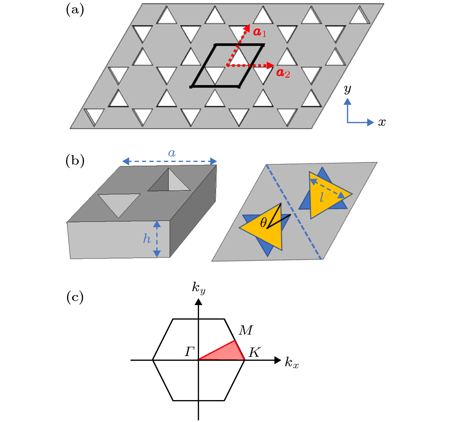 图 1 声子晶体板结构、元胞及其布里渊区示意图 (a) 具有三角形穿孔的声子晶体板结构; (b) 声子晶体板的元胞; (c) 晶格的第一布里渊区和不可约布里渊区(红色区域)
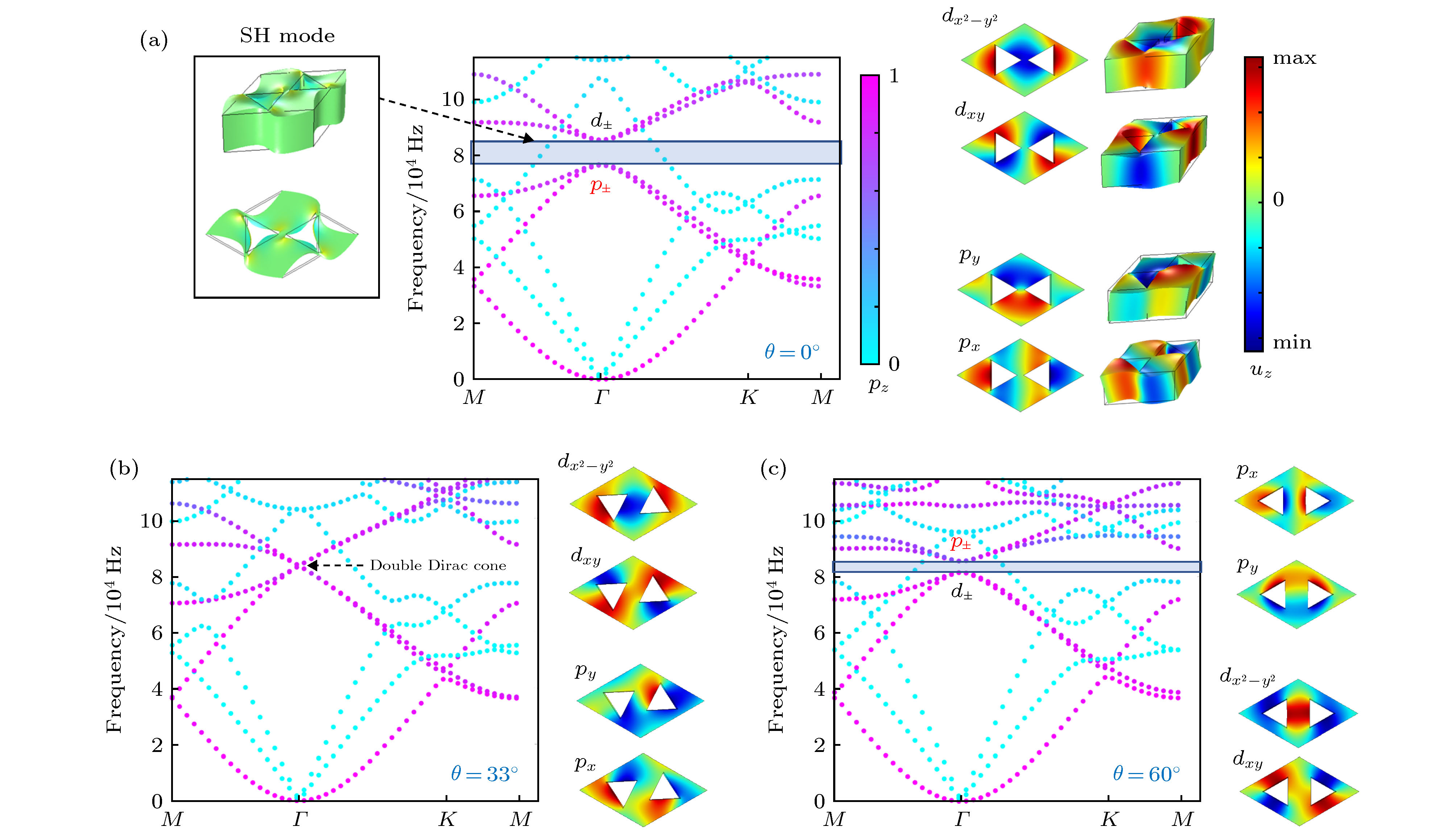 图 2 三角形穿孔声子晶体板在不同旋转角度下的能带结构与本征态z方向位移场分布 (a)


 图 3 晶格参数变化对布里渊区中心Γ点的偶极模态和四极模态能带特征频率的影响 (a) 三角形穿孔旋转角度θ的影响; (b) 三角形穿孔边长l的影响


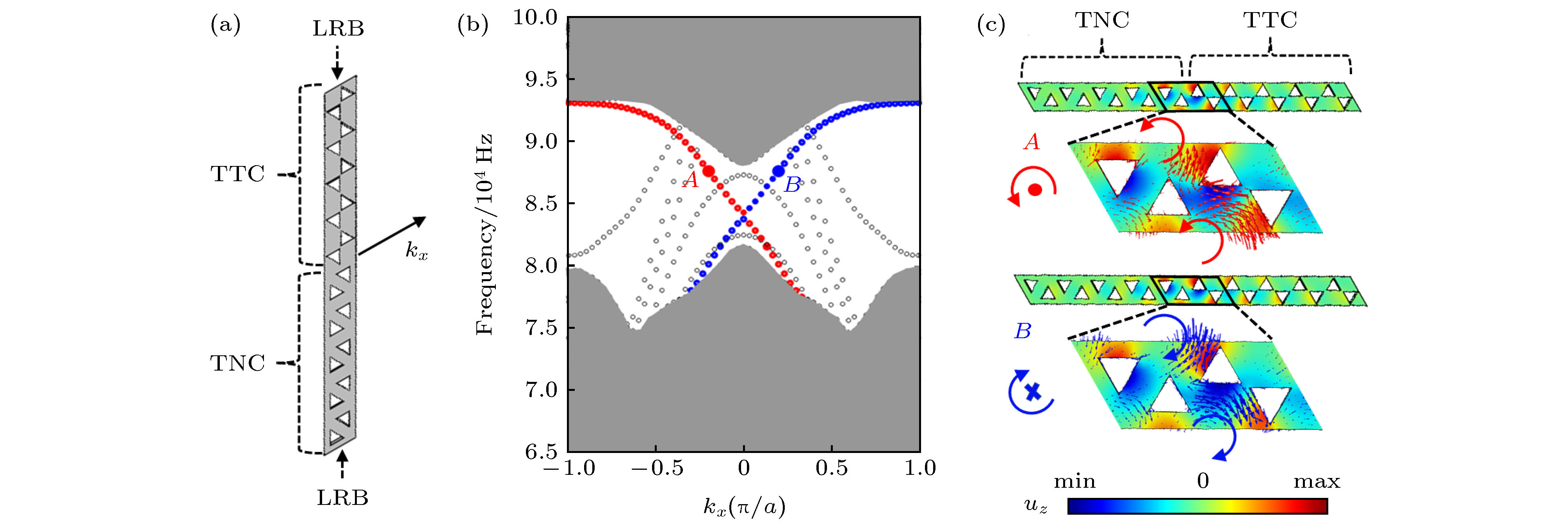 图 4 (a) 由5个TTCs与5个TNCs组成的超元胞; (b) 该超元胞的能带结构图, 其中红色和蓝色点代表边界态, A和B点为波矢


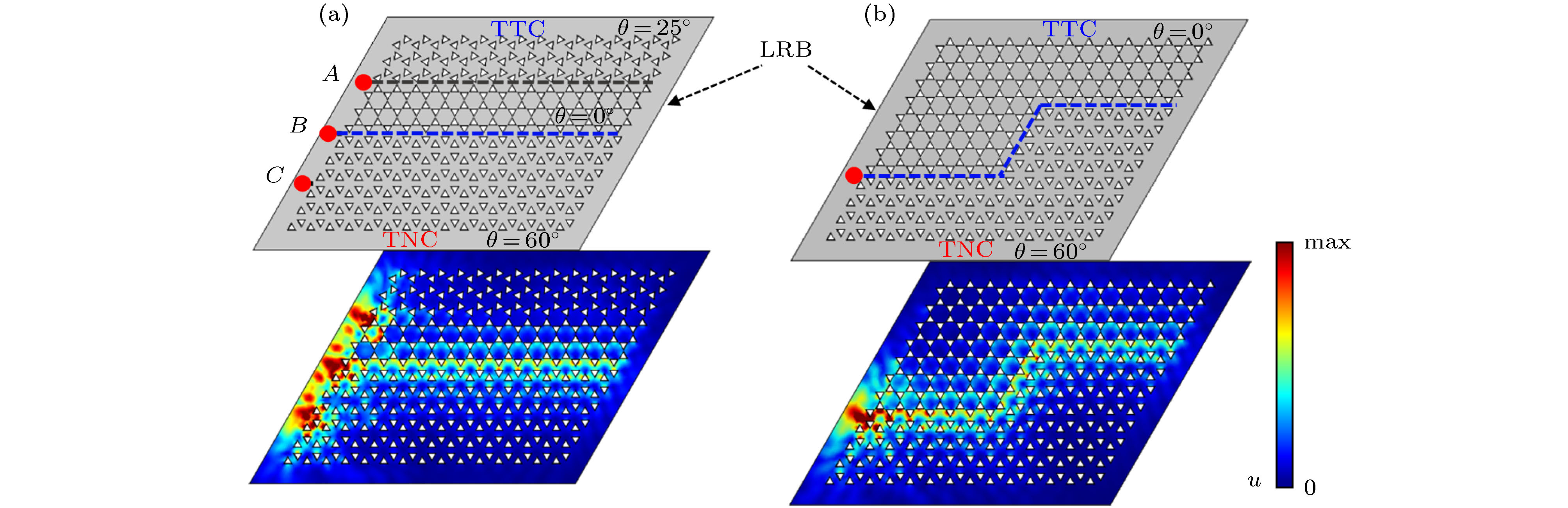 图 5 由TTCs和TNCs构成的不同通道的声子晶体板 (a) 黑色虚线表示


 图 6 由TTCs和TNCs构成的存在缺陷的声子晶体板 (a) “Z”字形通道中存在三角形穿孔缺失(红色点为激励位置), 下图为该声子晶体板在z方向振动激励下的位移场分布情况; (b) “Z”字形通道中存在乱序缺陷


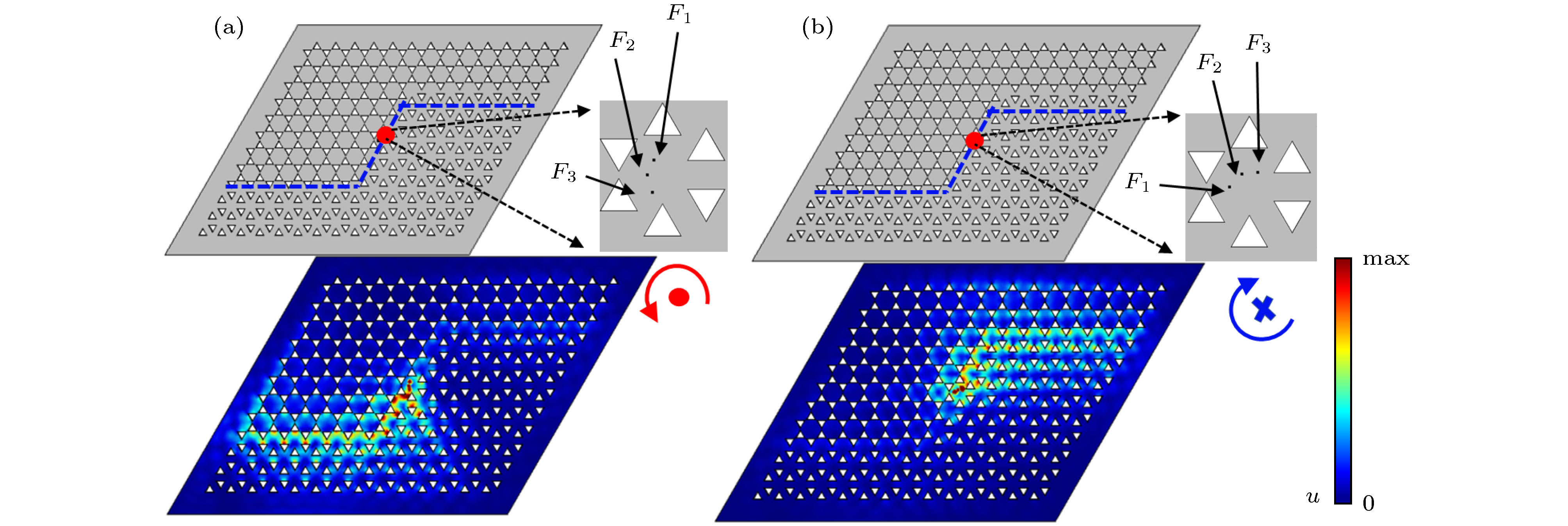 图 7 利用多点激励策略实现弹性波的单向传播(其对应的位移场分布情况清晰地说明了基于拓扑保护边界态下弹性波单向传播效果) (a)在多点激励下产生赝自旋+模态; (b) 在多点激励下产生赝自旋–模态
 图 8 基于拓扑保护边界态的多通道波导开关 (a) 声子晶体板上蓝色虚线为不同类型晶体构成的四个波导通道, 并在板左侧设置蓝色激励点, 其中蓝色或红色圆形箭头表示弹性波从激励点出发沿该通道传播时的赝自旋方向; (b) 激励点为左侧蓝点时的位移场分布, 放大图显示了边界态处的机械能量通量方向; (c) 在晶体板上侧设置红色激励点; (d) 激励点为上侧红点时的位移场分布


