1.College of Physics and Energy, Fujian Normal University, Fujian Provincial Key Laboratory of Quantum Manipulation and New Energy Materials, Fuzhou 350117, China 2.Fujian Provincial Collaborative Innovation Center for Optoelectronic Semiconductors and Efficient Devices, Xiamen 361005, China
Fund Project:Project supported by the National Natural Science Foundation of China (Grant No. 61574037) and the Natural Science Foundation of Fujian Province, China (Grant Nos. 2017J01553, 2016J01007).
Received Date:26 December 2018
Accepted Date:25 March 2019
Available Online:01 May 2019
Published Online:20 May 2019
Abstract:Magnetic nanorings can be high-density integrated because their stray field is low in vortex states. In this paper, the magnetic dynamic properties of the defective Fe nanorings are studied. For convenience, we assume the defect to be round in shape, whose coordinate is (0, Y). Based on the Monte Carlo method and fast Fourier transformation micromagnetism method, the magnetic properties of the defective Fe nanorings, such as hysteresis loops, spin configurations, remanence, etc., are studied. The simulation results indicate that the magnetization process of the system can be affected by the sizes and locations of the defects. When the defects are small, the system has a bistable state, which is similar to the system without defects. The transition state of the system increases as the defects are enlarged, and the bistable state will be no longer so visible. The system becomes open when the defects are big enough. Meanwhile, its hysteresis loop presents a rectangular shape which is similar to cluster’s or quantum dot’s. The remanence increases with the radius of defect increasing. These results are in accord with the magnetic properties of asymmetric magnetic nanoring. In order to explain the above results, the spin configurations of the system are shown. The spins of defective nanorings are divided into two parts, i.e., upper half part and lower half part, which are represented as blue and black spins respectively. When the system does not have any defects, the number of blue spins is equal to black spins’. Therefore the remanence is zero when the system is in a vortex state. It is found that the number of blue spins decreases as the radius of defect increases. This situation results in the total magnetic moment increasing, which leads the remanence to increase. However, the relationship between remanence and Y (the distance between center of nanoring and center of defect) is nonlinear. The remanence first increases and then decreases with Y increasing. The simulation results can be explained by changing the spin configuration. By analyzing the spins of the upper and lower part, the magnetic moment of the system is analyzed. It is found that the number of the spins and the local vortexes can affect the remanence significantly. The results show that the magnetic properties of Fe nanorings can be affected by the defect. Keywords:Monte Carlo simulation/ fast Fourier transformation micromagnetism method/ defective Fe nanoring/ magnetic properties
3.结果与讨论图2为R = 100 nm, r = 40 nm, Y = 30 nm, D分别为0—70 nm的纳米环的磁滞回线. 值得注意的是, 由于Y = 30 nm, 因此当D = 10 nm(图2(a))时, 系统并无缺陷, 即此时纳米环为对称体系, 其磁滞回线与对称铁磁纳米环磁滞回线一致, 存在典型的双稳态[18]. 从图2中还可以发现, 当D = 20—40 nm, 即D ≤ r时(如图2(b)-(d)), 系统的磁滞回线均呈现出较为明显的台阶, 说明此时系统虽然存在缺陷, 但依然保持着磁性纳米环系统的双稳态特征[16,18]; 随着D的增大, 系统的过渡态逐渐增多; 当D = 50—60 nm, 即D > r时(如图2(e)—(f)), 由于存在众多的过渡态, 系统的台阶不再明显, 即双稳态特征已逐渐模糊; 当D = 70 nm时, 系统由于缺陷太大而从上部断开, 此时系统不再是一个圆环状态, 磁滞回线的双稳态特征消失, 其形状接近矩形, 此时系统类似于原子团或量子点的磁化行为[24-26]. 从图2中可见, 随着D值的增加, 系统的剩磁也逐渐增大, 这一结论与不对称磁性纳米环的特征类似[18,19]. 图 2 不同D值的纳米环磁滞回线(Y = 30 nm, R = 100 nm, r = 40 nm) Figure2. Hysteresis loops of defective Fe nanorings with different D (Y = 30 nm, R = 100 nm, r = 40 nm).
为了研究系统剩磁与缺陷半径D的关系, 我们模拟了不同Y值条件下系统的剩磁随D值变化的曲线, 如图3所示. 从图3中可以发现, 对于无缺陷系统(Y = 30 nm, D = 0—10 nm), 系统的剩磁接近于零. 而当系统的D值增加时, 不同Y值的系统剩磁都随缺陷半径的增大而明显增大. 图 3 不同Y值条件下系统剩磁随D值的变化(R = 100 nm, r = 40 nm) Figure3. The relation between the remanence and D with different Y (R = 100 nm, r = 40 nm).
为了分析图3中剩磁变化的原因, 我们模拟了Y = 30 nm时, 零场状态下系统的组态, 如图4所示. 为了便于分析, 我们将系统自旋分为上下两个部分, 上半部分自旋用蓝色表示, 下半部分自旋用黑色表示. 从图4可以看出, 当外场为零时, 不同D值的系统均为“涡旋态”. 当D = 0—10 nm时(如图4(a)), 系统处于无缺陷状态, 这时自旋组态的上半部分原子个数与下半部分原子个数相同, 但自旋方向相反(蓝色部分偏向左侧, 黑色部分偏向右侧). 设蓝色部分合磁矩矢量为$\sum {{{{m}}_1}} $, 黑色部分合磁矩矢量为$\sum {{{{m}}_2}} $. 由于$\sum {{{{m}}_1}} $与$\sum {{{{m}}_2}} $的方向相反, 则系统合磁矩$\sum {{m}} = {\sum {{m}} _1} + {\sum {{m}} _1} \approx 0$, 因此系统磁化强度接近于零; 随着D值从20 nm逐渐增大至60 nm(如图4(b)—(f)), 缺陷面积逐渐增大, 系统蓝色部分原子个数逐渐减少(即$\sum {{{{m}}_1}} $减小), 而黑色部分原子个数不变($\sum {{{{m}}_2}} $基本不变), 因此$\sum {{m}} $增大, 导致系统剩磁增大; 当D = 70 nm时, 系统断开(如图4(g)), 不再构成一个完整的环, 此时由于缺陷面积很大, 蓝色部分原子数远小于黑色部分, 因此$\sum {{m}} $继续增加, 从而出现了图3中剩磁随D值的增大而增大的现象. 图 4 不同D值的铁纳米环零场下的自旋组态图(Y = 30 nm, R = 100 nm, r = 40 nm) Figure4. The spin configurations of Fe nanorings for different D with zero field (Y = 30 nm, R = 100 nm, r = 40 nm)
为了研究系统剩磁与Y值的关系, 我们模拟了D = 30 nm 时, 剩磁随Y值变化曲线, 如图5所示. 从图5中可以看出, 剩磁随着Y值的增加而明显的变化: 当Y为0—10 nm时, 系统剩磁保持不变; 当Y为20—90 nm时, 剩磁随Y的增加而增加, 并在Y = 90 nm时达到最大值; 当Y为90—140 nm时, 剩磁随Y的增加而减小. 图 5 剩磁随缺陷Y值变化曲线(D = 30 nm, R = 100 nm, r = 40 nm) Figure5. The relation between the remanence and Y (D = 30 nm, R = 100 nm, r = 40 nm).
为了解释Y值的增加导致剩磁先增大后减小的现象, 我们模拟了零场时与图5相对应的组态(如图6). 从图6中可以看到, 当Y为0—10 nm时, 系统处于无缺陷状态. 此时纳米环为“涡旋态”. 根据上述分析可知, 此时系统的磁化强度接近于0. 随着Y值增加, 缺陷开始上移(如图6(b)), 此时系统蓝色部分原子个数随着Y的增加而减少(当Y < 70 nm时), 即$\sum {{{{m}}_1}} $减小, 而$\sum {{{{m}}_2}} $几乎不变, 因此系统合磁矩$\sum {{m}} $增加, 从而导致系统剩磁增加. 图 6 不同Y值的铁纳米环的自旋组态图(D = 30 nm, R = 100 nm, r = 40 nm) Figure6. The spin configurations of Fe nanorings for different Y (D = 30 nm, R = 100 nm, r = 40 nm).
 图 1 缺陷铁纳米环模型


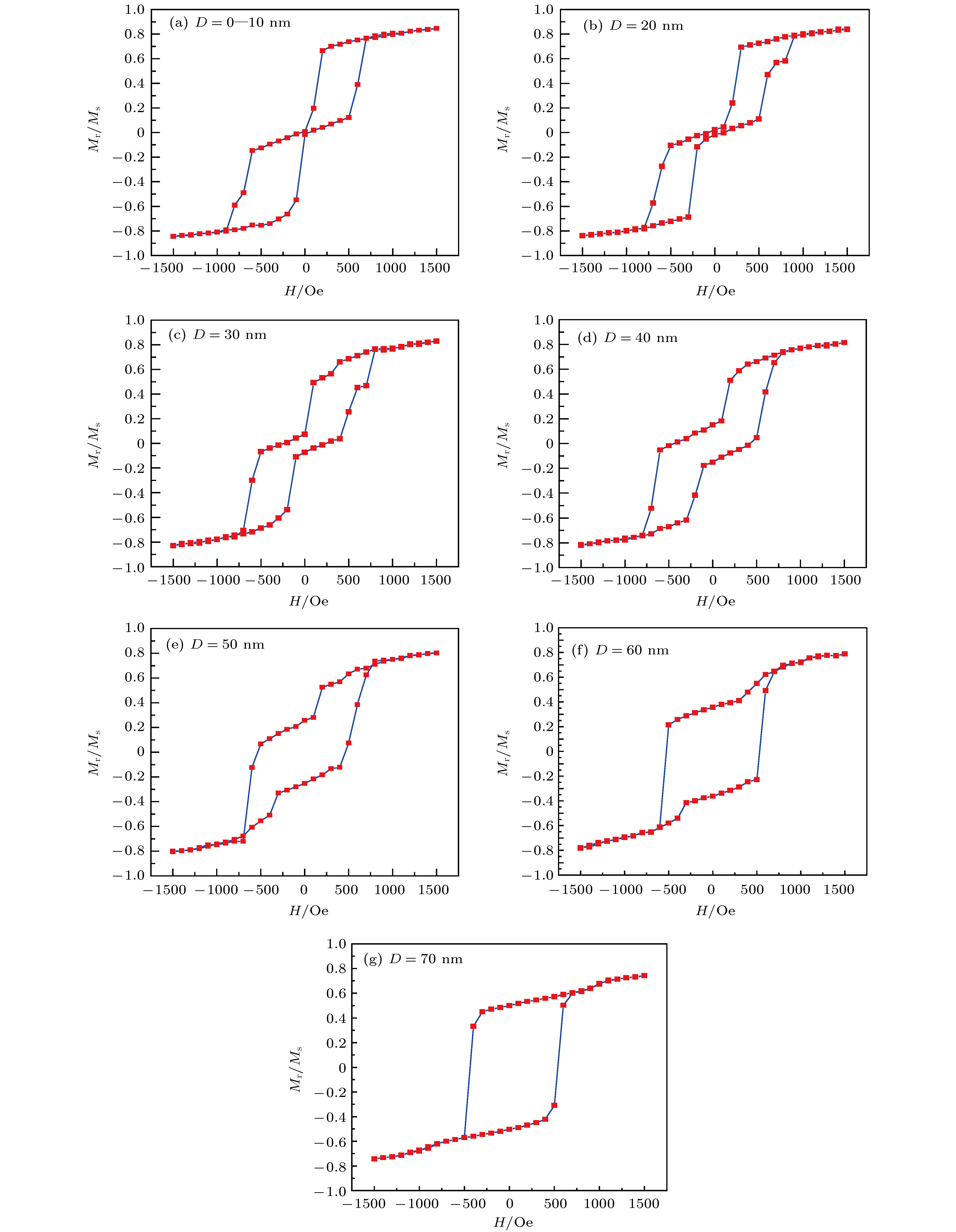 图 2 不同D值的纳米环磁滞回线(Y = 30 nm, R = 100 nm, r = 40 nm)
 图 3 不同Y值条件下系统剩磁随D值的变化(R = 100 nm, r = 40 nm)


 图 4 不同D值的铁纳米环零场下的自旋组态图(Y = 30 nm, R = 100 nm, r = 40 nm)
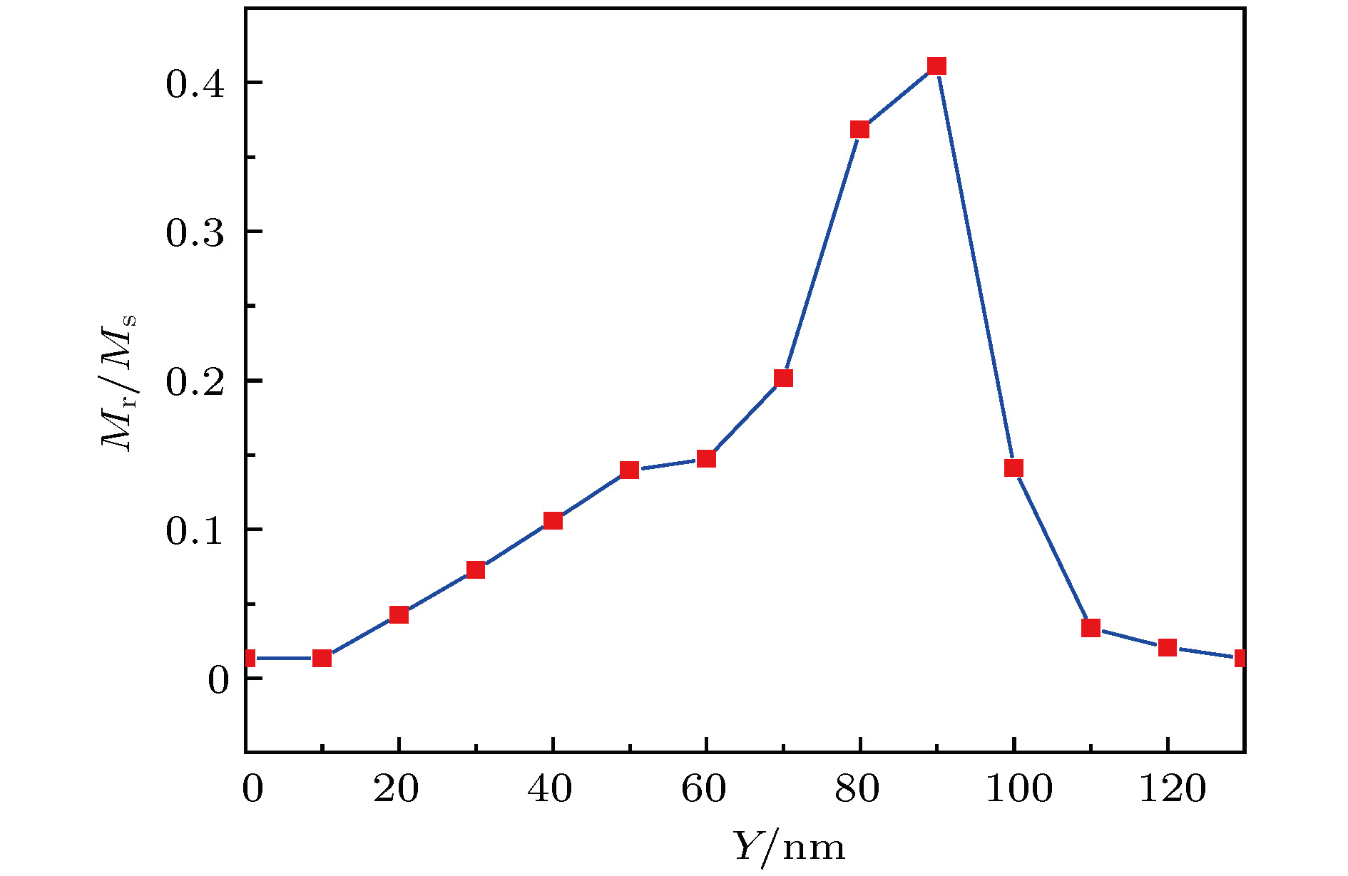 图 5 剩磁随缺陷Y值变化曲线(D = 30 nm, R = 100 nm, r = 40 nm)


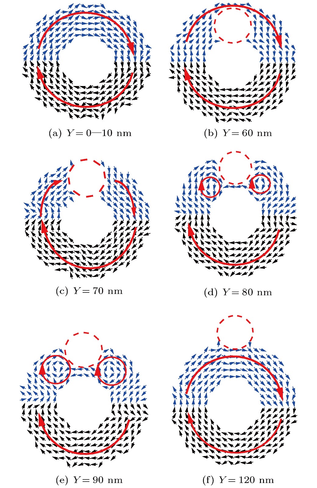 图 6 不同Y值的铁纳米环的自旋组态图(D = 30 nm, R = 100 nm, r = 40 nm)


