 ,2), 马鸿博, 张伟机械结构非线性振动与强度北京市重点实验室, 北京 100124
ENERGY HARVESTING ANALYSIS OF A PIEZOELECTRIC CANTILEVER BEAM WITH MAGNETS FOR FLOW-INDUCED VIBRATION 1)
Cao Dongxing,2), Ma Hongbo, Zhang WeiBeijing Key Laboratory of Nonlinear Vibrations and Strength of Mechanical Structures, Beijing 100124, China通讯作者: 曹东兴, 副教授, 主要研究方向: 动力学与控制. E-mail:caostar@bjut.edu.cn
收稿日期:2018-12-10接受日期:2019-01-31网络出版日期:2019-07-18
| 基金资助: |
Received:2018-12-10Accepted:2019-01-31Online:2019-07-18
作者简介 About authors

摘要
流致振动蕴含巨大的能量, 本文基于流致振动理论,设计了一种附加磁力激励的压电悬臂梁流致振动俘能器,并通过理论和实验研究其振动俘能特性.该俘能器由压电悬臂梁、圆柱绕流体和磁铁组成;首先基于Euler-Bernoulli梁理论,推导了流致振动附磁压电俘能器的能量函数,利用Hamilton原理建立了流致振动附磁压电俘能器的机电耦合方程;利用数值方法研究详细分析了流速、圆柱绕流体直径和长度、磁间距、磁极和外接电阻等系统参数对压电俘能器振动特性和输出电压的影响.分析结果表明, 该型压电俘能器的振动幅值在低流速条件下产生涡激振动,并产生最大的输出电压;磁力可以降低压电俘能器的共振频率并能够拓宽压电俘能器频带带宽,因此,附磁压电俘能器具有相比没有附磁的压电俘能器更适用于低速层流环境;实验结果与数值结果吻合较好,验证了附磁压电悬臂梁流致振动俘能器的理论分析的正确性.
关键词:
Abstract
Flow-induced vibration contains tremendous energy. Based on the theory of flow-induced vibration, a kind of flow-induced vibration energy harvester with additional magnetic excitation is designed, and its vibration energy harvesting characteristics are studied theoretically and experimentally. The harvester consists of a piezoelectric cantilever beam, a circular cylinder and magnets. Firstly, based on the Euler-Bernoulli beam theory, the energy functions of the magneto-piezoelectric energy harvester with fluid-induced vibration excitation are derived, and the electromechanical coupling equation is established by using the Hamilton principle. Then, the influence of the system parameters such as the flow velocity, the diameter and length of the circular cylinder, the magnetic parameters and the external resistance on the vibration characteristics and output voltage of the piezoelectric energy harvester. The results show that the vibration amplitude of the piezoelectric harvester produces vortex-induced vibration at low flow velocity and output the maximum voltage; the magnetic force can reduce the resonance frequency of the structure and broaden the bandwidth harvester. Thus, the magnetized piezoelectric harvester is more suitable for low-speed flow environment than the non-magnetized piezoelectric harvester. The experimental results agree well with the numerical results, which verifies the results of the theoretical analysis of the magneto-piezoelectric energy harvester.
Keywords:
PDF (3751KB)元数据多维度评价相关文章导出EndNote|Ris|Bibtex收藏本文
本文引用格式
曹东兴, 马鸿博, 张伟. 附磁压电悬臂梁流致振动俘能特性分析 1). 力学学报[J], 2019, 51(4): 1148-1155 DOI:10.6052/0459-1879-18-426
Cao Dongxing, Ma Hongbo, Zhang Wei.
引言
基于压电效应的振动能量采集技术与传统的光电转换和热能相比,具有能量密度高、响应快、寿命长、无污染、结构简单且易于集成到微电子系统等优点,成为低功耗新能源领域的研究热点[1-12].压电振动俘能器按照激励来源基本可分为基础振动激励和流致振动激励,如何拓宽俘能器工作频带, 提高俘能效率是目前该领域的研究重点.Erturk等[1]许多****提出了一种磁、弹耦合非线性压电振动俘能器结构,能够有效拓宽频带. Ooi等[2]通过分析多种不同几何形状的悬臂梁的应变分布,提出了用于振动能量采集的最优形状, 并实验验证了分析结果.我国****对此也进行了大量研究,Sun等[3]研究了双稳态压电俘能器的动力学,Zhou等[4-5]研究了三稳态压电振动俘能器,Zou等[6-7]研究了磁、弹耦合宽频俘能器,Lu等[8]基于snap-through动力学现象拓宽了俘能器频带,Liu等[9]研究了高斯色噪声激励的振动俘能器,Jiang等[10]和Cao等[11]利用内共振特性研究了非线性振动俘能器动力学特性.自然界和工程领域存在大量的流体环境,流致振动蕴含着巨大的能量[13-15]. 近年来,随着压电振动俘能技术的发展,流致振动的压电俘能器的研究受到广泛关注[16-19].Weinstein等[20]基于卡门涡激原理,设计了一种圆柱绕流风致振动压电俘能器用于满足监控系统或其他传感器的无线传感器供电.Zhang等[21]利用涡激振动与尾流诱发振动测试了附接有两个压电梁的刚性圆柱体,研究了不同流体激励引起的振动.Ding等[22]基于二维非定常Navier-Stokes方程,设计了不同绕流体形状压电俘能器,结果发现梯形压电俘能器在能量收集性能优于其他结构形状.Nicolaskofman等[23]考虑拖拽力和流体分离产生的压力设计了长条结构的压电俘能器并对其气动力模型进行了修正.Vicente-Ludlam等[24]设计了D型柱电磁压电俘能器并完成了多场耦合分析,研究发现最佳负载电阻和流速之间存在联系. Javed等[25]设计了三角形柱体压电俘能器,并研究了流速对压电俘能器的俘能特性影响.Pobering等[26]设计了一种PVDF水致振动压电俘能器.Xie等[27]设计了一种海浪压电俘能器,根据艾里线性波理论计算了压电俘能器的输出电荷和电压.Shan等[28]设计了一种使用新型压电复合材料MFC的压电俘能器,通过数值模拟研究了流速和绕流体直径对压电俘能器的俘能影响.Shan等[29]设计了一种利用偏心圆筒产生弯、扭耦合振动的低速水流压电俘能器,俘能效果是传统实心压电俘能器的1.99倍.Song等[30]提出一种复摆式涡激振动压电俘能器用于低速水流的能量收集,基于流、固、电耦合仿真分析和实验测试的方法研究了水流流速对复摆式压电俘能器振动和俘能特性的影响规律.
总结分析可知,现有流致振动压电俘能器的结构形式主要包括涡激振动式、驰振式和颤振式三种.本文基于圆柱绕流涡激振动理论提出一种带有磁力增强的流致振动压电俘能器.首先利用Euler-Bernoulli梁理论推导该结构的能量函数,利用Hamilton原理建立其机电耦合控制方程;进一步通过数值分析和实验研究了流场流速、绕流体参数、磁场参数和外接电阻对压电俘能器振动特性和输出电压的影响.
1 结构模型和基本假设
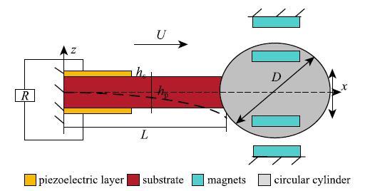
流致振动附磁压电俘能器结构如图1所示,主要包括压电悬臂梁和圆柱绕流体组成. 流场速度$U$,压电悬臂梁由压电层(PZT)铺设在金属基体层上而组成, 梁长$L$, 梁宽$b$,PZT压电层和基层的厚度分别为$h_{p}$和$h_{s}$,压电层长为$L_{p}$, 圆柱绕流体的直径$D$, 高度$l_{c}$.圆柱的磁极与固定磁铁的磁极相吸, 磁间距$d$, 外接电阻$R$.图1
 新窗口打开|下载原图ZIP|生成PPT
图1流致振动附磁压电俘能器结构示意图
Fig. 1Schematic diagram of PEHM
在推导流致振动附磁压电俘能器的机电耦合控制方程之前,进行以下假设:(1) 压电悬臂梁被认为是Euler-Bernoulli梁,既不考虑剪切变形;(2) 忽略粘合层的影响, 即压电层和基层理想的粘合,粘合层上的位移和力是连续的;(3) 压电层产生垂直方向的电场,并沿厚度方向均匀分布.
2 理论模型
2.1 分布参数机电耦合能量函数描述
考虑大变形应变、位移几何非线性关系[31]\begin{equation}\label{eq1} S_x =-z \cdot \left({v}" + \frac{1}{2}{v'}^2{v}"\right) (1) \end{equation}式中, $v(x,t)$表示梁上某一点相对运动基础在$z$轴的位移;$(^\prime)$表示对位移求偏导数, 即$(^\prime ) = \partial/\partial x$;$z$表示压电悬臂梁从中性轴开始的位置.各向同性的基层遵循胡克定律\begin{equation}\label{eq2} T_x = E_z S_x (2)\end{equation}式中, $T_x $, $S_x $和$E_s$分别为基层的轴向应力、轴向应变和弹性模量.
由于流致振动附磁压电俘能器系统作横向振动, 考虑压电材料的压电效应,压电层采用第二类压电方程, 其本构关系可写为[32]\begin{equation}\label{eq3} T_x = c_{xx}^{E} S_x-d_{zx}E_z (3)\end{equation}\begin{equation}\label{eq4} D_{z} = d_{zx} S_x + \varepsilon _{zz}^{S}E_z (4)\end{equation}式中, $T_x $和$S_x $是应力和应变, $c_{xx}^{E}$为恒定电场下的短路弹性刚度系数, $d_{zx} $为压电耦合系数, $E_z$是$z$方向的电场强度, $D_z $是$z$方向的电位移, $\varepsilon_{zz}^{S}$为恒定应变下的介电系数.
根据前述假设, 在串联方式下, 电场在压电片上的分布为\begin{equation}\label{eq5} E_z =-\frac{V_R \left( t \right)}{2h_{ p}} (5)\end{equation}式中, $V_R \left( t \right)$是压电片外接负载电阻$R$两端的电压.
本文采用Hamilton原理建立流致振动附磁压电俘能器的机电耦合控制方程. \begin{equation} \label{eq6} \int_{t_1 }^{t_2 } {\left[ {\delta (T-U_X ) + \delta W} \right]{d}t = 0} (6) \end{equation} 式中, $T$是系统的动能, $U_X $是系统的势能, $W$是系统的外力做功.
2.1.1 系统动能
流体中压电梁的振动不同于空气中的振动,流体对压电俘能器振动的影响不容忽视, 由于流体黏度, 压电梁在流体中振动时产生额外质量, 流体中的阻尼远大于空气阻尼, 也不可忽视, 流体对压电梁振动的影响主要体现在附加质量和阻尼的影响上[33]. 因此, 系统总动能$T$包括基层动能$T_{s}$,压电层动能$T_{p}$, 圆柱绕流体动能$T_{M}$和梁悬臂梁附加质量动能$T_{b}$.
$$\begin{align*} & T = T_{M} + T_{p} + T_{s} + T_{b} = \\ &\qquad \frac{1}{2}M \cdot \dot {v}\vert _{x = L} ^2 + \frac{1}{2}\int_{V_{p}} {\rho _{p} \dot {v}^2{d}V_{ p}} + \frac{1}{2}\int_{V_{s} } {\rho _{s} \dot {v}^2_ {d}V_{s}} +\\ &\qquad \frac{1}{2}M_{b} \int_0^L {\dot {v}^2} { d}x (7)\end{align*} $$
式中, $(\cdot )$代表$\partial/\partial t$, $M =\dfrac{\pi}{4}D^2l_{c} (\rho _{f} + \rho _{c} )$是圆柱绕流体的等效质量, $\rho _{c}$是圆柱绕流体密度, $V_{ s}$是悬臂梁基层体积, $V_{p}$是压电层体积, $M_{ b}$为悬臂梁附加质量. 根据流体力学理论, 单位长度梁的附加质量为 \begin{equation} \label{eq8} M_{b} = \frac{\pi}{4}\rho _{f} b^2\Gamma _{r} (8) \end{equation} 式中, $\rho _{f}$是流体密度.
2.1.2 系统内势能
压电俘能器的内势能为
$$U_{nei} = \frac{1}{2}\int_{V_{s}} {T_x S_x } {d}V_{s} + \frac{1}{2}\int_{V_{p}} {T_x S_x } {d}V_{ p}({9}) $$
将方程(2)和(3)代入方程(9), 压电俘能器的内势能可以表示为
$$ \begin{align*} & U_{nei} = \frac{1}{2}\int_{V_{s}} {E_{s} S_{x}^2 } {d}V_{s} + \frac{1}{2}\int_{V_{p}} {c_{xx}^{E} S_x^2 } {d}V_{p} -\\ &\qquad\frac{1}{2}\int_{V_{p}} {d_{zx} S_x } E_z {d}V_{ p} = U_{s} + U_{ps}-U_{pe}(10)\end{align*} $$
2.1.3 系统电势能
压电俘能器系统的电势能为
$$U_{pd} = \frac{1}{2}\int_{V_{p}} {D_z E_z } {d}V_{ p}(11) $$
将方程(4)代入方程(11), $U_{pe} $可以表示
$$ U_{pd} =-\frac{h_{s} d_{zx} V_R b}{4}\left. {\left( {{v}'_ + \frac{1}{6}{v}'^3} \right)} \right|_0^L + \frac{\varepsilon _{zz}^{S} bL_{p}}{4h_{ p}}V_R^2(12) $$
2.1.4 系统虚功
在本文模型中, 附磁压电俘能器在广义坐标上的虚功可表示为
$$\delta W = \delta W_{d} + \delta W_{fb} + \delta W_{fc} + \delta W_{F_{L}} + \delta W_R + \delta W_{F_{mag} }(13) $$
式中,各项依次为系统机械阻尼消耗的虚功$W_{d} $, 流体对梁附加阻尼消耗的虚功$W_{fb} $, 圆柱流体附加阻尼消耗的虚功$W_{fc} $, 圆柱涡街升力所做虚功$W_{F_{L}} $, 系统外接电阻消耗的虚功$W_R $, 磁力所做虚功$W_{F_{mag}}$.
涡街升力所做虚功为
$$\delta W_{F_{L}} = \int_0^{l_{c}} {F_{L} {d}x} \cdot \delta v\left( {L,t} \right)(14) $$
式中, $F_{L} = \dfrac{1}{2}C_{L}\rho _{f} DU^2\cos \left( {\dfrac{2\pi S_t U}{D}t} \right)$为圆柱涡街升力, $C_{L}$为升力系数, $D$是圆柱直径, $U$是水流流速, $S_t$是斯特劳尔数.
磁铁之间的几何关系如图1所示, 磁力可以表示为[34]
$$ \left. {{\begin{array}{l} F_{mag1} =-\dfrac{3\tau a_1 a_2 }{2\pi (d-v\left( {L,t} \right))^4}\\[2mm] F_{mag2} = \dfrac{3\tau a_1 a_2 }{2\pi (d + v\left( {L,t} \right))^4}\\ \end{array} }} \right\}(15) $$
式中, $\tau $是真空磁导率, $a_1$, $a_2$是磁偶极距, 当磁相吸时, $a_1 =-a_2 $;当磁极相斥时, $a_1 = a_2 $.
磁力所做虚功为
$$ \begin{align*} & \delta W_{F_{mag} } = F_{mag} \cdot \delta v\left( {L,t} \right)=\\ &\qquad F_{mag1} \cdot \delta v\left( {L,t} \right) + F_{ mag2} \cdot \delta v\left( {L,t} \right)=\\ &\qquad-k\frac{8}{d^5} \cdot v\left( {L,t} \right) \cdot \delta v\left( {L,t} \right)(16)\end{align*} $$
式中$k = \dfrac{3\tau a_1 a_2 }{2\pi}$.
2.2 压电俘能器动力学方程
把上述所有能量表达式代入Hamilton原理, 根据振动理论进行一阶离散,可得附磁压电俘能器动力学方程如下$$\begin{align*} & M_1 \ddot {r}\left( t \right) + c_1 \dot {r}\left( t \right) + k_1 r\left( t \right)-\alpha _1 r^2\left( t \right)V\left( t \right) + N_1^3 r^3\left( t \right) +\\ &\qquad N_1^5 r^5\left( t \right)-D_1 V_R \left( t \right) =\\ &\qquad \frac{1}{2}C_{L}\rho DU^2\cos \left( {\frac{2\pi S_t U}{D}t} \right)l_{c} \phi \left( L \right)(17)\\ & C_{P} \dot {V}_R \left( t \right) + \frac{V_R \left( t \right)}{R} + D_1 \dot {r}\left( t \right) + \alpha _1 r^2\left( t \right)\dot {r}\left( t \right) = 0(18)\end{align*} $$
引入以下无量纲变量
$$ x = \frac{r}{L}, \quad u = \frac{V_R }{V}, \quad \tau = \frac{t}{T}, \quad T = \frac{1}{\omega _1 }, \quad V_ = \frac{D_1 L}{C_P } $$
则方程(17)和(18)可以表示为
$$ \begin{align*} & \ddot {x} + 2\xi _1 \dot {x} + x + \kappa _1 x^3 + \kappa _2 x^5-\kappa _3 ux^2-\kappa _4 u = F\cos \left( {\varOmega \tau } \right) (19)\\ &\dot {u} + \gamma _1 u + \dot {x} + \gamma _2 x^2\dot {x} = 0(20)\end{align*} $$
3 数值分析
对于图1中的压电能量采集器, 其几何和材料参数列于表1中. 其中结构基层材料为铍青铜, 具有较大的弹性模量并能承受较大的变形, 压电层采用PZT-5H.Table 1
表1
表1附磁压电俘能器系统参数
Table 1
|

新窗口打开|下载CSV
针对流致振动横向附磁压电俘能器的机电耦合方程, 基于四阶Runge-Kutta 算法, 利用Matlab软件对压电俘能器系统进行数值模拟. 研究外接电阻、绕流体直径、绕流体长度、磁间距和磁极布置等对压电俘能器系统俘能特性的影响.
如图2所示, 具有不同磁间距布置的压电俘能器结构共振频率不同, 共振时所需水流流速不同. 当绕流体直径$D=24$ mm, 外接电阻$R=500$ k$\Omega $, 压电俘能器长$L=70$ mm时, 分析可知, 不同磁间距布置, 压电俘能器结构频率不同, 引入磁力, 可以改变压电俘能器的频率, 拓宽压电俘能器频带带宽;相吸磁极布置, 磁间距越大, 压电俘能器频率越高, 共振水流流速越大, 最大输出电压幅值越大. 当磁间距越大, 越趋近于无磁结构.
图2
 新窗口打开|下载原图ZIP|生成PPT
图2相吸磁极磁间距对输出电压的影响
Fig. 2The effect of the magnetic spacing on the output voltage at attractive magnetic pole
图2
 新窗口打开|下载原图ZIP|生成PPT
图2相吸磁极磁间距对输出电压的影响(续)
Fig. 2The effect of the magnetic spacing on the output voltage at attractive magnetic pole (continued)
如图3所示, 当绕流体直径$D=24$ mm, 外接电阻$R=500$ k$\Omega $, 压电俘能器长$L=70$ mm时, 分析可知, 相斥磁极布置, 随着磁间距越大,压电俘能器的固有频率越低, 共振所需水流流速越小;与相吸磁极布置结构相比, 相斥磁极布置, 由于存在磁场排斥力,使压电俘能器的固有频率增加;反之, 相吸磁极,可以有效降低压电俘能器的固有频率, 拓宽频带;相吸与相斥结构相比,相吸结构可以降低结构的频率, 拓宽频带,提高压电俘能器的能量采集相率.
图3
 新窗口打开|下载原图ZIP|生成PPT
图3相斥磁极磁间距对输出电压的影响
Fig. 3The effect of the magnetic spacing on the output voltage at repulsive magnetic pole
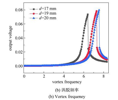
不同绕流体直径布置, 压电俘能器结构共振流速不同. 如图4所示,在磁间距$d=20$ mm, 外接电阻$R=500$ k$\Omega $, 压电俘能器长$L=70$mm时, 分析可知, 绕流体直径越大,压电俘能器共振流速越大;绕流体直径越大,压电俘能器的最大输出电压也越大;绕流体直径对俘能器的共振流速和输出电压都有影响.
图4
 新窗口打开|下载原图ZIP|生成PPT
图4绕流体直径对输出电压的影响
Fig. 4The effect of the diameter of the cylinder on the output voltage
不同绕流体长度布置, 压电俘能器结构输出电压不同. 如图5所示,在磁间距$d=20$ mm, 外接电阻$R=500$ k$\Omega $, 绕流体直径$D=24$ mm时,绕流体长度越长, 涡街升力越大, 阻尼力也越大,曲线呈现向右弯曲的性质;绕流体长度越长, 输出电压幅值越大,频率带宽越大;流体长度越长, 水流流速范围越大.
图5
 新窗口打开|下载原图ZIP|生成PPT
图5绕流体长度对输出电压的影响
Fig. 5The effect of the length of the cylinder on the output voltage
在水流流速分别为0.28 m/s, 0.37 m/s, 0.47 m/s, 磁间距$d=25$ mm,压电俘能器长$L=70$ mm, 绕流体直径$D=24$ mm时,压电俘能器输出电压与输出功率随电阻变化关系如图9. 分析可知,随着外接电阻的增大, 压电俘能器的输出电压也在增大, 趋于稳定;压电俘能器的输出功率随着外接电阻的增大,先增大后减小;在流速为0.281 m/s, 压电俘能器最大输出功率为0.024$\mu$W, 最优电阻为140 k$\Omega $.
图6
 新窗口打开|下载原图ZIP|生成PPT
图6电阻对输出电压和输出功率的影响
Fig. 6The effect of resistance on output voltage and output power
4 实验研究
根据压电俘能器结构参数设计并制作实验平台,搭建的压电俘能器实验平台如图7所示. 实验平台采用水循环系统,主要有水槽, 进水管, 出水管, 水泵组成. 实验中, 水流深度保持恒定,即水流横截面积保持不变, 通过流量控制水流流速.实验输出电压通过示波器显示.图7
 新窗口打开|下载原图ZIP|生成PPT
图7实验平台实物图
Fig. 7Experimental platform diagram
如图8所示, 压电俘能器长$L=70$ mm, 绕流体直径$D=24$ mm,相吸磁间距$d=30$mm与无磁结构得输出电压随时间变化曲线;研究发现:相同流速下,横向附磁俘能器输出电压大于无磁结构.
图8
 新窗口打开|下载原图ZIP|生成PPT
图8输出电压随时间变化曲线
Fig. 8Output voltage versus time curve
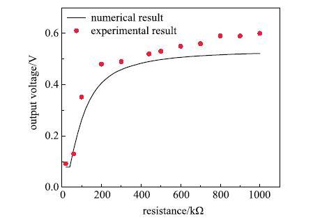
由图9可见, 当流速为0.280 m/s时,压电俘能器的输出电压随着外接电阻的增大而增大;实验结果与数值结果相对比,结果吻合较好, 验证了流致振动附磁压电俘能器的力学建模的正确性.
图9
 新窗口打开|下载原图ZIP|生成PPT
图9水流流速为0.280 m/s压电俘能器输出电压随电阻变化曲线
Fig. 9Output voltage of piezoelectric energy harvester with resistance curve at flow rate is 0.280 m/s
5 结论
本文提出了一种新型流致振动附磁压电能量采集器. 首先,通过Hamilton原理推导俘能器机电耦合方程,采用数值分析方法和实验方法研究各种系统参数(流速、绕流体参数、磁场参数和外接电阻)对流致振动附磁压电俘能器输出电压与输出功率的影响.得出如下结论:(1) 该系统在低速流体激励下具有良好的俘能效率.压电俘能器在涡激共振时振动幅值最大, 输出电压最大,压电俘能器的输出功率受电阻和流速两者的综合影响.
(2) 引入磁力, 可以降低压电俘能器的频率,拓宽压电俘能器频带带宽;相吸磁极布置, 磁间距越大,压电俘能器频率越高, 共振水流流速越大, 最大输出电压幅值越大.
(3) 绕流体直径对俘能器的共振流速和输出电压都有影响.绕流体直径越大, 压电俘能器共振流速越大, 俘能器的输出电压也越大.
(4) 随着外接电阻的增大, 压电俘能器的输出电压也在增大,趋于稳定;压电俘能器的输出功率随着外接电阻的增大, 先增大后减小.
附录
$$\begin{align*}& M_i = \int_0^L {\rho _{S} A_{S} \phi \left( x\right)^2{d}x} + \int_0^{L_p }{2\rho _{P} A_{P} \phi \left( x \right)^2{d}x}+ \\&\qquad \int_0^L {\frac{\pi }{4}\rho _{f} b^2\varGamma_{r} \phi \left( x \right)^2{d}x} + M\phi \left( L\right)^2\\& c_i = \int_0^L {c\phi \left( x \right)^2{d}x} + \int_0^L{\rho _{f} \frac{\pi}{4}b^2\omega ^2\varGamma _i \phi \left(x \right)^2{d}x} + c_{fc} l_{c} \phi \left( L\right)^2\\& k_i = \frac{E_{S} I_{S} }{2}\int_0^L {2{\phi }"\left( x\right)^2{d}x} + E_{P} I_{P} \int_0^{L_p } {2{\phi}"\left( x \right)^2{d}x} + k\frac{8}{d^5}\phi \left( L\right)^2\\&\alpha _i = \frac{\left( {h_1 + h_0 } \right)bd_{zx} }{2}{\phi}'\left( L \right)^3\\& N_i^3 = 2E_{S} I_{S}\int_0^L {{\phi }"\left( x\right)^2{\phi }'\left( x \right)^2{d}x} + 4E_{P} I_{P} \int_0^{L_{p}} {{\phi }"\left( x \right)^2{\phi}'\left( x \right)^2{d}x}\\& N_i^5 = \frac{3E_{S} I_{S}}{4}\int_0^L {{\phi }"\left(x \right)^2{\phi }'\left( x \right)^4{d}x} + \frac{3}{2}E_{P} I_{P} \int_0^{L_{p}} {{\phi }"\left( x \right)^2{\phi}'\left( x \right)^4{d}x}\\& D_i = \frac{\left( {h_1 + h_0 } \right)bd_{zx} }{2}{\phi}'\left( L \right)\\&\xi _1 = \frac{c_i }{2M_i \omega _1 }\\&\kappa _1 = \frac{N_3 L^2}{M_1 \omega _1^2 },\kappa _2 =\frac{N_5 L^2}{M_1 \omega _1^2 },\kappa _3 = \frac{\alpha D_1L^2}{C_{P} \omega _1^2 M_1 },\kappa _4 = \frac{D_1 ^2}{C_{P} \omega _1^2 M_1 }\\&F = \frac{C_{L}\rho _{f} DU^2l_{c} \phi \left( L\right)}{2M_1 L\omega _1^2 },\varOmega = \frac{2\pi S_tU}{D\omega _1 }\\&\gamma _1 = \frac{1}{C_{P} R\omega _1 }, \quad \gamma _2 =\frac{\alpha L^2}{D_1 }\end{align*}$$参考文献 原文顺序
文献年度倒序
文中引用次数倒序
被引期刊影响因子
DOIURL [本文引用: 2]
DOIURL [本文引用: 1]
DOIURL [本文引用: 1]
DOIURL [本文引用: 1]
DOIURL [本文引用: 1]
DOIURL [本文引用: 1]
DOIURL [本文引用: 1]
[本文引用: 1]
[本文引用: 1]
DOIURL [本文引用: 1]
DOIURL [本文引用: 1]
DOI [本文引用: 1]
DOIURL [本文引用: 1]
DOIURL
DOIURL [本文引用: 1]
[本文引用: 1]
[本文引用: 1]
DOIURL
[本文引用: 1]
[本文引用: 1]
[本文引用: 1]
[本文引用: 1]
DOIURL [本文引用: 1]
DOIURL [本文引用: 1]
[本文引用: 1]
[本文引用: 1]
//
[本文引用: 1]
DOIURL [本文引用: 1]
DOIURL [本文引用: 1]
DOIURL [本文引用: 1]
[本文引用: 1]
[本文引用: 1]
DOIURL [本文引用: 1]
[本文引用: 1]
[本文引用: 1]
DOIURL [本文引用: 1]
