
A REVIEW ON THE DEFORMATION AND FAILURE OF SEALS IN OILFIELD1)
WangZhengjin, WangTiejun��ͼ�����:TE25
���ױ�ʶ��:A
ͨѶ����:
�ո�����:2019-03-19
�����������:2019-05-18
��Ȩ����:2019��ѧѧ���ڿ��� ����
��������:
չ��
ժҪ
�ؼ��ʣ�
Abstract
Keywords��
-->0
PDF (45847KB)Ԫ������ά��������������ղ�����
�������ø�ʽ����EndNoteRisBibtex�ղر���-->
�� ��
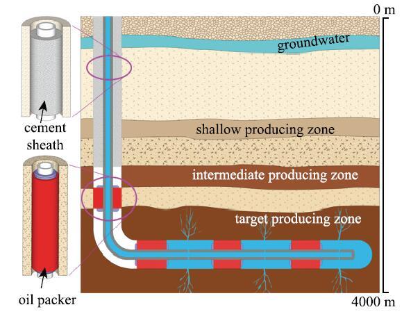
��Դ��������������.��������Դ�鱨�����,2040��������Դ������2012���$5.79\times10^{17}$ kJ������$8.60\times 10^{17}$ kJ,����Լ48%.��������Դ�ͺ��ܿ�������,����ʱʯ�ͺ���Ȼ����Ȼ����Ҫ��Դ[1].����ٽ���������ҵ����ؼ����ķ�չ,��ˮƽ�꾮����[2]��ˮ��ѹ�Ѽ���[3-7]�������ܷ���Ϻ���[8-9]�Ŀ�����.����������һ�����ӵ�ϵͳ����.����ʽ����ǰ,��Ҫͨ��̽�⡢�꾮���̾����꾮����ҵ,�����������ɼ��Ĺ�������.������������������������,�����ܷ���ȷ����ȫ������Ч�ʵ���Ҫ����[9-10].���������ܷ�Ԫ����Ҫ����ˮ��ߵ�����������,��ͼ1��ʾ.���ڵͳɱ��������ʡ��̻����ص�,ˮ�౻�㷺�����ܷ⾮�ں��ܼ�Ļ��οռ�.ˮ�����Ҫ�������ṩ��λ���(����ֹ��ͬ�ز��λ�����廥����ͨ)��֧���ܡ���ֹ�ܸ�ʴ��.����ʽ�ߵ���������һ����Խ��µ��ܷ��,���гɱ��͡�������㡢�Զ��ܷ⡢���ѹ������ŵ�,������ˮ��ѹ�ѡ������̾���������졢��ˮ����ɰ����ҵ,������������̾�[11].�ܷ�ṹʧЧ�ή������Ч��,����������صĻ�����Ⱦ�������Ʋ���ʧ.�ںܳ�һ��ʱ����,�������ܷ���Ҫ�ɾ�������,ȱ��ϵͳ�������о�.��������������ڵ���������Ƚ�dz,���ʻ����Ƚϼ�,���ǵ���Ҫ�������������߹̾�Ч�ʵȷ���,û�й���ع�ע�ܷ�Ԫ������ѧ���ܡ�����������.Ȼ��,���ſ���ʱ������,dz��������ԴԽ��Խ��[12-13],���Dz��ò�����ҳ�ҡ���ͼ��صķdz���������Դ����[14].
 ��ʾԭͼ|����ԭͼZIP|����PPT
ͼ1�������ܷ�ʾ��ͼ
-->Fig. 1Schematic of sealing in oil and gas wells
-->
������,�ڸ��¡���ѹ����ˮ�ȼ��˻��������е�������������������[15-16],����ܷ�Ԫ���Ŀɿ�������˸���Ҫ��.����,������̼������洢������Ӧ�öԵ�������ܷ�Ч������������Ҳ����˸��Ͽ�Ҫ��[17].ʵ������,Ŀǰ���ܷ���ҵ�����ṩ����ķ��Ч��,��ʹ��ʼ�ܷ�����,������������ҵ���Կ��ܷ���й©.����,2000---2012���������ݿ���������������6.2%�ķdz�����������1.0% �ij�����������������й©[18].ˮ��ѹ�ѷ�����ҳ����ʹdz�����ˮ�еļ��麬����������[19]. ����Ҫ����,�������ܷ�ʧЧ�����Բ���.���,ϵͳ�����о��������ܷ�Ԫ����ʧЧ����,�����������ܷ�İ�ȫ���������ܷ���ϵ�ѡ���ܷ���������ƵȾ�����Ҫ����.
���Ľ����������ܷ�ṹʧЧ��Ϊ�Ĺ������о���չ,���ȼ�Ҫ���ܹ̾�ˮ��е�Ӧ����ʧЧģʽ��ʧЧ�о�, Ȼ���ص��������ʽ�ߵ�������������Խ��µ��ܷ�ṹ�����͡����Ρ����ѡ�����й©����Ӧ�õ�.
1 �̾�ˮ��ܷ�
�̾���ҵ��ʼ��1903��[10].��������̽��һ����Ⱥ�,������,�����ܺ;���֮��ע��ˮ�ཬ,��һ���̳�Ϊ�̾�.��ˮ�ཬ�̻���,ˮ������Լ����ڽ�����һ��,��ֹˮ�㡢�Ͳ������Ļ�����ͨ,�Ӷ���λ���������.������������ȵ�����,�꾮�����п�����Ҫ��ι̾�.����������ķ�չ,�̾������������Խ���,��Ҫ����ˮ��Ʒ�ֵķḻ���̾����ߵĸ������̾���ҵ���Զ����;�ȷ���Ƶ�.�̾�ˮ������������ɣ�����ˮ�����Ӽ�.���պ��ˮ����Ҫ�������ֳɷ֣���������($3\mbox{CaO} \cdot\mbox{SiO}_2 )$���������($2\mbox{CaO} \cdot \mbox{SiO}_2)$����������($3\mbox{CaO} \cdot \mbox{Al}_2 \mbox{O}{}_3)$���������ĸ�($4\mbox{CaO} \cdot \mbox{Al}_2 \mbox{O}_3 \cdot\mbox{Fe}_2 \mbox{O}_3 )$.����ˮ���ʱ,��Щ�ɷֺ�ˮ�������ӵ������ͻ�ѧ��Ӧ.�տ�ʼ��Ӧ���ʽϵ�,ˮ�ཬ����һ��ʱ���ڱ���������,�̾���ҵ��������һʱ�䴰�������.֮��Ӧ����,�������ɴ���ˮ�Ϲ��������(C-S-Hgel),ˮ�ཬ�̻�,ǿ��������.�̻����ˮ��ɷ���Ҫ��ˮ�Ϲ���ƺ�������ʯ[10].
�ɻ���ˮ���γɵ�ˮ�ཬ��Ӧ�÷�Χ�dz�����.Ϊ�����㲻ͬ��������Ⱥ͵ز����Ե�Ҫ��,��Ҫ��ˮ����������Ӽ�,��Ҫ�д�����������������ʧˮ�������ݼ��������ܼ�����ɢ�������������ؼ���.��Ӽ�������ˮ����������5%,�����;�ˮ�����������Ҫ��Ӱ��,�����ܸı�ˮ�ཬ������ѧ���ԡ��̻�ʱ��ȶ���������ȷ���̾��ɹ���,����Ӱ��ˮ��ij�����ѧ����,�絯��ģ�������ɱȡ�������ѹǿ�ȵ�.��Щ������ˮ��ķ��������ʹ����������ҪӰ��[20-21].
1.1 ˮ��̻������е�Ӧ���ݻ�
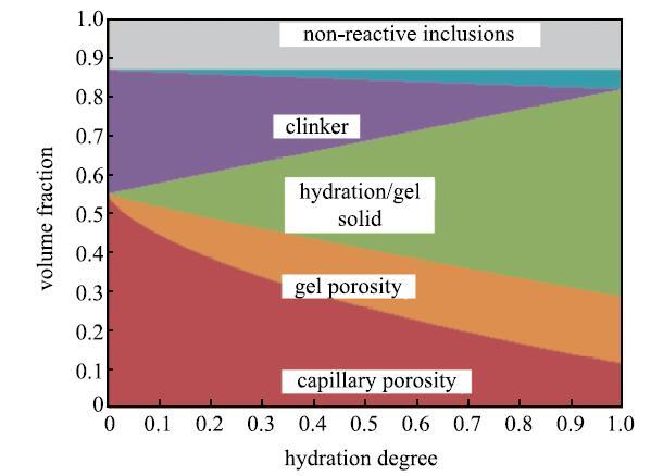
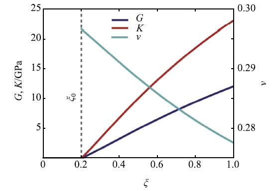
�̾�ˮ���ܵ��ܺ;��ڵ�Լ��,�ڹ̻������к̻�֮���ڸ��ӵ�Ӧ��״.��ˮ��е�Ӧ������ijһ�ٽ�ֵʱ,ˮ����ܷ����ƻ�,ʧȥ��λ�������,������ɴ������.���,����ˮ��е�Ӧ�������ݻ�,��Ԥ����Ԥ��ˮ���ʧЧ����Ҫ����.�����Ҫ����ˮ��ڹ̻������е�Ӧ���ݻ�.ˮ��̻���һ�����ӵĻ�ѧ--��ѧ����.�о�����[22-24],���Ź̻��̶ȵ�����,ˮ����������,���ɵ�ˮ�Ϲ����������������ʯ������(ͼ2),�����ϳ���,����ճ����һ���γɽ��ܵ���ά��ṹ.ˮ�ཬ�Ӳ���ѹ��������ת��Ϊ��ѹ�������,�䵯��ģ��($G$��$K)$���Ź̻��̶ȵ����Ӷ���������,�����ɱ�($\nu $)����(ͼ3).ˮ����Ӧ�����������ͨ��С�ڷ�Ӧ������,����ˮ���ڹ̻������в����������[22-23].�����ܺ;��ڵ�Լ��,ˮ�������������������Ӧ��,�����Ź̻��̶����Ӷ��仯(ͼ4).
 ��ʾԭͼ|����ԭͼZIP|����PPT
ͼ2ˮ��̻������и�������������̻��̶ȵı仯[
-->Fig. 2The relation between the volume fractions in hydrating cement and the degree of hydration[
-->
 ��ʾԭͼ|����ԭͼZIP|����PPT
ͼ3ˮ��̻������е���ѧ������̻��̶�($\xi )$���ݻ�[
-->Fig. 3The evolution of mechanical properties with the degree of hydration[
-->
 ��ʾԭͼ|����ԭͼZIP|����PPT
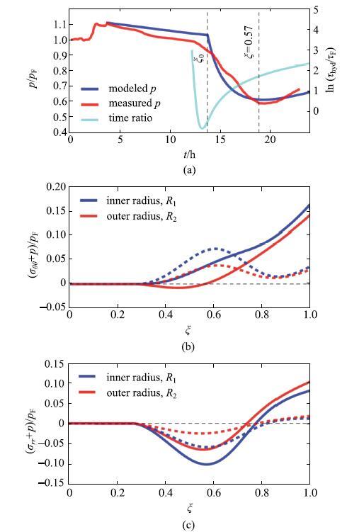
ͼ4ˮ��е� (a) ��϶ѹ��,(b) ��Ч����Ӧ���� (c) ��Ч����Ӧ����̻��̶ȵı仯. ʵ�߱�ʾӲ�Ҳ�(40 GPa);���߱�ʾ���Ҳ� (5 GPa) [
-->Fig. 4(a) The pore pressure, (b) effective hoop stress and (c) effective radial stress are plotted as functions of the degree of hydration. The solid lines are for stiff formation (40 GPa); dashed lines are for soft formation (5 GPa)[
-->
�����ģ���ܺܺõ�����ˮ�����ѧ����[24-26],Ulm��[27-29]���ö�߶Ⱦ��Ȼ�����Ԥ����ˮ�����ѧ������̻��̶ȵı仯��ϵ.�ڴ˻��������ö����ģ���Ƶ�����ˮ��еĿ�϶ѹ���͵�ЧӦ���ڹ̻������е��ݻ�����$^{[22\mbox{-}23,30]}$.�ڴﵽ�ٽ�̻��̶�֮ǰ,ˮ�ཬ���ȱ仯��С,�в��߱�ǿ��,���϶ѹ����������(ͼ4(a)),��ЧӦ��Ϊ��(ͼ4(b)��ͼ4(c)).�������ٽ�̻��̶Ⱥ�,ˮ����Ӧ�����������,��϶ѹ���ȼ��ٽ���,Ȼ����ƽ�Ȳ��ڹ̻����ǰ���ָ�.��϶ѹ���ı仯������Ҫ��ˮ����Ӧ���ʵ�Ӱ��.
��ͼ4(b)�ɼ�,�Ҳ�ĵ���ģ����ˮ��еĵ�Ч����Ӧ��Ӱ��ϴ�.�������ֲ�ͬģ�����Ҳ�,��϶ѹ���Ľ���ʹ��ˮ�/�ܽ��洦($R_{1})$�ĵ�Ч����Ӧ����������״̬.����Ӳ�Ҳ�,ˮ����Ҳ���洦($R_{2})$�ĵ�Ч����Ӧ�����ݽ���ѹ��״̬,Ȼ���Ϊ����״̬;���������Ҳ�,$R_{2}$���ĵ�Ч����Ӧ��һֱ��������״̬.�̻�������,Ӳ�Ҳ��Ӧ��ˮ���Ч����Ӧ��ҪԶ�������Ҳ����,��ˮ��ھ����ĵ�Ч����Ӧ��һֱ�����⾶���ĵ�Ч����Ӧ��.���,ˮ����ܽ��洦������������������.
ˮ��еĵ�Ч����Ӧ���Կ�϶ѹ���ı仯�dz�����.���ſ�϶ѹ���Ľ���,��Ч����Ӧ������ѹ��״̬.����϶ѹ��������Сֵʱ,��Ч����ѹӦ���ﵽ���.���,��϶ѹ����������,ˮ��еĵ�Ч����ѹ����С,�����ձ�Ϊ��Ӧ��.������Ϊ��ˮ����Ӧ����ˮ�û���㹻��ǿ��,��ЧӦ����Ҫ�ܿ�϶ѹ���仯��Ӱ��.�ڹ̻�����,ˮ�ǿ��������,ˮ��е�Ӧ��״̬��Ҫ�ܿ���ˮ�������������ܼ��Ҳ��Լ��ǿ��.ͬ��,��Ч����Ӧ����СҲǿ���������Ҳ�ĵ���ģ��.���̻���ɺ�,ˮ��еĵ�ЧӦ�����ٱ仯,����"����"״̬,ͨ������Ϊ��ʼӦ��.���ˮ�������������,��ʹû��ʩ���κ���ҵѹ��,ˮ�Ҳ������Ϊ��ʼӦ�����߶��ƻ�$^{[22\mbox{-}23,30\mbox{-}31]}$.
1.2 ������ҵ��ˮ��е�Ӧ��
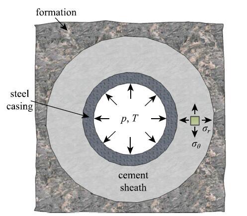
��ǰ����,ˮ���ڹ̻������л������ʼӦ��.�ں���������ҵ��,��ѹ�����¶ȵı仯���������µ�Ӧ��.����,��Ӧ������������ѹ����Ҳ��Ӱ��ˮ���Ӧ��״̬.���,Ҫ��ȷԤ��ͷ����̾�ˮ���Ӧ���Ƿdz����Ӻ����ѵ�.����,���ߵ���������,����������ɵ�Ӧ���������Ե���.���,�����ض�����,�����ҳ���ҪӰ������,�ٵ��ӵõ�����Ӧ��.�����������Ҫ���������أ���ѹ�����¶ȱ仯�����Ӧ��[32].����״̬��,�ܡ�ˮ����Ҳ���Լ�Ϊ����ͬ��Բ��(ͼ5),����ɵ����Ǿ��ȸ���ͬ�Բ���.���ڵ�ѹ��������Ϊ���»�����������ҵ���仯,�������ˮ���Ӧ��״̬�ı仯.ͨ�������,�ɺ�������ѹ���澮��ı仯,���ɽ������Ϊƽ��Ӧ������,�ɵ�����ѧ�еľ�����÷�������.
 ��ʾԭͼ|����ԭͼZIP|����PPT
ͼ5�������ĺ����ʾ��ͼ[
-->Fig. 5The cross-section of a well[
-->
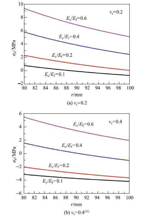
�̻�ˮ��Ŀ���ǿ��Զ�����俹ѹǿ��,���ˮ�����Ӧ��������.������ѹ������ʱ,ˮ��еľ���Ӧ��ʼ��ΪѹӦ��.����Ӧ���ķֲ���ͼ6��ʾ[32],��ˮ����ܽ��洦���,��ˮ�/�Ҳ���洦����.���,��ˮ����ܽ��洦������������������.�������ˮ�����Ҳ�ģ����($E_{\rm c}/E_{\rm f})$,ˮ��еĻ�����Ӧ����֮����,���п��ܴ�����Ϊѹ.ͬʱˮ��ɱȵ����Ҳ����Ч������Ӧ��.����ѹ������ʱ,������Ӧ�����С������ΪѹӦ��,������Ӧ�����ܱ�Ϊ��Ӧ��.��ʱ,ˮ����ܼ��Ҳ�Ľ��������Ϊ��Ӧ����ʧȥճ��,�γ���϶.
 ��ʾԭͼ|����ԭͼZIP|����PPT
ͼ6ˮ�������ѹ�����µĻ���Ӧ���ֲ�
-->Fig. 6The hoop stress in the cement sheath under inner pressure
-->
���¸��»����������¶ȱ仯�����ˮ�Ӧ���仯����һ����Ҫԭ��.�����������������,�Ҳ��¶ȿɴ�300[16].ͬʱ,��ס�ˮ��ѹ�Ѻ����������Ⱦ�����ҵҲ�������¶Ⱥ�ѹ���ļ���仯,����,���������õ��������¶���200$\sim$300[33].������ѹ���仯��ɵ�Ӧ����ͬ,�¶ȱ仯��ɵ�Ӧ����˲̬��,����ҵ�¶ȿ������ڱ仯,���¶�Ӧ�����ܻ���ʱ���ڶ�̬�仯��.
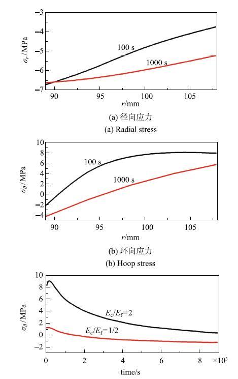
ͼ7��ʾ�������¶�������ɵ�Ӧ���仯[20].���¶�����100$^\circ$F (55.6��) 100s֮��,ˮ��еľ���Ӧ��ΪѹӦ��.����Ӧ����ˮ����ܽ��渽��ΪѹӦ��,��ˮ�/�Ҳ���渽��Ϊ��Ӧ��.��������ˮ��IJ�����������ɵ�,���¶����ߺ�Ľ϶�ʱ����,ˮ��ڵ��¶��ݶȽϴ�,�ڲ��¶ȸ�,����Ӧ���.�������ܵ�������ͽ�С�����Լ��,��˲���ѹӦ��.��������ܵ��ڲ����͵�����,��������Ӧ��.����ʱ����ӳ�,ˮ��ڵ��¶ȷֲ����Ӿ���,��Ӧ����Ӧ���ֲ�Ҳ���Ӿ���.����ѹ��Ӧ������,��������Ӧ������. ��ͼ7(a)��ͼ7(b)���Կ���,����Ӧ��ΪΣ��Ӧ��,�ر���ˮ�/�Ҳ���渽���Ļ���Ӧ�����п��ܵ����������Ƶij���.ͼ7(c) ��ʾ��ˮ�/�Ҳ���洦�Ļ���Ӧ����ʱ��ı仯.���¶����ߺ��˲��,���洦�Ļ���Ӧ��ֱ�Ӵﵽ�dz��ߵ���Ӧ��ˮƽ,���ݼ������ߺ�����.��ͼ�п��Կ�����Ӧ����ˮƽͬ����ˮ��/�Ҳ�ģ���ȵ�ǿ��Ӱ��,��$E_{c}/E_{\rm f}$ ��2���͵�1/2ʱ,���洦�����Ӧ����9MPa���Ҵ�����͵�Լ1.4MPa,���һ���Ӧ��Ѹ��������Ӧ����Ϊѹ��Ӧ��.�����ģ����С��ˮ��п��ֿܵ����ߵ��¶ȱ仯.
 ��ʾԭͼ|����ԭͼZIP|����PPT
ͼ7ˮ��е���Ӧ��
-->Fig. 7The thermal stress in the cement sheath
-->
1.3 �̾�ˮ���ʧЧģʽ��ʧЧ�о�
��һ��������ˮ��е�Ӧ���ݻ���Ӱ������.��ˮ��е�Ӧ��������ȫ��ֵʱ,ˮ����ܷ���������ʽ���ƻ�$^{[21,34\mbox{-}36]}$,���ܽ�Ϊ���֣�(1)��϶,(2)�����ƻ�,(3)��������,(4)��Ƭ״����,��ͼ8��ʾ.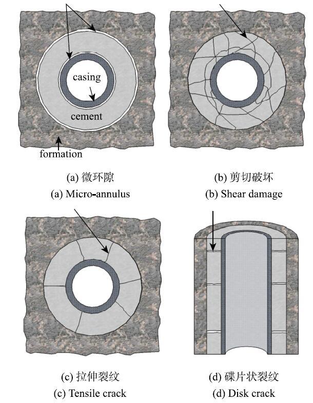 ��ʾԭͼ|����ԭͼZIP|����PPT
ͼ8ˮ���ʧЧģʽʾ��ͼ
-->Fig. 8The failure modes of cement sheath
-->
ˮ��ڹ̻������л�����,����ѹ�����¶�ͻȻ����Ҳ�ᵼ��������,�Ӷ����¾���Ӧ����Ϊ����״̬.ˮ������Լ��Ҳ�Ľ��ǿ��һ��С��������ǿ��,��������ڽ��洦������������,�γ���϶,�ر�����ˮ����ܽ��洦.������Ϊˮ��еľ�����Ӧ���ڸý��洦�ﵽ���ֵ,��ˮ��ͽ����ܵ�ճ��ǿ�Ⱥ���.����̾�֮ǰû�н��꾮�ཬ�����ɾ�,����һ�����ͽ���ǿ��,�ٽ���϶����[37].��ѹӦ������ijһ�ٽ�ֵʱ,ˮ����������ƻ�,�γ�����״�ļ��д�(ͼ8(b)).��������Ӧ������ʱ,ˮ��в�������״���ſ�������(ͼ8(c)).�������ƿ��ܹᴩˮ����,���ڸ߶ȷ����ϴ�����ǧ��.��Ƭ״������Ҫ������ˮ����������������Ӧ���������,��һ������ֲ����������߶ȷ���.��϶��ˮ��ڵ������������Ƹ������ṩ���ظ߶ȷ��������Ƶ�ͨ��,��ɲ�λ�����ʧЧ,��Ҫ��ˮ���ƺͰ�ȫ�����������ص��ע.
Ŀǰ,�����в��õ�ǿ�ȷ�������[20-21]������ˮ��е�ȱ��,�����ߵ�����ѧ�������е�Ӧ����,������ǿ������ȷ��ˮ��ƻ����ٽ�����.���ַ�����������ȷ������ˮ��ܳ��ܵ��ٽ繤��״̬,����Ϊ��֪�ľ��»�������ҵ������������㹦��Ҫ���ˮ�.�÷���������Ԥ��ˮ��ļ����ƻ�.��������϶���������ƺ͵�Ƭ״���Ƶ��ſ�������,ˮ�������Զ����ǿ�ȵ��������ƻ�,ǿ�����۲���������Ԥ����ЩʧЧģʽ.Ulm��[31]���ö�����ѧԤ��������ˮ��еľ�����չ.Wang��[32]�о���������������չ���ٽ�����,�ṩ��һ���ж�ˮ�״̬���ٽ簲ȫ��.������Ҫ����ˮ��г�ʼ���Ƶ�״̬,ֻ�����ڲ��ϵ����ʺ���ҵ����.
ѡ�������ʧЧ�о�,��ȷԤ��ˮ���ʧЧ,�����ɿ������ģ�;�����Ҫ����.�����г����ֳ���ʧЧģʽ��ʧЧ�о�.
(1) ����ʧЧ. Mohr-Coulomb ������Ԥ��ˮ�����ѹ�����ƻ�
\begin{equation} \label{eq1} \tau _{\rm f} = c + \sigma \tan \varphi\tag{1} \end{equation}
ʽ��,$\tau _{\rm f}$Ϊˮ��Ŀ���ǿ��,$\sigma$Ϊ���л������ϵķ���Ӧ��,$c$Ϊ�����ھ���,$\varphi $Ϊ������Ħ����.
(2) ��������.
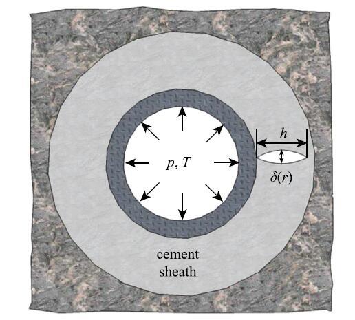
��������������������ˮ�/�ܽ��洦,�������ؾ�����չʱ,���Ƶ��ſ�λ��$\delta$��λ��$r$�ĺ���(ͼ9),�Ѽ�������ͷ���Ϊ[30]
\begin{equation} \label{eq2} G = \frac{1}{2}\frac{{\rm d}}{{\rm d}h}\int_0^h {\sigma _\theta \left( r \right)\delta \left( r \right){\rm d}r}\tag{2} \end{equation}
ʽ��,$\sigma _\theta \left( r\right)$Ϊͬ�����غ�������,���ˮ��еĻ���Ӧ��.�����ſ�λ�ƿ�������Ԫ������ֺ��������. ������չ���ٽ�����Ϊ$G =\varGamma _{\rm c}$,ʽ��$\varGamma _{\rm c}$Ϊ�̻�ˮ��Ķ�����,���С����ʵ������õ�[38].
 ��ʾԭͼ|����ԭͼZIP|����PPT
ͼ9�������Ƶ��ſ�λ��ʾ��ͼ[
-->Fig. 9The opening profile of a tensile crack[
-->
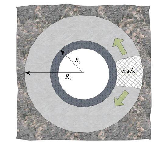
(3) ����(����)����.�̾�ˮ��ĸ߶�ͨ���ڼ�����������ǧ�ij߶ȷ�Χ��,�ڹ̾���ҵ��ˮ�ཬ�̻�������,���ɱ���ػ���ˮ�����ɸ���ȱ��.��Щȱ������ֲ���ˮ���,�����غɴﵽijһ�ٽ�ֵʱ,һЩȱ�ݿ��ܻῪʼ��չ,�γ�һ��������.ˮ��е����ƿ������ž���������չ,Ҳ��������������չ,��һ�����ӵ���ά����.����,�����ؾ�����չֻ�����ˮ��ֲ����ƻ�,��������λ�������������ص�Ӱ��.�����������������������չ�Ż�����ʧȥijһ�λ�������IJ�λ�������.Wang��[32]�����������������߶ȷ�����չ�����Ƴ�Ϊ"��������"(ͼ10).
 ��ʾԭͼ|����ԭͼZIP|����PPT
ͼ10����(����)����ʾ��ͼ[
-->Fig. 10Schematic of a tunneling crack in the cement sheath[
-->
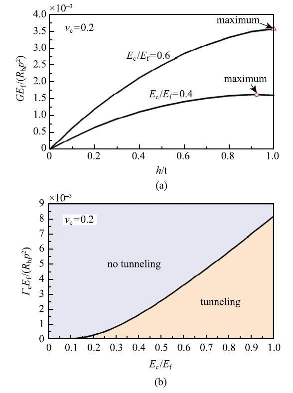
�������Ƶ������ͷ��� $G$����Ϊ�������Ÿ߶ȷ�����չ��λ���ʱ,ϵͳӦ���ܵļ�����.�������������̶�ʱ,�������Ƶ������ͷ����������Ƴ��� $l$ ����.��$l/h >2$ʱ,�������ƴﵽ��̬��չ��,�������ͷ��ʲ�������$l$�仯[39].����һ���Ѽ������ͷ���Ϊ[40]
\begin{equation} \label{eq3} G = \frac{1}{2h}\int_0^h {\sigma _\theta \left( r \right)\delta \left( r \right){\rm d}r}\tag{3} \end{equation}
�����Ϳ��Խ����ӵ���ά����ת��Ϊ�������ƽ��Ӧ������.
��ʽ(3)�ɼ�,�����������̶������,�Ѽ������ͷ��������ƿ���$h$�ĺ���,��ͼ11(a)��ʾ.��������ͷ��ʵ����ֵС�ڲ��ϵĶ�����,�����Ʋ������;��߶ȷ�����չ;��ˮ��/�Ҳ�ģ����Ϊ������,�����ٶ�����Ϊ������,�ɵ�ˮ��İ�ȫ/ʧЧ״̬ͼ,��ͼ11(b)��ʾ. �����ٽ���������ƽ��ֳ�������,һ�ǰ�ȫ�� (notunneling),��ͼ��dz��ɫ����,����һ�����κγߴ�ij�ʼ���ƶ�����������ˮ��߶ȷ�����չ;����DZ��ʧЧ��(tunneling),��ͼ�����½�����ɫ����,����һ����,ˮ��е�ijЩ��ʼ���Ƶ������ͷ��ʿ��ܻᳬ�����ϵĶ�����,�Ӷ���չ����������,���²�λ�����ʧЧ.
 ��ʾԭͼ|����ԭͼZIP|����PPT
ͼ11(a)�����������ͷ��ʺ����ƿ��ȵĹ�ϵ,(b)ˮ��İ�ȫ��ʧЧ����ͼ[
-->Fig. 11(a) The normalized energy release rate as a function of the normalized width of the tunnel, (b) failsafe diagram in the plane with axes of the normalized Young's modulus and normalized fracture energy of the cement[
-->
(4) ��϶. ��϶�������ͷ��ʱȽ�����ȷ��[31]
\begin{equation}\label{eq4} G = \frac{1}{2}\sigma _r \delta _{\rm i}\tag{4}\end{equation}
ʽ��,$\sigma _r $Ϊ��ýṹ�ڽ��洦�ľ���Ӧ��,$\delta _{\rm i}$Ϊ���洦����϶�ſ�λ��. ����,��϶�Ľ������������ȷ��.һ��ˮ�ࡢ�ܼ��Ҳ��ճ��ǿ�����Բ���,���ǽ���ǿ���ܵ��̾����ա��ཬ�����̶ȵȶ�����ص�Ӱ��.
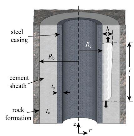
(5) ��Ƭ״����.����ˮ��ļ�������,��Ƭ״��������ܵ���չ·����ͼ12��ʾ,���Ѽ������ͷ���Ϊ
\begin{equation} \label{eq5} G = \frac{1}{R_{\rm b}^2 - R_{\rm c}^2 }\int_{R_{\rm c} }^{R_{\rm b}} {\sigma _z \delta \left( r \right)r{\rm d}r}\tag{5}\end{equation}
ʽ��$\delta _z $Ϊ$z$����������ſ�λ��.�������ͷ��ʴﵽˮ�������ʱ,���ƿ�ʼ��չ.
 ��ʾԭͼ|����ԭͼZIP|����PPT
ͼ12��Ƭ״������չʾ��ͼ
-->Fig. 12Schematic of disk crack extension
-->
1.4 Ӱ��ˮ�ʧЧ�Ĺؼ�����
�о�����,ˮ��������Բ�����ˮ�౾���������������,�����Ҳ㡢�ܵ���ѧ�����Լ����β������$^{[20,23, 35]}$.�ڹ������ܺ��Ҳ����ز��������϶���ȷ����,�ܹ�ͨ������Ը���ˮ����������ԵIJ�����Ҫ�����¼�����(1) ˮ��/�Ҳ�ģ����. ��ͼ6��ͼ7(c) �ɼ�,��$E_{\rm c}/E_{\rm f}$����ʱ,��ѹ�����¶ȱ仯���µ���Ӧ������������,�Ӷ�����������չ������(ͼ11(a)).������Ҳ����,������ĭˮ��ȵ�ģ��ˮ�������������ij��ڲ�λ�������[41].����,Petersen[22]���о�����,��ˮ��̻���,��Ӳ�Ҳ��ʹˮ��ڲ����ϴ�ij�Ӧ��,�������ˮ�ʧЧ.�����������Ҳ����ѧ���ܱ仯��Χ�ܴ�,��ģ���仯��ΧΪ1$\sim$30GPa [20].���,��һˮ���������������,������ض����»���ѡ����ʵ�ˮ��.
(2) ˮ��ɱ�. ���Ź̾�ˮ��ijɷֱ仯,�䲴�ɱȿ���0.1$\sim$0.4��Χ�ڵ���[36].����ˮ��IJ��ɱȽ�С,ͨ�����������ȿ�����䲻��ѹ���ԺͲ��ɱ�ֵ.��ͼ7��ʾ,�߲��ɱ������ڽ��ͻ�����Ӧ��ˮƽ,������ʹ��Ӧ����ΪѹӦ��,�Ӷ����Ͳ����������Ƶļ���.���,ˮ��--���ϲ����DZȽ�����Ĺ̾�����[8].
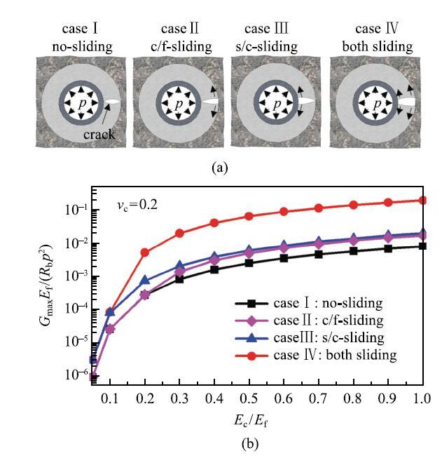
(3) ����ǿ��.ˮ������Լ����ڵ�ճ��ǿ��ֱ��Ӱ����϶����������չ.ͬʱ,���滬�ƶ�ˮ����������Ƶ���չҲ����Ҫ��Ӱ��[32].��ͼ13��ʾ,��������ճ����ʱ,�������Ƶ������ͷ�����������.ˮ�����Ľ�����,ˮ����ܽ����Ӱ�����.���,����ճ��ǿ�ȶ�ˮ��IJ�λ�������������Ҫ.��������������,�����ͻ��꾮Һ����Ⱦ,ˮ������Լ����ڵ�ճ��ǿ��ͨ���Ƚ���,���������ֱ�Ӹ��뿪,�Ӷ�ʧȥ�Ӵ�[37].�ɼ�,�ཬ���������������ˮ��ij�����������Ҫ����.
 ��ʾԭͼ|����ԭͼZIP|����PPT
ͼ13ˮ������Լ��Ҳ�Ľ�����ѧ���ܶ��������������ͷ��ʵ�Ӱ��[
-->Fig. 13The effect of interfacial sliding on the energy release rate of tunneling crack[
-->
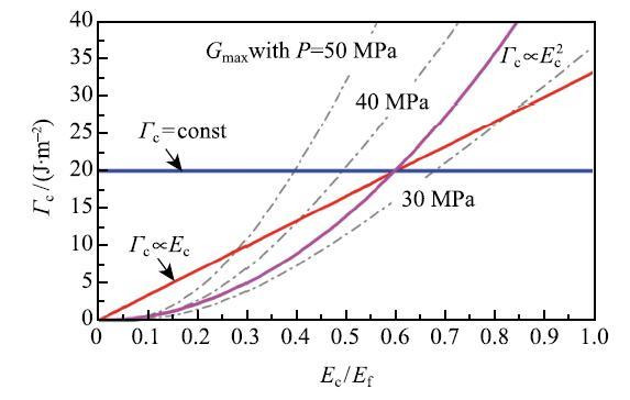
(4) ��������.����ǰ�о���,��������ʶ����ˮ��ģ����ˮ���ȫ�Ե���ҪӰ��[16, 20-21, 36].���̻�ˮ���ģ�������ڽ����������Ƶ������ͷ���,����С������չ������.����,����ȴ������Ӱ��������չ�ٽ���������һ����Ҫ���أ�ˮ��Ķ�������,��ˮ����ϵֿ�������չ������.���ϵ�ģ���Ͷ��������������һ�����������,��ˮ��ģ������ʱ,�����������Ҳ����֮�½�[38].���,����ˮ��ĵ���ģ������һ�������ˮ��İ�ȫ��,��Ҫ����ˮ��Ķ����ܺ͵���ģ��֮��Ĺ�ϵ.Wang��[32]���������ּĹ�ϵ,��ͼ14��ʾ��������Ϊ����;��������ģ�����Ա仯;��������ģ���Ķ��κ���.����Ϊ��Ӧ������ѹ��$p = 30$,40 ��50 MPa����������ͷ���.��������Ϊ����ʱ,����ˮ��ģ������Ч������ٽ��غ�,������������ģ���Ķ��κ���ʱ,����ˮ��ģ�������������Ӱ�첻��.����������ģ���½�����,��ģ�������п��ܽ������������.
 ��ʾԭͼ|����ԭͼZIP|����PPT
ͼ14ˮ��Ķ����ܺ�ģ��֮��Ĺ�ϵ���������Ե�Ӱ��[
-->Fig. 14The correlation between the fracture energy and elastic modulus of cement and its effect on the integrity of cement sheath[
-->
2 ����ʽ�ߵ�����
�ߵ���������������������һ����Ҫ���ܷ��.��ͳ�ߵ�����������������Ϊ�ܷ�Ԫ��,ͨ����е��ѹʹ�������Ͷ�ʵ���ܷ�[9],��ͼ15(a)��ͼ15(b)��ʾ. ��ȱ���Dz�������,�ܹ��ܷ�Ļ��ճߴ��ѹ��������.ǰ������,ˮ���ܷ����а�������ʷ.���֮��,����ʽ�ߵ����ܷ��������·�չ�������ܷ⼼��,2001���һ�α�Ӧ�õ�����ʵ����[42].����ʽ�����������ˮ�����͵ĸߵ���ۺ�����Ϊ�ܷ�Ԫ��[43-44],���ߵ�����������Һ��(�ͻ�ˮ)֮��������ЩҺ�巢��������Ͳ��;��ڽӴ�,����һ���ĽӴ�ѹ��(ͼ15(c)),��һ���̿�����Ҫ����������,ȡ���ڸߵ���IJ������ʡ�������ļ��γߴ�;��»���(�����¶ȡ��������ʡ��������ʵ�).���еʽ��������,����ʽ��������гɱ��͡��ṹ��������㡢����ռ���ѹ���ߵ��ŵ�.�ر��ǵ������������ˢ�ߴ���ʱ,�ߵ����ܼ��������ֲ����۳ߴ�ı仯,ά���ܷ�״̬.��Щ�ŵ�ʹ��������������Ѹ�ٵõ��˹㷺Ӧ��,2010���������г������������ʽ��������õ�������ص���������[42],���ѳ�Ϊ����Ҫ�ķ������.�����ص��������ʽ�������һ�µķ������,���������͡����κ��ƻ��Ļ�������,���Է�����ʧЧģʽ.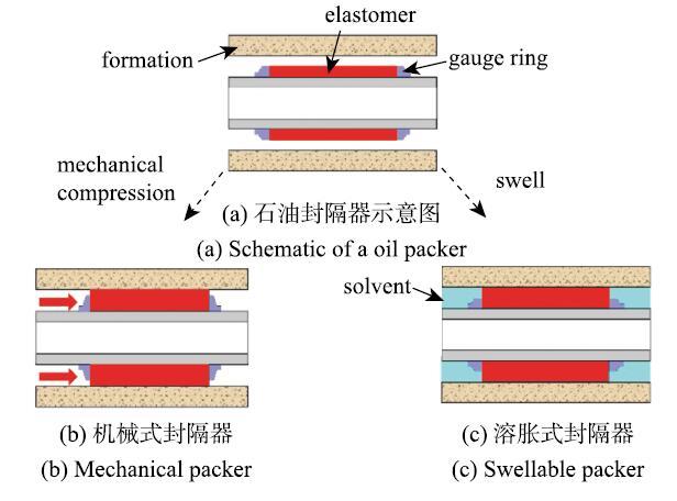 ��ʾԭͼ|����ԭͼZIP|����PPT
ͼ15�ߵ��������Ľṹ������ԭ��ʾ��ͼ
-->Fig. 15Schematic of the structures and work principles of elastomeric seals
-->
2.1 �ߵ����ܷ��ʧЧģʽ��ʵ�鷽��
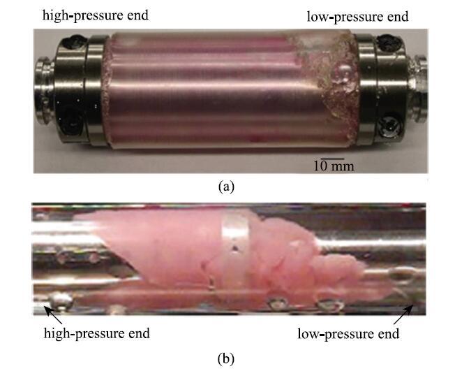
�ھ�����ҵ��,�ߵ���������Ҫ��ֹ�����˵����廥����ͨ,��ά��һ����ѹ����.����,�༶ˮ��ѹ���иߵ�������������Ҫ����Լ70MPa������ѹ����[45].������ѹ������������ij�������ʱ,�ߵ����ܷ�Ԫ��������ι������Ѷ����·������й©.���ڸߵ��������ڼ��ٵ���ǧ����ľ��¹���,������Ա��ʵʱ�۲������ı��κ�й©���.Ϊ��,��������Ҫ����ȫ�ߴ�ģ�������Է����������ѹ���µ���Ӧ[43, 45]. Nijhof��[45]��ʵ�����в�������������������ʽ������ڸ�ѹ���������µ�й©���ƻ����,����װ����ͼ16��ʾ.���ý�����ģ�⾮��,������5 m���ķ��������������������֮��,�ȴ�һ��ʱ��ʹ�ߵ���ۺ������Ͳ�������ܽӴ�,������һ���ĽӴ�ѹ��.�����������Ӹ�ѹ�ò���ѹ,3��ѹ����ʵʱ������˺ͷ����֮���ѹ��,������ѹ������,�����������̷���й©.֮��ʵ����Ա���,�۲�������ʧЧģʽ.�ڵ�һ��������й۲쵽һ���ᴩ�����ܷ�Ԫ�����ȵ�ͨ��,ͨ�������ƻ���С���������ѹҺ������,�������ֱ������,�ڽ�������Լ���±�����ԭ��(ͼ16(b)).���ڵڶ��������,���ڸ�ѹһ����ֲ��ƻ�,���������ȷ�����,���ֲ���û�з����ƻ��ļ���(ͼ16(c)).���ַ�����ʱ��,��Ҫ���ӵĸ�ѹ�豸,�۸�.��ʵ��װ��Ҳ��ʵʱ�۲�ߵ����ܷ�Ԫ���ı��κ��ƻ����,ֻ����ʵ�����֮��ͨ���и��Լ��۲����ƻ����״̬.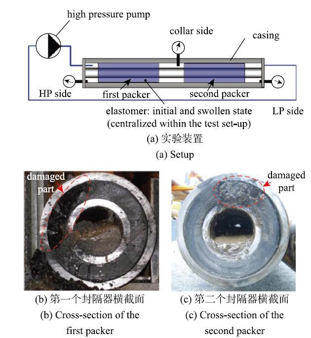 ��ʾԭͼ|����ԭͼZIP|����PPT
ͼ16����ʽ�������ȫ�ߴ����[
-->Fig. 16Full scale test on the swellable packers[
-->
�����һ����,Druecke��[46]���ù����������ͷ����,��������ʵ��װ��ʵʱ�۲��ܷ����������ѹ�������µı��Ρ��ƻ���й©,ʵ��۲쵽���ƻ�ģʽ,��ͼ17��ʾ.ͼ17(a)�Ǿ۶�����������(PDMS)�ͷ����,��й©����ķ�������Կ���,�ڷ�������˿�������������,���������ƻ�,�����������ֲ����Ա�������.��Һ��ѹ����������,��һ�ֹ������ (ͼ 17(b))�����˷dz���ı���,���кܴ�һ���ֲ��ϱ�������ѹ�˵Ľ�������,���������С��Ƭ,���շ���й©.
 ��ʾԭͼ|����ԭͼZIP|����PPT
ͼ17����ʽ�����ģ�͵�����ʧЧģʽ[
-->Fig. 17Two failure modes of mini swellable packers[
-->
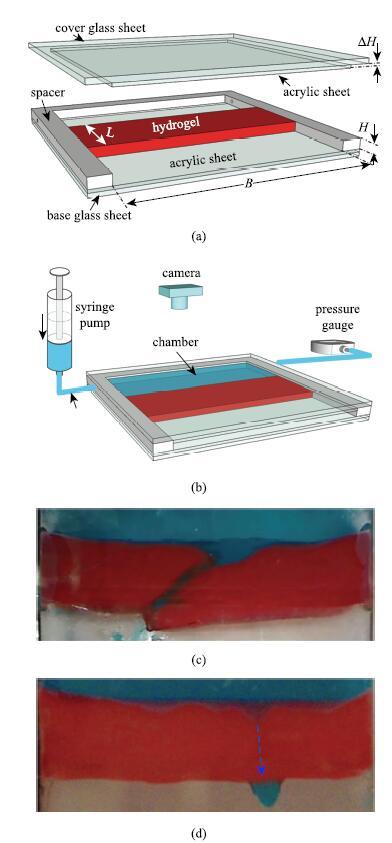
Wang��[47-48]���������Ʒ��������һ����ʵ��װ��,��ͼ18��ʾ,������ˮ������Ϊģ�Ͳ���,�䵯��ģ���ȸߵ���ģ������3��������,��������Ӧ������ѹ��Ҳ������3��������,����ؽ�����ʵ���ѶȺ�ʵ��ɱ�.���,�������ü�����ʵ��װ�ý��в���.�ڸ�װ����,��ˮ�����ײ�ճ�ӵ����ǿ�������,����ճ�ӵ�һ��U�͵�Ƭ��,����Ƭ�Dz�Ƭճ�ӵ�һ��ʱ,ˮ������Ԥѹ��,�Խ����Ӵ�ѹ��.ˮ�����Ͷ����ǿ�����֮��û��ճ��,�������鲣��Ϊˮ�����ṩ����Լ��.ˮ�������ǿ�����͵�Ƭ�γ���һ���ܷ�ǻ��,��ͼ18(b)��ʾ,��ͨ�����ϵ��ܺ�ע����Լ�ѹ��������.
 ��ʾԭͼ|����ԭͼZIP|����PPT
ͼ18������ʵ��װ�ú����ø�װ�ù۲쵽������ʧЧģʽ[
-->Fig. 18Transparent desktop setup, and two failure modes observed by using this setup[
-->
ʵ����ע����Ժ㶨��������ǻ����ע��ˮ,����¼ע�����$Q_{\rm i}$��ѹ��$p$. ͬʱ�������������¼ˮ�����ı��κ�й©.Wang��[47-48]�۲쵽����й©�͵���й©����ʧЧģʽ,��ϵͳ�о��˼��β����Ͳ��ϲ������ٽ�й©ѹ����Ӱ��.
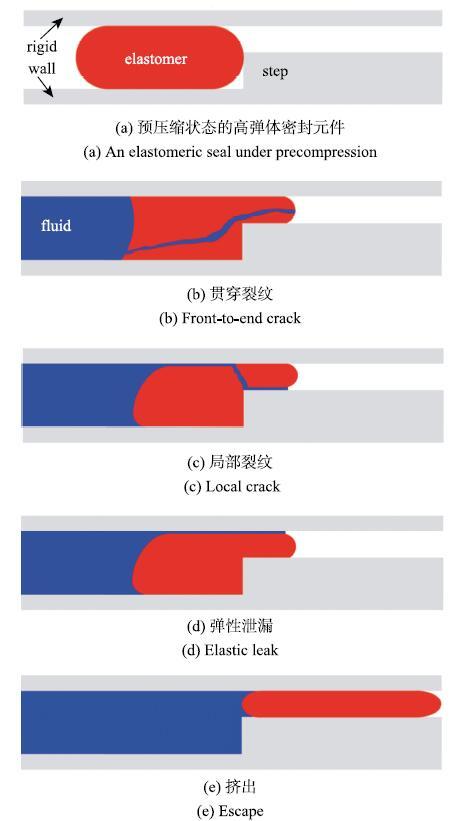
�����������ߵ��о����,�ɽ��ߵ����ܷ�Ԫ����ʧЧģʽ�ܽ�Ϊͼ19��ʾ�ļ�����ʽ.�ߵ�����ϱ�Լ�������������֮��,�Աߵ�̨����ֹ�ߵ�������,����ֹ�ߵ��������ܷ�λ��.����ߵ���һ��ʩ������ѹ��ʱ,�ߵ������,�����ѹһ�༷��.������ѹ�����ӵ�һ���̶�ʱ,��ѹ�˿�������һ������,���س��ȷ���ᴩ�ߵ���(ͼ19(b)),�Ӷ��γ�һ������й©ͨ��.������̨������������,�������IJ����е�,���������ֱ������(ͼ19(c)).������ʧЧģʽ�ڴ�ͳ�����ܷ�ȦҲ���۲쵽[49].
 ��ʾԭͼ|����ԭͼZIP|����PPT
ͼ19�ߵ����ܷ�Ԫ����ʧЧģʽ[
-->Fig. 19Failure modes of elastomeric seals[
-->
�ߵ����ܷ�Ԫ���������ڲ������κ��ƻ��������й©(ͼ19(d)).
�������Ÿߵ����Լ������֮��Ľ���й©.����ģʽ����Ϊ����й©,���ܷ�Ԫ������Ϊ�ߵ���ĵ��Դ���ζ�����й©[47].����ߵ�����Χ��Լ������,�ܷ�Ԫ�������п��ܱ������ܷ�λ�ö�й©(ͼ19�).ÿ��ʧЧģʽ��Ӧһ�����ٽ�ѹ��,������͵��ٽ�ѹ����������ʧЧģʽ.
2.2 �ߵ�������������
�ߵ���ۺ����ɴ����ĵ���ͨ�����ۼ������ۺ��γ���ά����״�ṹ.���ߵ���ۺ����Һ��Ӵ�ʱ,�߷����ϵ�ijЩ���ܻ���(����ˮ�Ի��š������Ի���)�ͻ��ʹҺ������������С����(�ܼ�)���뵽�߷��������ڲ�,���¸ߵ������ͱ���,ֱ�������غɺ���Χ�Ļ�ѧ�ƹ�ͬ�����´ﵽƽ��״̬.�߷��Ӿۺ�����ܼ�С���ӵļ����屻��Ϊ��������.���������ܵ����������仯ʱ,�ڶ�ʱ����,�ܼ�С���ӻ��������ڸ߷���������Ǩ��,�����µ�Ӧ��ƽ��״̬�Ѿ�����,��һ����ֻ�漰���߷������繹�͵ĸı�,������״�����ı�,�����������;�ڳ�ʱ����,�ܼ�С�����ڸ߷��������л����·ֲ�,ʹ����������״������������仯,��ʱ���㹻��ʱ,����������е�غ��Լ���Χ�ܼ��Ļ�ѧ�ƶ��ﵽƽ��״̬[50-51].�ɼ�,����������һ�����ӵ�����ѧ����,����[52,53,54]������ѧ�����,�����˿��Ǵ���κ��ܼ���ɢ������ģ��,Liu��[55]����һ��������ϵͳ����,�������Լ���.
ȡ�ο�״̬�����Ϊ${\rm d}V( X)$��Ԫ����Ϊ�о�����,�����Թ��ԺͶ��ܵ�Ӱ��,�ܼ������ڸߵ��������ڵ���ɢ���̿�������һϵ�з��̾�����
(1) �����ݶ�. �ڳ�ʼ������,һ�����ʵ������Ϊ$X$.��ʱ��$t$,���ϱ��ε���ʱ״̬,���ʵ�$X$�������Ϊ$X$.����$x( X,t)$�����˾ۺ�������ı�����ʷ,���ϵı���״̬�����α���������ʾ,�����ʽΪ
\begin{equation} \label{eq6} F_{iK} \left( { X,t} \right) = \frac{\partial x_i \left( { X,t} \right)}{\partial X_K }\tag{6} \end{equation}
(2) �ܼ������غ㷽��.��������������û�л�ѧ��Ӧ����,����ܼ����ӵ�����Ӧ���غ�,�������ڲ������ϵ
\begin{equation} \label{eq7} \frac{\partial C\left( { X,t} \right)}{\partial t} + \frac{\partial J_K \left( { X,t} \right)}{\partial X_K } = r\left( { X,t} \right)\tag{7} \end{equation}
���������ϵ
\begin{equation} \label{eq8} J_K \left( { X,t} \right)N_K \left( X \right) = - i\left( { X,t} \right)\tag{8} \end{equation}
ʽ��,$J_{K}( X, t)$Ϊ�������ܼ����ӵ�����ͨ��,$r( X,t) {\rm d}V( X)$Ϊ��λʱ����ע�����Ԫ����ܼ�������Ŀ,$i( X,t){\rm d}A( X)$Ϊ��λʱ���ڴӵ�Ԫ�������ķ�����Ŀ.
(3) ��ƽ�ⷽ��. ��Ԫ��������
\begin{equation} \label{eq9} \frac{\partial s_{iK} }{\partial X_K } + B_i = 0\tag{9} \end{equation} �ڱ߽������� \begin{equation} \label{eq10} s_{iK} N_K = T_i\tag{10} \end{equation}
����,$s_{iK}$Ϊ����Ӧ��,$B_{i}$��$T_{i}$�ֱ�Ϊʩ���ڵ�Ԫ�ϵ�������������$i$�����ϵķ���.
(4) �ֲ�ƽ������.�������ڴﵽ����ƽ��״̬֮ǰ,�����в�ͬ�IJ��ϵ�Ԫ���ڷ�ƽ��״̬,���ڵIJ��ϵ�Ԫ֮����ڻ�ѧʽ�ݶ�,������Һ���������������ɢ.��Ȼ�������������������ϴ��ڷ�ƽ��״̬,���������ڲ��IJ���Ԫ�������Ϊ����ƽ��״̬��.������Ϊ�������ɢ��һ���dz������Ĺ���.���ϵĹ��Կ��Ժ���,����Ԫ�ڲ���𤵯�Թ������㹻��ʱ���ɳ�,Ԫ���ڲ���Һ�����Ҳ���㹻��ʱ�����Χ�Ļ�ѧ��ƽ��.�����
\begin{equation} \label{eq11} s_{iK} = \frac{\partial W\left( { F,C} \right)}{\partial F_{iK} }\tag{11} \end{equation} \begin{equation} \label{eq12} \mu = \frac{\partial W\left( { F,C} \right)}{\partial C}\tag{12} \end{equation}
ʽ��,$W( F,C)$Ϊ�������������ܶȺ���,$\mu $Ϊ�ܼ��Ļ�ѧ��.��Ҫ˵������,���˱�����,�����������ֵ�$\mu $�������ϵļ���ģ��.
(5) ��ɢ����ѧ����. ����ʱ������,��ɢͨ��$j$�뻯ѧ��$\mu$�Ĺ�ϵΪ[56]
\begin{equation} \label{eq13} j_i = - \frac{cD}{kT}\frac{\partial \mu }{\partial x_i }\tag{13} \end{equation}
ʽ��,$c$Ϊ��ʱ�����е�λ����ڵ��ܼ���������,$D$Ϊ��ɢϵ��,$k$Ϊ������������,$T$Ϊ����ѧ�¶�.
(6) ����ѹ������. ���������е����з��Ӷ��Dz���ѹ����.���,������������ڴ��߷������������������յ��ܼ������,����
\begin{equation} \label{eq14} 1 + \nu C = \det \left( F \right)\tag{14} \end{equation}
(7) Ӧ�����ܶȺ���.���������������������ַ��ӹ��̣��߷��������������κ߷���������Һ��С���ӵĻ��.����Flory��Rehner[57]������,�����ܺ������Բ������µ���ʽ
\begin{equation} \label{eq15} W\left( { F,C} \right) = W_{\rm s} \left( F \right) + W_{\rm m} \left( C \right)\tag{15} \end{equation}
��������������ܺ���$W_{\rm s}( F)$�ɲ��ó��õĸ߷��Ӿۺ���������ܺ���[58-63].��������,ͨ������Floryģ��[64]���������α�������
\begin{equation} \label{eq16} W_{\rm s} = \frac{1}{2}NkT\left[ {F_{iK} F_{iK} - 3 - 2\lg \left( {\det \left( F \right)} \right)} \right]\tag{16} \end{equation}
��Floryģ����,����Neo-Hookenģ��[58]��Gentģ��[59]��Mooney-Rivlinģ��[60-61]��Ogdenģ��[62]��Arruda-Boyceģ��[63]��.��ͬ����ģ�ͶԲ�ͬӦ�������Ӧ��Ӧ���ϵ��������������ͬ,�����Ҫ���ݾ�������,ѡ�ú��ʵIJ���ģ��.������Dz��ϵ�𤵯�Ժ�MullinsЧӦ,����Ҫ�µIJ���ģ��[65-66].���õĻ�������ܺ���Ϊ[67-68]
\begin{equation} \label{eq17} W_{\rm m} \left( C \right) = - \frac{kT}{\nu }\left[ {\nu C\log \left( {1 + \frac{1}{\nu C}} \right) + \frac{\chi }{1 + \nu C}} \right]\tag{17} \end{equation}
����,$\chi $Ϊ�����ٲ���. ��$\chi <0$ʱ,���������Һ����������ڲ�;��$\chi> 0$ʱ,���������Һ��������ڲ�������ɢ.
������������,�Լ���������ı߽������ͳ�ʼ����,����ȷ���ߵ������͵Ŀ��Ʒ���,ģ���е���ز�������ͨ��ʵ������õ�[69-70].����,���ڷ�����Ĺ��ͺͱ߽������Ƚϸ���,���Եõ��Ľ�����.ͨ�������ǽ���Щ����ģ��ֲ�뵽����Ԫ������,ͨ����ֵ������Ԥ�����������ܷ�״̬��ʱ��ͽӴ�ѹ���ı仯����[71-76].
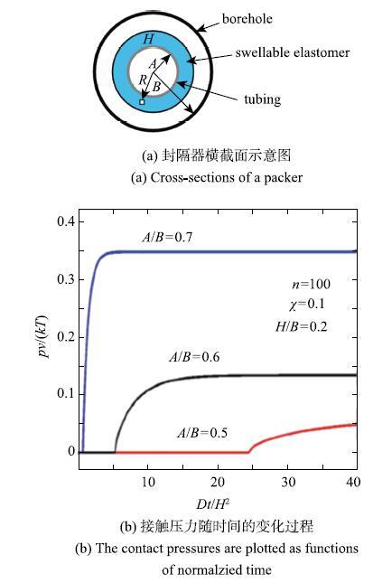
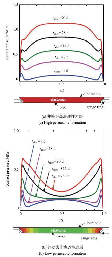
Cai��[73]����ƽ��Ӧ��ģ��,������ߵ���ۺ��������������������,�����˸ߵ���������������,��ͼ20��ʾ.�����۳ߴ�ߵ����ȱ�һ��ʱ,������;���֮��ij�ʼ��϶ԽС,�ߵ����Խ��;��ڽӴ�,���ҽӴ�ѹ��Խ��.Lou��Chester[76]����Chester��[75]������ABAQUS�û��ӳ���,�����˸ߵ�����������������,�ܷ�Ԫ�����ȷ���ĽӴ�ѹ���ֲ���ʱ��ı仯����.�ڼ�����,���Dz����˿����Ժͷ��������ֲ�ͬ���Ҳ�߽�����.�������,�����ڱ��趨Ϊ�������Ҳ�ʱ,���ͽϿ�,���Ӵ�ѹ���ڷ�������в�,��ͼ21��ʾ.���Ҳ㲻��������ʱ,�ۺ��������൱����,�����Ӵ�ѹ���ڸߵ������˽ӽ�����������,��˵���м䲿�ֵIJ���û�г������,�ܷ�Ч���Ƚϲ�.�ɶ��������[50-51]��֪,���Ҳ��������ʱ,�ߵ��忿�����ڵĽ����ܹ��Ӵ���������,�ܼ�������Ҫ�Ӿ������ڲ���ɢ,�ߵ������͵�����ʱ��߶�Ϊ$t~H^{2}/D$,����$H$Ϊ�ߵ���ĺ��,$D$Ϊ�ܼ��ڸߵ����е���ɢϵ��.�����ڲ��������Ի����ʺܵ�ʱ,�ߵ���ֻ�п��������������뾮������Ӵ�,�ܼ�������Ҫ�Ӹߵ���Ԫ���������м���ɢ,�ߵ������͵�����ʱ��Ϊ$t~L^{2}/D$,����$L$Ϊ�ߵ���Ԫ���ij���.���ڸߵ�������,$L$Զ����$H$.�ɼ�,���ڵ������Լ�������ij��ȶ��ڷ�����������ٶȺ����ķ��Ч���зdz���Ҫ��Ӱ��.��Ҳ˵����ǰʵ�������ý���������ģ�⾮�ھ���һ���ľ�����,����ģ��������Ҳ����.
 ��ʾԭͼ|����ԭͼZIP|����PPT
ͼ20����ƽ��Ӧ��ģ�ͼ��������еĸߵ�����ϵ�������[
-->Fig. 20Swelling process of elastomer in a swellable packer under plane strain condition[
-->
 ��ʾԭͼ|����ԭͼZIP|����PPT
ͼ21�ߵ����������ȷ���ĽӴ�ѹ���ֲ�ʾ��ͼ[
-->Fig. 21The distribution of contact pressure along the length of a packer[
-->
2.3 �ߵ��������ı���
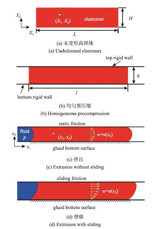
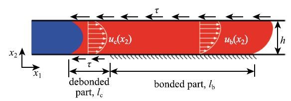
���ߵ���;��ڻ�������ܱڽӴ�������һ���Ӵ�ѹ����,�ܹ���ֹ��������˵���������һ������,��ά��һ����ѹ����.��һ���ѹ������,�ߵ�������,����������ѹ�������������.��ѹ������ٽ�ֵ��,����������ڸߵ�����ι������Ѷ�й©.Wang��[48]������һ���ߵ����ܷ������ģ��.��ģ�������������ߵ����ܷ�Ԫ��������ѹ���µļ�������,�ߵ������ǽ�������Ի���,���Ƶ������ʹ�������.��ͼ22��ʾ,����һ���ʼ����Ϊ$L$,�߶�Ϊ$H$,���Ϊ$B$�ĸߵ���.����ߵ����غ�ȷ�����ȱ���,���ֻ�ÿ�����һ������,��ɼ�Ϊƽ��Ӧ������.�ߵ��屻�������������ǽ֮��,����ѹ�����߶�Ϊ$h$,����Ϊ$l$.���ڸߵ���IJ���ѹ����,$LH = lh$,��������$\lambda = h/H =L/l$,����Ϊ�����ߵ���Ԥѹ���̶���.Ϊ�˻����ʽ���۽�,Wang��[48]����ߵ�����Ԥѹ�������б��ξ���.Ԥѹ��֮��,�ߵ���͵������ǽճ��.���ڲ��ϲ���ѹ��,�κξ��ȵľ�ˮѹ��������������Ӱ��.�ߵ��������䳤�ȷ������һ����ѹ����,��ͼ22(c)��ʾ,�ߵ�������Һ��ѹ������ڻ���ѹ��Ϊ$p$,�Ҳ�Ϊ����ѹ��.������ѹ����Сʱ,�ߵ���Ͷ�������ǽ֮��ľ�Ħ������ֹ������Ի���,�ߵ����������������.������ѹ���ϴ�ʱ,�ߵ�������ڶ�������ǽ����,��ͼ22(d)��ʾ.
 ��ʾԭͼ|����ԭͼZIP|����PPT
ͼ22�ߵ����ܷ�Ԫ����Ԥѹ����������ѹ�������µı��κͻ���ʾ��ͼ[
-->Fig. 22The extrusion and sliding of a piece of precompressed elastomer under fluid pressure[
-->
�ܷ�Ԫ��������ѹ���µ���Ӧ����Ҳ��Ҫ����״̬����������.���ڲ��ϱ��εķǾ�����,�ܷ�Ԫ���ı���״̬������ijһ���Ӧ��״̬������.ģ�����øߵ���ļ������$Q$,���ߵ��崩��ijһ��ֱƽ������,�����������״̬.���ڲ���ѹ������,$Q$ ��$x_{1}$�������.$p-Q$����,������ѹ��--�����������,�ܿ�����һ���ܷ�Ԫ������ѧ��Ϊ,��������ʵ���в���.
�ߵ������ǽ֮���Ħ������ֹ���ߵ���Ի���,��Ӱ���ܷ�Ԫ���ķ������.ģ���м��軬��Ħ����$\tau$Ϊ����,�ⳣ���ڸ��ϲ���ģ����[77],���Һ���������ϵ�Ħ��ʵ���������[78-79].
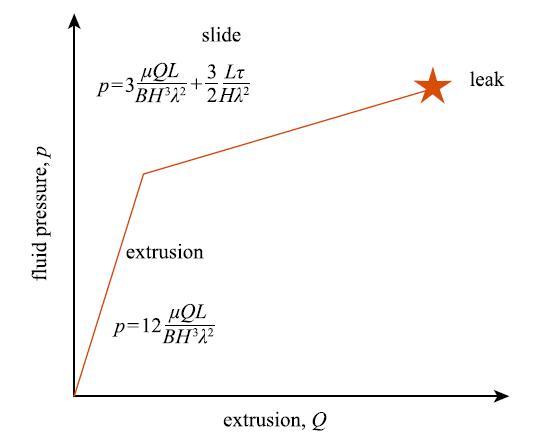
��ģ����,�ߵ���ı��γ�����$x_{2}$�ĺ���,�������ڲ���ѹ������.��������ʽ�����,��ʱ���ڵı��ο��Ժ���������,�����Dz���ѹ����.����Neo-Hookean����ģ��,�ɵ�$p-Q$��ϵΪ
\begin{equation} \label{eq18} p = \left\{ {{\begin{array}{ll} 12\dfrac{\mu QL}{BH^3\lambda ^2}, & p < \dfrac{2L\tau }{H\lambda ^2} \\[3mm] 3\dfrac{\mu QL}{BH^3\lambda ^2} + \dfrac{3}{2}\dfrac{L\tau }{H\lambda ^2}, & p > \dfrac{2L\tau }{H\lambda ^2}\\ \end{array} }} \right.\tag{18} \end{equation}
ʽ��$p = {2L\tau }/{\left( {H\lambda ^2}\right)}$Ϊ���滬�Ƶ��ٽ�����. ���$p < {2L\tau }/{\left({H\lambda ^2} \right)}$,���������Ի���,$u\left( h \right) =0$,���澲Ħ����$\sigma _{12} \left( h \right) = { - pH\lambda ^2}/{\left( {2L} \right)}$. $p > {2L\tau }/{\left( {H\lambda ^2}\right)}$ʱ,����Ħ����Ϊ����,$\sigma _{12} \left( h \right) = -\tau $. $p-Q$Ϊ˫���Թ�ϵ,��ͼ23��ʾ.���ߵ�����濪ʼ����ʱ,б�ʷ����仯. ����ģ��$\mu $Ӱ�������ε�б��,���滬��Ħ����Ӱ�컬����ֱ�ߵĽؾ�.�����ε�ֱ������$Q$��������,ֱ����ʼй©.
 ��ʾԭͼ|����ԭͼZIP|����PPT
ͼ23$p-Q$��ϵʾ��ͼ
-->Fig. 23Fluid pressure extrusion relationship
-->
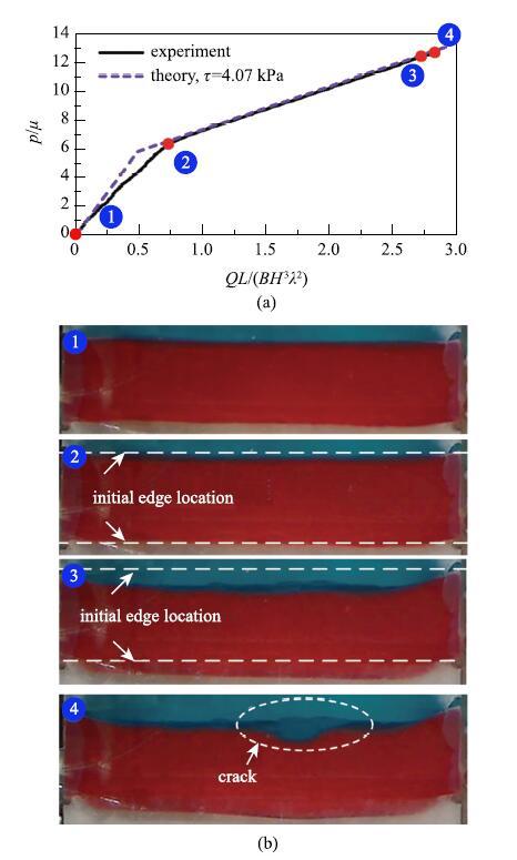
�����ϸߵ���ļ������$Q$����ע���ܷ�ǻ���ڵ�Һ�����$Q_{\rm i}$,���Dz�����ͼ18��ʾ��ʵ��װ��ʱ,���ϵ�����Һ��ѹ����Ҳ������,��˲���ע���Һ�����,$Q_{\rm s}$,���������˵�����,ע���ܷ�ǻ���ˮ�����$Q = Q_{\rm i}-Q_{\rm s}$.ʵ�����������Ԥ���$p-Q$���ߵıȽ���ͼ24(a)��ʾ,�����ǺϽϺ�.��Ӧ�ı��ι�����ͼ24(b)��ʾ,������ѹ���Ƚ�Сʱ(��-��),�����۲첻��ˮ�����ı���;��������ѹ���Ƚϴ�ʱ(��-��),ˮ������Һ��ѹ�����������»���,ֱ��ˮ������������(��).��һ����������ģ�ͼ���һ��.
 ��ʾԭͼ|����ԭͼZIP|����PPT
ͼ24����Ԥ���ʵ�������$p-Q$���߱Ƚ�;(b)ˮ�����ı��κ��ƻ�����[
-->Fig. 24(a) Comparison between the theoretical prediction and experimental measurement on $p-Q$ relation; (b) The deformation and fracture of a hydrogel sample[
-->
2.4 �ߵ���������й©
���2.1������,������ѹ���ﵽ�ٽ�ֵʱ,�ߵ����ܷ�Ԫ�����ܻ���ֶ�����ʽ��й©.�������Ǹ�����Ӱ��,��Ҫ�ж���й©�͵���й©����ģʽ[47-48].�����������й©ģʽ.(1) ����й©.
ʵ���й۲쵽�Ķ���й©���̱Ƚϸ���[48],���Էֳ������Σ���һ�����ܷ�Ԫ����ѹ�˵ײ���������һ������,������ƽ���ڵײ�����ǽ��ǰ����;�ڶ��θ�����ת����һ����ֱ�ڵ��������,�ᴩ�����ܷ�Ԫ��.Wang��[48]�����˵�һ�����ƴ������ٽ�����,����ģ����ͼ25��ʾ,һ������λ�ڸߵ����ѹһ����ײ��ĵط�,����Ϊ$l_{\rm c}$.
 ��ʾԭͼ|����ԭͼZIP|����PPT
ͼ25�ߵ����ܷ�Ԫ���Ķ���ģ��[
-->Fig. 25Fracture model of an elastomeric seal[
-->
�����Ѽ⸽���ߵ������˸���,���������δ���������λ�Ƴ���������$x_{1}$.����ƽ�ⷽ�̺ͱ߽��������Եõ����������λ�Ƴ�,����һ��������Ѽ������ͷ���.�������ͷ��ʴﵽ���ϵĶ�����ʱ,���ƿ�ʼ��չ.���ø��ٽ������ɵ�������չʱ���ٽ�����ѹ��[48]
\begin{equation} \label{eq19} p_f = \frac{\sqrt 6 }{\lambda }\sqrt {\frac{\varGamma \mu }{H}} \frac{L}{H} + \frac{2\tau L}{H\lambda ^2}\tag{19} \end{equation}
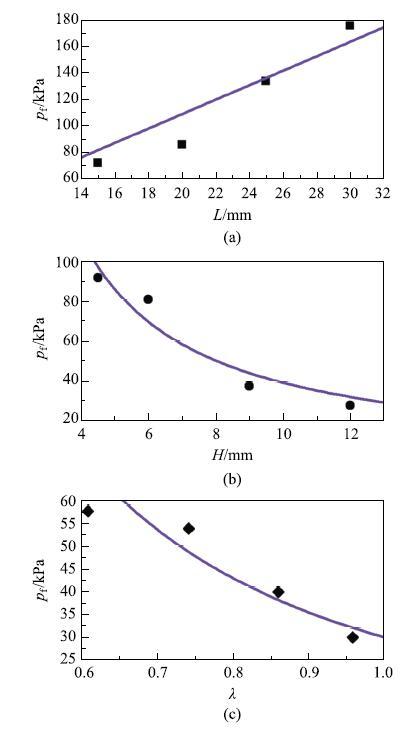
Wang��[48]ϵͳ�����˲��ϲ����ͼ��β������ٽ�й©ѹ����Ӱ��,���β�����Ӱ����ͼ26��ʾ,�ɼ�����Ԥ����ʵ��dz��Ǻ�.˵����ģ���ܽϺ�Ԥ�����й©���ٽ�����,�Ըߵ���������������ṩһ����ָ��.
 ��ʾԭͼ|����ԭͼZIP|����PPT
ͼ26�ٽ�й©ѹ���ͼ��β����Ĺ�ϵ.�ڵ�Ϊʵ����,����Ϊ����Ԥ��[
-->Fig. 26The relations between leak pressures and geometrical parameters. Solid dots are experimental results, purple lines are theoretical predictions[
-->
(2) ����й©.
���ǽ�����й©�ķ�����Ӿ��»��ս��й۲�,����һЩ����й©�ķ������û�з����κ��ƻ�,����ڿ������������ĵط��������ƻ�,���ֶ��������.�������˼�����Ա�ܳ�һ��ʱ�䣺�ڲ���û���ƻ��������,������������δ����ߵ�����Ԫ����й©��?
�ھ����ܷ�����[49]��,�ߵ����ܷ�Ԫ������������Ҫ�ܷ���������֮��,����ѹ��һ����λ��,��ͼ27(a)��ʾ.
 ��ʾԭͼ|����ԭͼZIP|����PPT
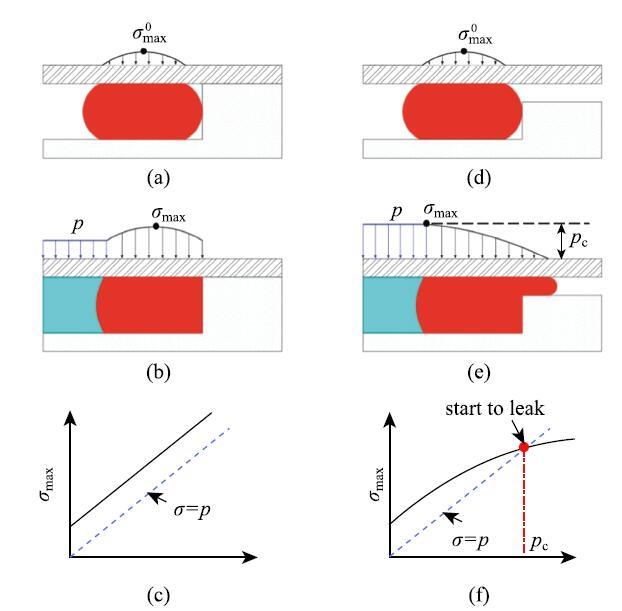
ͼ27(a)$\sim$(c) �����ܷ����ۺ� (d)$\sim$(f) ����й©ԭ��ʾ��ͼ
-->Fig. 27Schematics of (a)$\sim$(c) classical sealing theory and (d)$\sim$(f) elastic leak
-->
�ߵ�����������֮��ĽӴ����Ͻ�����һ���ĽӴ�ѹ���ֲ�,��ʱ�����Ӵ�ѹ����Ϊ$\sigma_{\max }^0 $.������״����,��������������֮��ļ�϶�㹻С,�ߵ���Ԫ����Լ�����ܷ����,���ᱻ����.���ڸߵ���ļ���ģ����С,���ױ���,�����ģ��Զ���ڼ���ģ��,�����ױ�ѹ��.��˵��ܷ�ǻ���ڵ�ѹ������Ϊ$p$ʱ,�൱���ڸߵ�����Χ�����˴�СΪ$p$�ľ�ˮѹ��,��ͼ27(b)��ʾ,���Ӵ�ѹ����Ϊ
\begin{equation} \label{eq20} \sigma _{\max } = \sigma _{\max }^0 + p\tag{20} \end{equation}
ʽ��,$\sigma _{\max }$������ѹ��$p$�Ĺ�ϵ��ͼ27 (c)��ʾ,�ɼ����Ӵ�ѹ����������ѹ��.������״����,�ܷ�ǻ���ڵ�����û�취�����ܷ�Ԫ��������������Ľ����й©.���,��������ѹ�����ӵ����,�����ᷢ��й©.
ʵ����,��������Ľ���治���������Ӵ�,�����һ���ļ�϶,��ͼ27(d)��ʾ.�ڴ�ͳ�ܷ�װ����,����ͨ��������ӹ���������С��϶��,�Ӷ����Ͳ��ϼ���ЧӦ������Ӱ��.����,���ڸߵ���ʯ�ͷ����,���ʼֱ����ҪС�ھ���ֱ���Ա��ڽ���������뾮��Ԥ��λ��.ͬʱ,�����ܷ������ҵ֮ǰ�Ǻ���Ԥ���,�羮�۳ߴ�ı仯��������������.���,���������;��ڼ�ļ�϶�Dz��ɱ����.��Դ�ͳ�ߵ����ܷ�Ԫ��,�����Ѿ��������ܷ�Ԫ���ĽӴ�ѹ���ֲ��Ͳ��ϼ���ЧӦ�ԽӴ�ѹ����Ӱ��[80-82],���ǶԽӴ�ѹ���ı仯��й©֮�����ϵ��ȱ�����������.Liu��[47]ʵʱ�۲��˵���й©����,��ͼ28��ʾ,�������˵���й©�Ļ���,��ͼ27(d)$\sim$ͼ27(f)��ʾ.�ڲ����ǽ���Ħ����𤸽���������,���ߵ��屻Ԥѹ��ʱ,���ڸߵ�������ڽӺ���佨��һ���ĽӴ�ѹ��,��ʱ�����Ӵ�ѹ��Ϊ$\sigma _{\max }^0 $,λ�ڽӴ�����м�λ��.���������ѹ��$p$��ʼ����ʱ,�Ӵ�ѹ��Ҳ����֮����.����,���ڸߵ������һ���ı��οռ�,���ֲ��ϱ������ұ������Ӻ����ļ�϶��,���ϱ��ε��½Ӵ�ѹ�����ӵ��ٶ�С������ѹ���������ٶ�,��ͼ27(f)��ʾ,�����Ӵ�ѹ����λ��������ƶ�.������ѹ�����ӵ��ٽ�ֵ$p_{\rm c}$ʱ,���Ӵ�ѹ����������ѹ��,��λ���ƶ��������.��ʱ�����һС���������Ŷ���������Ͻ���ʱ,�ͻ�����С�ĽӴ�ѹ�������´��������Ӵ����й©.���,��������й©���ٽ�����Ϊ
\begin{equation} \label{eq21} p_{\rm c} = \sigma _{\max }\tag{21} \end{equation}
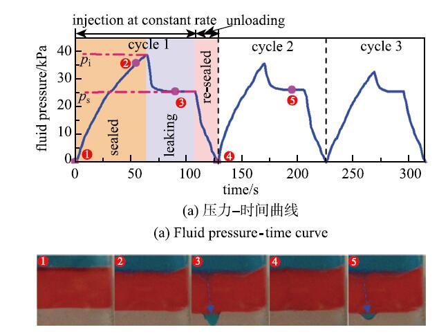
���ڽ���Ħ������𤸽����Ӱ��,����ѹ���ﵽijһ��ֵ$p_{\rm i}$��ʼй©,��ͼ28��ʾ,й©˲������ѹ��Ѹ�ٽ��Ͳ�ά����ƽ̨$p_{\rm s}$.������Ϊй©������̬�κ�,����֮���γ����ȶ�������ͨ��,����Ħ������𤸽����Ӱ����ʧ.��й©�������ܷ�Ԫ����Ȼ��ά�����ٽ�ѹ����,������ģ�����,$p_{\rm s} = p_{\rm c}$. �������ѹ��һ��С��$p_{\rm s}$,й©�ͻ�����ֹͣ.�����¼���ʱ,й©��ֵѹ�����н���,��ƽ̨ѹ��$p_{\rm s}$��������.��˵�����˳�ʼй©ѹ�����ܵ�Ħ������𤸽���ȷǵ������ص�Ӱ��,����̬��,й©�����Ǵ�����,�����.
 ��ʾԭͼ|����ԭͼZIP|����PPT
ͼ28����й©ʵ����
-->Fig. 28Experimental results of elastic leak
-->
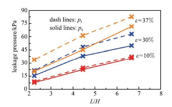
ʵ�鷢��,���ٽ�������һ����Χ�ڲ�������ע���ٶȵ�Ӱ��,ֻ���ܷ�Ԫ���IJ��Ϻͼ��β����й�.���,����й©�������ת��Ϊһ�������Ա�ֵ����,ֻ��Ҫ�Ըߵ�����з���,ͨ���������۵õ����ٽ�����,�Ϳ���ȷ�����ܷ�Ԫ����������й©���ٽ�ѹ��.ʵ�鷢��,�ٽ�ѹ�������ܷ�Ԫ���ij��ȼ�����������,����Ԥѹ��Ӧ������������(ͼ29),�������ܷ�Ԫ���ij��Ȼ�����߳�ʼ�Ӵ�ѹ���Ϳ�������ܷ�Ԫ���ķ������.
 ��ʾԭͼ|����ԭͼZIP|����PPT
ͼ29���β�����й©ѹ����Ӱ��[
-->Fig. 29Effects of geometric parameters on the leak pressure[
-->
2.5 ����й©��Ӧ��
Ϊ����߷�����ķ������,һ��ֱ�۵ķ�����������ߵ���Ԫ���ij���,��֮Ϊ�������.Ȼ��,���ų��ȵ�����,��������佫�������,�ɱ�Ҳ��֮���������.����,�����ķ�������¾���ҵ�б���ס�ķ���Ҳ����������.��2.2������,���������Խϲ�ʱ,������м䲿�ֵĸߵ���ﵽ����ƽ������ʱ������Ÿߵ��峤�ȵ���������������.��һ�ַ����ǽ����ɸ��϶̵ķ��������������,��֮Ϊ�ֲ�ʽ���,��ͼ30(a) ��ʾ. ������������,�ֲ�ʽ��ƿ��Ա�����������е���������.����Ҫ����,������ƿ���ʹ��������ģ�黯.�������Ҫ������Ҫ�����ѹ�����������ߵ���ij���,ʹ�÷������ƺ�������÷dz�����.���ֲ�ʽ��ƿ�������������Ԫ��,ʵ��Ӧ���пɸ�����Ҫ�����ѹ������ѡ�����ķ��������.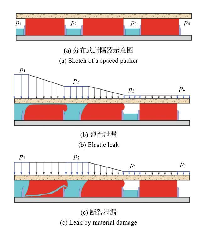 ��ʾԭͼ|����ԭͼZIP|����PPT
ͼ30�ֲ�ʽ������Ĺ���ԭ��
-->Fig. 30Principle of spaced packers
-->
�������������ļ�϶��������ѹ������ʱ(����ˮ),��Ҫ�����ѹ����Ϳ��Լ������ȵķֲ��ڸ����������.�����������,����ڵ���Ԫ���ܳ�һ�������������,�ֲ�ʽ������������ܹ����ܸ����ѹ����,��Ϊ�ڷֲ�ʽ��������и���Ľ���������Լ��������ı���.Ȼ��,ʵ������о���������Ǹ߶ȿ�ѹ����,������Ȼ��������������[83-84],��˼����ڷ����һ��ĸ�ѹ���ܱ����ݵ�����ķ������,ֻ�и�ѹ�˵ĵ�һ�����������ѹ����.����һ��������ƻ���,����ķ����--���Ž���ʧЧ.
Wang��[85]����������õ���й©����߷ֲ�ʽ������ķ������,��ͨ��ʵ���������֤.�����ɸ������ķ������ɳ�ʼ�ܷ��,�����������Ŀ�϶������Һ/�������,��ͼ30(a) ��ʾ.�����һ�����������Һ���Ժ㶨����ע��,Һ��ѹ��$p_{1}$����֮����. �ڳ�ʼ��,Һ��ѹ����Ҫʩ���ڵ�һ���������.��Ϊ�м�Һ/��������Ǹ߶ȿ�ѹ����,��һ��������ĵ�������ζ����強ѹ����ɵ�ѹ���仯���Ժ��Բ���.��������ķ������������й©,����һ����������˵�ѹ���� $p_{1}$-- $p_{2}$�ﵽ�ٽ�ֵ��,��һ��������еĸߵ���;��ڻ��ھֲ�ʧȥ�Ӵ�,�γ�һ����խ��й©ͨ��.���ֵ���й©�����ڸߵ���ĵ��Ա�����ɵ�,û�в����ƻ�,��й©�����з���������������ܱ��ֺ㶨��ѹ����.й©��Һ��ע������������м�Ŀ�϶, $p_{2}$��ʼ����,�ڶ����������ʼ��ѹ���������Ա���,��ͼ30(b) ��ʾ.$p_{1}$ ���� $p_{2}$ ��һ������,ֱ�� $p_{2}$�ﵽijһ�ٽ�ֵ��ʼй©.��������,����и�������������һ��,���ź�����������������,���еķ�����ܹ����ȵijе����ѹ��,�����ص�ѹ���ܺ� $p_{1 }$�ܹ����������ߵ�ˮƽ.
Ȼ��,��������������ʧЧģʽΪ����й©ʱ,�������������߷������.ͬ����й©һ��,�ڳ�ʼ��,Һ��ѹ��$p_{1}$��Ҫʩ���ڵ�һ���������,���ǵ���һ�����������й©��,ѹ���ֲ��͵���й©�е����������ȫ��һ��,��ͼ30(c)��ʾ.���϶��ѻ��γ�������й©ͨ��,��һ������������ټ����е��κ�ѹ����,��$p_{1}=p_{2}$,���е����ѹ��ȫ��ʩ���ڵڶ����������,ֱ���ڶ��������ͬ�����������ƻ�.�����������,�����ж��ٸ������������һ��,���κ�ʱ�̶�ֻ������һ������������ž��ֵ����ѹ��,�������Ӹ�ѹ�������ƻ�,�ﲻ����߷��������Ŀ��.
2.6 �ߵ��������е�ʧ������
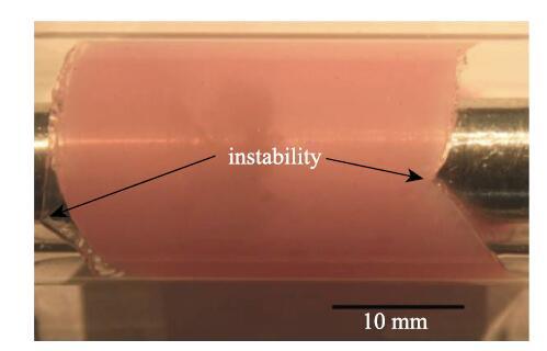
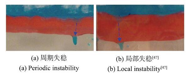
�����������ͻ�����������,����ֶ���ʧ������,�����������塢�ۺۡ�����ָ��ʧ�ȵ�.��Щ��������ѧ�����ѱ��㷺�о�[86-94].���ǹ۲���������ߵ����ʧ������,�����������۽���[88],�Ա���ʧ�ȴ������ֺ�[95-98],�������ÿɿص�ʧ���γ�Ԥ����Ƶĸ���ͼ��,���нṹ������װ������[99-102].���������к���ѹ��������,�ߵ����ܷ�Ԫ��Ҳ����ֶ���ʧ������.Druecke��[46]�۲쵽�ߵ�������Լ������ʱ������Ǿ����α�,�γ���ǰͻ���ļ��(ͼ31).������ѹ����������,�ܷ�Ԫ��Ҳ��������ڻ�ֲ���ʧ��(ͼ32)[47].��Щʧ�Ȼ���ɾֲ������,���ܻ���ٽ�й©ѹ��������ҪӰ��.��ͼ32��ʾ,����й©ͨ������ʧ�ȱ��εļ�˲���.����,��ĿǰΪֹ��û���κ��о�����ʧ�ȶԸߵ���й©��Ӱ��,��Ҫ��δ�����о������Կ���.
 ��ʾԭͼ|����ԭͼZIP|����PPT
ͼ31�ߵ��������������е�ʧ������[
-->Fig. 31Instability formed in the swelling of an elastomeric packer[
-->
 ��ʾԭͼ|����ԭͼZIP|����PPT
ͼ32����й©�е�ʧ������
-->Fig. 32Instability in elastic leak
-->
3 С ��
�������ܷ������������о�����Ҫ����.�ر��Ƕ������ҳ����/������,������и��ÿɿ��ԡ����߷���������ܷ���������֤��ҵ��ȫ,ͬʱ���Ϳ��ɳɱ�����߾���Ч��.����������ˮ��ߵ����������ܷ�ṹ�ı�����ʧЧ��Ϊ�������о���չ,����ˮ��̻������е�Ӧ���ݻ���������ҵ���µ�Ӧ����ˮ���ʧЧģʽ��ʧЧ�о�,�ߵ���������ʵ�鷽����ʧЧģʽ�����͡����Ρ����ѡ�����й©����Ӧ�õ�.�ܵ���˵,ˮ���ܷ���ʷ�ƾ����о���Խϳ��,����ʽ�ߵ����ܷ�����һ���¼������õ���ѧ�����̽������.���֮��,���Ƕ�����ʽ�ߵ���������Ƽ���صĻ��������о��в����,Ӱ��ߵ���������ѧ���ܵĹؼ�������ʧЧ������ȱ��ϵͳ�����������,�����Զ�Խ��Խ������ս�ԵĹ�������ṩ��Ч��ָ��,���кܶ���Ҫ�Ļ���������Ҫ��һ���о�.
��ѧ�ǹ��̿�ѧ,�ڹ����ش����������ս���з����˲��һ�����������ʮ����Ҫ������.ѧ�ƽ�����һ������,��ѧ������ѧ�ƽ�������Ӻܶ�.ϣ��������Ϊ�ٽ���ѧ������ѧ�ƵĽ����ṩ�ο�.
The authors have declared that no competing interests exist.
�ο����� ԭ��˳��
������ȵ���
������������
�����ڿ�Ӱ������
| [1] | . |
| [2] | . |
| [3] | . |
| [4] | . |
| [5] | . |
| [6] | . ˮƽ��ѹ�Ѽ����Ѿ���Ϊ�������������ء�ҳ�����غ����������ȷdz��������صĹؼ�����.������ɢ�ѷ�ģ��,���ѷ���м�,�����˶�ά���ѹ��ˮƽ���������ѷ���ֵ�Ծ�ģ��,��������Ԫ�������ģ��,��ö��ѹ��ˮƽ���Ծ��������ߺ�ѹ��������.��������:���ѹ��ˮƽ�����Ծ���������һ����Ϊ7����:��Ͳ����Ρ��ѷ��������Ρ��ѷ�C�ز�˫�������Ρ��ѷ���ŶΡ��ز��������Ρ�ϵͳ�������κͱ߽����ö�,�����ѷ�C�ز�˫�������κ��ѷ���Ŷ������������.�������ѷ��������ѷ��ࡢ�ѷ첻�Գơ��ѷ첻�ȳ����ѷ첿��ȱʧ�����ض��Ծ��������ߵ�Ӱ��,�������:�ѷ��������ѷ�����Ծ��������ߵ�Ӱ�����.�϶���ѷ졢�ϴ��ѷ��ࡢ�ԳƵ��ѷ�͵ȳ����ѷ������ڽ���ѹ��ˮƽ��������������,��߲���.����������ֵ�Ծ�ģ��Ӧ�����Ĵ����һ�ڶ��ѹ��ˮƽ����ѹ���ָ����Ե���ֵ�Ծ�����,�������:���Ľ�����ģ�Ϳ��ԽϺõ����ѹ���ָ���������,���Ի���ѷ�ĵ����������ѷ쳤��,Ϊѹ��Ч�����ۺ�ѹ������ṩָ��. . ˮƽ��ѹ�Ѽ����Ѿ���Ϊ�������������ء�ҳ�����غ����������ȷdz��������صĹؼ�����.������ɢ�ѷ�ģ��,���ѷ���м�,�����˶�ά���ѹ��ˮƽ���������ѷ���ֵ�Ծ�ģ��,��������Ԫ�������ģ��,��ö��ѹ��ˮƽ���Ծ��������ߺ�ѹ��������.��������:���ѹ��ˮƽ�����Ծ���������һ����Ϊ7����:��Ͳ����Ρ��ѷ��������Ρ��ѷ�C�ز�˫�������Ρ��ѷ���ŶΡ��ز��������Ρ�ϵͳ�������κͱ߽����ö�,�����ѷ�C�ز�˫�������κ��ѷ���Ŷ������������.�������ѷ��������ѷ��ࡢ�ѷ첻�Գơ��ѷ첻�ȳ����ѷ첿��ȱʧ�����ض��Ծ��������ߵ�Ӱ��,�������:�ѷ��������ѷ�����Ծ��������ߵ�Ӱ�����.�϶���ѷ졢�ϴ��ѷ��ࡢ�ԳƵ��ѷ�͵ȳ����ѷ������ڽ���ѹ��ˮƽ��������������,��߲���.����������ֵ�Ծ�ģ��Ӧ�����Ĵ����һ�ڶ��ѹ��ˮƽ����ѹ���ָ����Ե���ֵ�Ծ�����,�������:���Ľ�����ģ�Ϳ��ԽϺõ����ѹ���ָ���������,���Ի���ѷ�ĵ����������ѷ쳤��,Ϊѹ��Ч�����ۺ�ѹ������ṩָ��. |
| [7] | . ��ʶ˫�ض��������ˮ���������������ǻش��γ�ʲô���͵���϶���������Ͳز����ʵĹؼ�. ��϶�ķֲ�������߶���ʵľ�������,�����ڻ��ʿ�϶�е��������,��϶�Ĵ��ڻ����������оֲ�����ѹ���������ı仯,���¾ֲ���������϶����Ϊ��,�������ִ�������,��������Ч��. ���Ļ��ڿ�����϶˫������ģ��,����������趨����ƽ�еȳ��Ҿ���һ���������϶,������϶����Լ��(��϶֮�����/��������)����϶��Գ���(��϶����/��������)����������������Ӱ��. �������������϶��Գ��ȵ�����,��������Ч������,������������е���ˮ������ˮ���ͶȺ͵���������,��ˮ����Ĺ�����Χ��С������;������϶֮����Լ������,��ΧԽ��Խ��Ļ��ʿ�Ѩ���ѹ�����С,��ë��ѹ����������,�������ƹ���Щ����,������ˮ������. . ��ʶ˫�ض��������ˮ���������������ǻش��γ�ʲô���͵���϶���������Ͳز����ʵĹؼ�. ��϶�ķֲ�������߶���ʵľ�������,�����ڻ��ʿ�϶�е��������,��϶�Ĵ��ڻ����������оֲ�����ѹ���������ı仯,���¾ֲ���������϶����Ϊ��,�������ִ�������,��������Ч��. ���Ļ��ڿ�����϶˫������ģ��,����������趨����ƽ�еȳ��Ҿ���һ���������϶,������϶����Լ��(��϶֮�����/��������)����϶��Գ���(��϶����/��������)����������������Ӱ��. �������������϶��Գ��ȵ�����,��������Ч������,������������е���ˮ������ˮ���ͶȺ͵���������,��ˮ����Ĺ�����Χ��С������;������϶֮����Լ������,��ΧԽ��Խ��Ļ��ʿ�Ѩ���ѹ�����С,��ë��ѹ����������,�������ƹ���Щ����,������ˮ������. |
| [8] | . In this work, we report the successful development of a cement–rubber reactive composite with reversible mechanical properties. Initially, the composite behaves like rubber containing inert filler, but when exposed to water, it increases in volume and reaches a stiffness that is intermediate between that of hydrogenated nitrile butadiene rubber (HNBR) and hydrated cement, while maintaining a relatively large ductility characteristic of rubber. After drying, the modulus increases even further up to 400 MPa. Wet/drying cycles prove that the elastic modulus can reversibly change between 150 and 400 MPa. Utilizing attenuated total reflection Fourier transform infrared spectroscopy), we demonstrate that the high pH produced by the hydration of cement triggers the hydrolysis of the rubber nitrile groups into carboxylate anions. Thus, the salt bridges, generated between the carboxylate anions of the elastomer and the cations of the filler, are responsible for the reversible variations in volume and elastic modul... |
| [9] | . |
| [10] | |
| [11] | . |
| [12] | . Not Available |
| [13] | . |
| [14] | . ҳ������ָ�����ڸ����л�����ҳ����������������״̬Ϊ��Ҫ���ڷ�ʽ����Ȼ��,�й���Դ���ḻ,����ֲ��㷺.ҳ���������ܻ����ҹ����������������㡢ú��ʯȼ��������Ⱦ������,�ѳ�Ϊ�й���ɫ��Դ��������Ҫ����.���ܱ���ҳ����"����"ȡ���˳ɹ�,ĿǰҲ����Ԥ�ڲ���5%��15%�IJ�����.�뱱���������,�й�ҳ���������,����������,��Ȼ��ȵ�,���,��Ч�������ٸ�������Ѻ���ս.������,Χ�ƹ����ش���Դս������,��������չǰ��,ѧ�����ҵ�����϶�ҳ������Ч���ɵĹؼ���ѧ�ͼ�������չ���о�.���Ľ�Ͻ������Ĵ������������ҳ������������������������,����й�δ��3500 m��������ɵ�����ս,����ʳ������ѷ췢�����첻ͬ���ϸ�ѹ�����ӡ�ˮƽӦ�����仯��������,���ܺ��ܽ���Ŀǰ�й�ҳ������Ч�������ٵ���ѧ��ѧ����,��Ҫ������������µİ�ȫ�������꾮��ѧ���ۺͷ�����ˮ��ѹ���������Ͷ�߶ȷ����γɻ��ơ���߶�������ѧ�����������������."�ҳ������Ч����"���о���������ش���Դ����,��ѧ�����ش�,���̱�����ȷ,��Ҫ������ѧ��ʯ���̡�������������ѧ���̺ͻ������̵ȶ�ѧ��ר�Һ���,��չ�����о�������ģ�⡢��ֵģ�⼰�ֳ�������ۺ�Ӧ�û����о�,ȡ�ø�Ч����ҳ�����������뼼����ͻ��.ѧ�ƽ������о�ҳ������Ч�������⡢ͻ�Ƽ���ƿ��������,ֻ����ѧ��ʯ���̡������ѧ��ѧ��ʵ����Ƚ����ں�,���ܸ�����Ч���ƶ�ҳ�������ȷdz���������Դ�Ŀ���. . ҳ������ָ�����ڸ����л�����ҳ����������������״̬Ϊ��Ҫ���ڷ�ʽ����Ȼ��,�й���Դ���ḻ,����ֲ��㷺.ҳ���������ܻ����ҹ����������������㡢ú��ʯȼ��������Ⱦ������,�ѳ�Ϊ�й���ɫ��Դ��������Ҫ����.���ܱ���ҳ����"����"ȡ���˳ɹ�,ĿǰҲ����Ԥ�ڲ���5%��15%�IJ�����.�뱱���������,�й�ҳ���������,����������,��Ȼ��ȵ�,���,��Ч�������ٸ�������Ѻ���ս.������,Χ�ƹ����ش���Դս������,��������չǰ��,ѧ�����ҵ�����϶�ҳ������Ч���ɵĹؼ���ѧ�ͼ�������չ���о�.���Ľ�Ͻ������Ĵ������������ҳ������������������������,����й�δ��3500 m��������ɵ�����ս,����ʳ������ѷ췢�����첻ͬ���ϸ�ѹ�����ӡ�ˮƽӦ�����仯��������,���ܺ��ܽ���Ŀǰ�й�ҳ������Ч�������ٵ���ѧ��ѧ����,��Ҫ������������µİ�ȫ�������꾮��ѧ���ۺͷ�����ˮ��ѹ���������Ͷ�߶ȷ����γɻ��ơ���߶�������ѧ�����������������."�ҳ������Ч����"���о���������ش���Դ����,��ѧ�����ش�,���̱�����ȷ,��Ҫ������ѧ��ʯ���̡�������������ѧ���̺ͻ������̵ȶ�ѧ��ר�Һ���,��չ�����о�������ģ�⡢��ֵģ�⼰�ֳ�������ۺ�Ӧ�û����о�,ȡ�ø�Ч����ҳ�����������뼼����ͻ��.ѧ�ƽ������о�ҳ������Ч�������⡢ͻ�Ƽ���ƿ��������,ֻ����ѧ��ʯ���̡������ѧ��ѧ��ʵ����Ƚ����ں�,���ܸ�����Ч���ƶ�ҳ�������ȷdz���������Դ�Ŀ���. |
| [15] | |
| [16] | . |
| [17] | . Two types of mechanisms could lead to loss of cement-sheath integrity: mechanical and chemical degradations. However, chemical degradation by CO2 does not seem to be a real threat when the cement sheath is initially without default. Hence, it is important to understand the mechanical mechanisms that could lead to loss of cement-sheath integrity before and during CO2 sequestration. This is with this objective that Total has developed an integrated perspective whereby all events in the life of the well, are scrutinized. The description of this perspective is the objective of this paper. |
| [18] | . |
| [19] | . Horizontal drilling and hydraulic fracturing are transforming energy production, but their potential environmental effects remain controversial. We analyzed 141 drinking water wells across the Appalachian Plateaus physiographic province of northeastern Pennsylvania, examining natural gas concentrations and isotopic signatures with proximity to shale gas wells. Methane was detected in 82% of drinking water samples, with average concentrations six times higher for homes <1 km from natural gas wells (P = 0.0006). Ethane was 23 times higher in homes <1 km from gas wells (P = 0.0013); propane was detected in 10 water wells, all within approximately 1 km distance (P = 0.01). Of three factors previously proposed to influence gas concentrations in shallow groundwater (distances to gas wells, valley bottoms, and the Appalachian Structural Front, a proxy for tectonic deformation), distance to gas wells was highly significant for methane concentrations (P = 0.007; multiple regression), whereas distances to valley bottoms and the Appalachian Structural Front were not significant (P = 0.27 and P = 0.11, respectively). Distance to gas wells was also the most significant factor for Pearson and Spearman correlation analyses (P < 0.01). For ethane concentrations, distance to gas wells was the only statistically significant factor (P < 0.005). Isotopic signatures (delta C-13-CH4, delta C-13-C2H6, and delta H-2-CH4), hydrocarbon ratios (methane to ethane and propane), and the ratio of the noble gas He-4 to CH4 in groundwater were characteristic of a thermally postmature Marcellus-like source in some cases. Overall, our data suggest that some homeowners living < 1 km from gas wells have drinking water contaminated with stray gases. |
| [20] | |
| [21] | . |
| [22] | . |
| [23] | . his paper introduces a predictive model for the stress and pressure evolutions in a wellbore cement liner at early ages. A pressure state equation is derived that observes the coupling of the elastic changes of the solid matrix, the eigenstress developments in the solid and porespaces, and the mass consumption of water in course of the reaction. Here, the transient constitution of the solid volume necessitates advancing the mechanical state of the poroelastic cement skeleton incrementally and at constant hydration degree. Next, analytic function theory is employed to assess the localization of stresses along the steel�Ccement (SC) and rock�Ccement (RC) interfaces by placing the casing eccentrically with respect to the wellbore hole. Though the energy release rate due to complete debonding of either interface is only marginally influenced by the eccentricity, the risk of evolving a microcrack along the thick portion of the sheath is substantially increased. Additionally, it is observed that the risk of microannulus formation is principally affected by the pressure rebound, which is engendered by the slowing reaction rate and amplified for rock boundaries with low permeability. |
| [24] | . There is an ongoing debate, in Concrete Science and Engineering, whether cementitious materials can be viewed as poromechanics materials in the sense of the porous media theory. The reason for this debate is that a main part of the porosity of these materials manifests itself at a scale where the water phase cannot be considered as a bulk water phase, but as structural water; in constrast to water in the gel porosity and the capillary porosity. The focus of this paper is two-fold: (1) to review the microstructure of cementitious materials in the light of microporomechanics theory by starting at the scale where physical chemistry meets mechanics, and which became recently accessible to mechanical testing (nanoindentation):(2) to provide estimates of the poroelastic properties (drained and undrained stiffness, Biot coefficient, Biot modulus, Skempton coefficient) of cementitious materials (cement paste, mortar and concrete) by means of advanced homogenization techniques of microporomechanics. This combined experimental-theoretical microporomechanics approach allows us to deliver a blueprint of the elementary poroelastic properties of all cementitious materials, which do not change from one cementitious material to another, but which are intrinsic properties. These properties result from the intrinsic gel porosity of low density and high density C-S-H, which yield a base Biot coefficient of 0.61< b 810.71 and a Skempton coefficient of B =0.20�C0.25. While the base Biot coefficient decreases gradually at larger scales, because of the addition of non-porous solid phases (Portlandite,..., aggregates), it is shown that the Skempton coefficient is almost constant over 3�C5 orders of magnitude. |
| [25] | . Abstract The risk of early-age fracture of cementitious materials in ever more challenging environments provides a unique opportunity to employ an experimental chemo-mechanical platform to develop functional relations between hydration degree, fracture and strength properties, assessed by isothermal calorimetry, micro-scratching, splitting and microindentation on white cement paste at various curing ages from 7 h to 28 days. We show that the modulus, tensile strength, fracture toughness and energy all evolve with a natural logarithmic dependence on the hydration degree. These trends are linked to the densification of the material during the hydration process, explained by compaction mechanics and free volume theory. We show that while the fracture process zone size is essentially constant during the hydration process, the ductility of the material, quantified by M/H, decreases, and is consistent with the evolution of Kc/H. Both quantities provide a convenient way to experimentally assess the fracture sensitivity of early-age cement-based materials. |
| [26] | . The poromechanical behaviour of hardened cement paste under isotropic loading is studied on the basis of an experimental testing program of drained, undrained and unjacketed compression tests. The macroscopic behaviour of the material is described in the framework of the mechanics of porous media. The poroelastic parameters of the material are determined and the effect of stress and pore pressure on them is evaluated. Appropriate effective stress laws which control the evolution of total volume, pore volume, solid volume, porosity and drained bulk modulus are discussed. A phenomenon of degradation of elastic properties is observed in the test results. The microscopic observations showed that this degradation is caused by the microcracking of the material under isotropic loading. The good compatibility and the consistency of the obtained poromechanical parameters demonstrate that the behaviour of the hardened cement paste can be indeed described within the framework of the theory of porous media. |
| [27] | |
| [28] | . Despite its ubiquitous presence as binding phase in all cementitious materials, the mechanical behavior of calcium-silicate-hydrates (C-S-H) is still an enigma that has deceived many decoding attempts from experimental and theoretical sides. In this paper, we propose and validate a new technique and experimental protocol to rationally assess the nanomechanical behavior of C-S-H based on a statistical analysis of hundreds of nanoindentation tests. By means of this grid indentation technique we identify in situ two structurally distinct but compositionally similar C-S-H phases heretofore hypothesized to exist as low density (LD) C-S-H and high density (HD) C-S-H, or outer and inner products. The main finding of this paper is that both phases exhibit a unique nanogranular behavior which is driven by particle-to-particle contact forces rather than by mineral properties. We argue that this nanomechanical blueprint of material invariant behavior of C-S-H is a consequence of the hydration reactions during which precipitating C-S-H nanoparticles percolate generating contact surfaces. As hydration proceeds, these nanoparticles pack closer to center on-average around two characteristic limit packing densities, the random packing limit (eta=64%) and the ordered face-centered cubic (fcc) or hexagonal close-packed (hcp) packing limit (eta=74%), forming a characteristic LD C-S-H and HD C-S-H phase. [All rights reserved Elsevier] |
| [29] | . |
| [30] | . Abstract Little understanding exists between the early-age stress developments in a wellbore cement sheath and its risk of impairment. During hydration, the cement morphology and pore-pressure changes induce eigenstresses in the solid and pore volumes. Utilizing these stresses as the driving mechanism of fracture, this paper formalizes the inspection of a radial crack in an elastic cement sheath constrained by an inner steel casing and an outer rock formation. The solution is constructed in the framework of analytic function theory and seeks the Green’s function for an edge dislocation in the intermediate cement phase. A dislocation pile-up along the line of fracture constructs a singular integral equation for the crack opening displacement derivative, from which the energy release rate is readily deduced. Under the uniform development of eigenstresses, the stiffness ratios of steel-to-cement and rock-to-cement generally predict the crack to initiate along the steel-cement interface. Here, the impacts of (i) a rigid bond and (ii) a sliding interface with no shear are assessed. This leads to the primary result of the paper: the potential for radial fracture is substantially mitigated by ensuring the shear connection between the steel casing and the cement sheath. |
| [31] | |
| [32] | . |
| [33] | . Using the heavy oils obtained from Liaohe oilfields in China, we have conducted the aquathermolysis reaction in laboratory at 240 degree C. The results showed that Liaohe heavy oils have been undergoing visbreaking in the process of steam-drive and steam stimulation. After reaction with steam, the viscosity of the heavy oil was reduced by 28-42 % and the amount of the saturated and aromatic hydrocarbons increased, while resin and asphaltene decreased. The gas partition chromatography showed that the accumulated amount of carbon numbers increased, after reaction, the accumulated amount of carbon numbers less than C//2//0 are 38.79-53.92 % , and before reaction they are 13.30-20.92 % . The results provided the basic data for heavy oil recovery by in situ catalytic method in production of heavy oil in oilfields. |
| [34] | . |
| [35] | . Loss of zonal isolation in a wellbore can be caused by mechanical failure ofthe cement or by development of a microannulus. However, behavior of thesealant is driven by specific boundary conditions such as rock properties.Large-scale laboratory testing of the cement sheath in an annular geometry anda confined situation was performed to simulate various downhole stressconditions and evaluate the behavior of several sealants. Failure modes of thecement sheath were determined as a function of cement mechanical properties,loading parameters, and boundary conditions. Results were used to validate ananalytical model that predicts cement-sheath failure. |
| [36] | . |
| [37] | . After a well has been drilled, the drilling fluid should be removed and replaced with either cement and/or completion fluids. For effective zonal isolation and optimum hydrocarbon production during the life of the well, the entire drilling fluid should be removed from the annulus. Cement and completion fluids are sensitive to drilling fluid contamination, and even a thin layer of oil-based drilling fluid could prevent the cement from bonding to the formation and the casing. In addition, for optimum hydrocarbon production, the cement sheath must be able to withstand the stresses throughout the life of the well. |
| [38] | . Recent advances in scratch test analysis provide new ways to relate measured scratch test properties not only to strength properties but fracture properties of materials as well. Herein, we present an application of such tools to oil well cements cured at high temperatures and pressures. We find a concurrent increase of strength and toughness of different oil well cement baseline formulations which we relate to the water-to-binder ratio for a series of cementitious materials prepared with cement and silica flour. The scratch test thus emerges as a self-consistent technique for both cohesive�Cfrictional strength and fracture properties that is highly reproducible, almost non-destructive, and not more sophisticated than classical compression tests, which makes this ��old�� test highly attractive for performance-based field applications. |
| [39] | . |
| [40] | . This chapter describes the mixed mode cracking in layered materials. There is ample experimental evidence that cracks in brittle, isotropic, homogeneous materials propagate such that pure mode I conditions are maintained at the crack tip. An unloaded crack subsequently subject to a combination of modes I and II will initiate growth by kinking in such a direction that the advancing tip is in mode I. The chapter also elaborates some of the basic results on the characterization of crack tip fields and on the specification of interface toughness. The competition between crack advance within the interface and kinking out of the interface depends on the relative toughness of the interface to that of the adjoining material. The interface stress intensity factors play precisely the same role as their counterparts in elastic fracture mechanics for homogeneous, isotropic solids. When an interface between a bimaterial system is actually a very thin layer of a third phase, the details of the cracking morphology in the thin interface layer can also play a role in determining the mixed mode toughness. The elasticity solutions for cracks in multilayers are also elaborated. |
| [41] | . |
| [42] | |
| [43] | |
| [44] | |
| [45] | |
| [46] | . Experiments were performed to visualize,in situ, the deformation and leakage of soft seals under differential pressure. Two annular seals and a flat, rectangular seal were investigated in the experiments. The observations show that large, nonuniform elastic deformation precedes seal leakage. A corresponding finite element model for a rectangular solid seal shows that large deformation leads to a decrease in the compressive sealing stress between the seal and the surface against which it seals. The predicted flow path for the model is qualitatively similar to the flow path observed in the experiments. A leakage mechanism in which nonuniform elastic deformation leads to seal leakage is proposed. |
| [47] | . Abstract An elastomeric seal may leak by elastic deformation without any material damage. We describe elastic leak using a theoretical model, and watch a seal deform and leak using a transparent experimental setup. The elastomer seals the fluid by forming contact with surrounding hard materials. As the fluid pressure increases, the contact stress also increases but not as much. When the fluid pressure surpasses the contact stress, the elastomer and the hard materials lose contact in some region, forming a leaking path. The critical fluid pressure for elastic leak depends on the geometry and constraint of the seal, but is insensitive to the rate at which the fluid is injected. Our study points to the significance of elastic deformation in modes of failure that also involve material damage. |
| [48] | . Elastomeric seals are essential to two great technological advances in oilfields: horizontal drilling and hydraulic fracturing. This paper describes a method to study elastomeric seals by using the pressure-extrusion curve (i.e., the relation between the drop of pressure across a seal and the volume of extrusion of the elastomer). Emphasis is placed on a common mode of failure found in oilfields: leak caused by a crack across the length of a long seal. We obtain an analytical solution of large elastic deformation, which is analogous to the Poiseuille flow of viscous liquids. We further obtain analytical expressions for the energy release rate of a crack and the critical pressure for the onset of its propagation. The theory predicts the pressure-extrusion curve using material parameters (elastic modulus, sliding stress, and fracture energy) and geometric parameters (thickness, length, and precompression). We fabricate seals of various parameters in transparent chambers on a desktop, and watch the seals extrude, slide, rupture and leak. The experimentally measured pressure-extrusion curves agree with theoretical predictions remarkably well. © 2016 Elsevier Ltd |
| [49] | |
| [50] | . We develop a method of poroelastic relaxation indentation (PRI) to characterize thin layers of gels. The solution to the time-dependent boundary-value problem is obtained in a remarkably simple form, so that the force-relaxation curve obtained by indenting a gel readily determines all the poroelastic constants of the gel��the shear modulus, Poisson��s ratio, and the effective diffusivity. The method is demonstrated with a layer of polydimethylsiloxane immersed in heptane. |
| [51] | . An elastomeric gel is a mixture of a polymer network and a solvent. In response to changes in mechanical forces and in the chemical potential of the solvent in the environment, the gel evolves by two concurrent molecular processes: the conformational change of the network, and the migration of the solvent. The two processes result in viscoelasticity and poroelasticity, and are characterized by two material-specific properties: the time of viscoelastic relaxation and the effective diffusivity of the solvent through the network. The two properties define a material-specific length. The material-specific time and length enable us to discuss macroscopic observations made over different lengths and times, and identify limiting conditions in which viscoelastic and poroelastic relaxations have either completed or yet started. We formulate a model of homogeneous deformation, and use several examples to illustrate viscoelasticity-limited solvent migration, where the migration of the solvent is pronounced, but the size of the gel is so small that the rate of change is limited by viscoelasticity. We further describe a theory that evolves a gel through inhomogeneous states. Both infinitesimal and finite deformation are considered. |
| [52] | . A large quantity of small molecules may migrate into a network of long polymers, causing the network to swell, forming an aggregate known as a polymeric gel. This paper formulates a theory of the coupled mass transport and large deformation. The free energy of the gel results from two molecular processes: stretching the network and mixing the network with the small molecules. Both the small molecules and the long polymers are taken to be incompressible, a constraint that we enforce by using a Lagrange multiplier, which coincides with the osmosis pressure or the swelling stress. The gel can undergo large deformation of two modes. The first mode results from the fast process of local rearrangement of molecules, allowing the gel to change shape but not volume. The second mode results from the slow process of long-range migration of the small molecules, allowing the gel to change both shape and volume. We assume that the local rearrangement is instantaneous, and model the long-range migration by assuming that the small molecules diffuse inside the gel. The theory is illustrated with a layer of a gel constrained in its plane and subject to a weight in the normal direction. We also predict the scaling behavior of a gel under a conical indenter. |
| [53] | . An elastomeric gel is a cross-linked polymer network swollen with a solvent (fluid). A continuum-mechanical theory to describe the various coupled aspects of fluid permeation and large deformations (e.g., swelling and squeezing) of elastomeric gels is formulated. The basic mechanical force balance laws and the balance law for the fluid content are reviewed, and the constitutive theory that we develop is consistent with modern treatments of continuum thermodynamics, and material frame-indifference. In discussing special constitutive equations we limit our attention to isotropic materials, and consider a model for the free energy based on a Flory�CHuggins model for the free energy change due to mixing of the fluid with the polymer network, coupled with a non-Gaussian statistical�Cmechanical model for the change in configurational entropy��a model which accounts for the limited extensibility of polymer chains. As representative examples of application of the theory, we study (a) three-dimensional swelling-equilibrium of an elastomeric gel in an unconstrained, stress-free state; and (b) the following one-dimensional transient problems: (i) free-swelling of a gel; (ii) consolidation of an already swollen gel; and (iii) pressure-difference-driven diffusion of organic solvents across elastomeric membranes. |
| [54] | . We present a theory for the behavior of a solid undergoing two interdependent processes, a macroscopic or mechanical process due to the deformation of the solid and a microscopic or chemical process due to the migration of a chemical species through the solid. The principle of virtual power is invoked to deduce the basic balances of the theory, namely the mechanical force balance and the transport balance for the chemical species. In combination with thermodynamically consistent constitutive relations, these balances generate the basic equations of the theory. Keeping in mind applications involving the swelling of polymer networks by liquids, a specialization of the theory is presented and applied to study the influences of mechanical and chemical interactions on equilibrium states and diffusive dynamical processes. It is shown that the possibility of a mechanically induced phase transition is governed by two parameters: the Flory interaction parameter and a parameter given by the product between the number of cross-linked units per unit reference volume and the molecular volume of the liquid molecule. As for diffusion, it is shown that the theory is able to describe the pressure-induced diffusion in swollen membranes. |
| [55] | . Hydrogels possess magnificent properties which may be harnessed for novel applications. However, this is not achievable if the mechanical behaviors of hydrogels are not well understood. This paper aims to provide the reader with a bird's eye view of the mechanics of hydrogels, in particular the theories associated with deformation of hydrogels, the phenomena that are commonly observed, and recent developments in applications of hydrogels. Besides theoretical analyses and experimental observations, another feature of this paper is to provide an overview of how mechanics can be applied. |
| [56] | |
| [57] | . A model is proposed for the structure of a cross�\linked network, such as exists in a vulcanized rubber, which is amenable to statistical treatment. Expressions are derived for the structural entropy of the network, and for the entropy change on deformation. The latter is in agreement with the relationship derived by Wall and others by a different treatment. |
| [58] | |
| [59] | . |
| [60] | . It is postulated that (A) the material is isotropic, (B) the volume change and hysteresis are negligible, and (C) the shear is proportional to the traction in simple shear in a plane previously deformed, if at all, only by uniform dilatation or contraction. It is deduced that the general strain�\energy function,W, has the formW=G4��i=13(��i611��i)2+H4��t=13(��i2611��i2),where the ��i's are the principal stretches (1+principal extension),Gis the modulus of rigidity, andHis a new elastic constant not found in previous theories. The differences between the principal stresses are ��i[minus]��i=��i68W/68��i[minus]��i68W/68��i. Calculated forces agree closely with experimental data on soft rubber from 400 percent elongation to 50 percent compression. |
| [61] | The mathematical theory of small elastic deformations has been developed to a high degree of sophistication on certain fundamental assumptions regarding the stress-strain relationships which are obeyed by the materials considered. The relationships taken are, in effect, a generalization of Hooke��s law�� ut tensio , sic vis . The justification for these assumptions lies in the widespread agreement of experiment with the predictions of the theory and in the interpretation of the elastic behaviour of the materials in terms of their known structure. The same factors have contributed to our appreciation of the limitations of these assumptions. |
| [62] | Many attempts have been made to reproduce theoretically the stress-strain curves obtained from experiments on the isothermal deformation of highly elastic 'rubberlike' materials. The existence of a strain-energy function has usually been postulated, and the simplifications appropriate to the assumptions of isotropy and incompressibility have been exploited. However, the usual practice of writing the strain energy as a function of two independent strain invariants has, in general, the effect of complicating the associated mathematical analysis (this is particularly evident in relation to the calculation of instantaneous moduli of elasticity) and, consequently, the basic elegance and simplicity of isotropic elasticity is sacrificed. Furthermore, recently proposed special forms of the strain-energy function are rather complicated functions of two invariants. The purpose of this paper is, while making full use of the inherent simplicity of isotropic elasticity, to construct a strain-energy function which: (i) provides an adequate representation of the mechanical response of rubberlike solids, and (ii) is simple enough to be amenable to mathematical analysis. A strain-energy function which is a linear combination of strain invariants defined by �� (��)=(a1��+a2��+a3��-3)/�� is proposed; and the principal stretches a1,a2 and a3 are used as independent variables subject to the incompressibility constraint a1a2a3=1. Principal axes techniques are used where appropriate. An excellent agreement between this theory and the experimental data from simple tension, pure shear and equibiaxial tension tests is demonstrated. It is also shown that the present theory has certain repercussions in respect of the constitutive inequality proposed by Hill (1968a, 1970b). |
| [63] | . Aconstitutive model is proposed for the deformation of rubber materials which is shown to represent successfully the response of these materials in uniaxial extension, biaxial extension, uniaxial compression, plane strain compression and pure shear. The developed constitutive relation is based on an eight chain representation of the underlying macromolecular network structure of the rubber and the non-Gaussian behavior of the individual chains in the proposed network. The eight chain model accurately captures the cooperative nature of network deformation while requiring only two material parameters, an initial modulus and a limiting chain extensibility. Since these two parameters are mechanistically linked to the physics of molecular chain orientation involved in the deformation of rubber, the proposed model represents a simple and accurate constitutive model of rubber deformation. The chain extension in this network model reduces to a function of the root-mean-square of the principal applied stretches as a result of effectively sampling eight orientations of principal stretch space. The results of the proposed eight chain model as well as those of several prominent models are compared with experimental data of Treloar (1944, Trans. Faraday Soc. 40, 59) illustrating the superiority, simplicity and predictive ability of the proposed model. Additionally, a new set of experiments which captures the state of deformation dependence of rubber is described and conducted on three rubber materials. The eight chain model is found to model and predict accurately the behavior of the three tested materials further confirming its superiority and effectiveness over earlier models. |
| [64] | |
| [65] | . Soft materials including elastomers and gels are widely used in applications of energy absorption, soft robotics, bioengineering, and medical instruments. For many soft materials subject to loading and unloading cycles, the stress required on reloading is often less than that on the initial loading, known as Mullins effect. Meanwhile, soft materials usually exhibit rate-dependent viscous behavior. Both effects were recently reported on a new kind of synthesized tough gel, with capability of large deformation, high strength, and extremely high toughness. In this work, we develop a coupled viscoelastic and Mullins-effect model to characterize the deformation behavior of the tough gel. We modify one of the elastic components in Zener model to be a damageable spring to incorporate the Mullins effect and model the viscous effect to behave as a Newtonian fluid. We synthesized the tough gel described in the literature (Sun et al., Nature 2012) and conducted uniaxial tensile tests and stress relaxation tests. We also investigated the two effects on three other soft materials, polyacrylate elastomer, Nitrile-Butadiene Rubber, and polyurethane. We find that our presented model is so robust that it can characterize all the four materials, with modulus ranging from a few tens of kilopascal to megapascal. The theory and experiment for all tested materials agree very well. Copyright © 2017 by ASME. |
| [66] | . |
| [67] | . Scitation is the online home of leading journals and conference proceedings from AIP Publishing and AIP Member Societies |
| [68] | . Scitation is the online home of leading journals and conference proceedings from AIP Publishing and AIP Member Societies |
| [69] | . |
| [70] | . Swellable elastomers are used to seal flow channels in oilfield operations. After sealing, the elastomers are constrained triaxially, and a contact load builds up between the elastomers and surrounding rigid materials. For these applications, the ability to predict the evolution of the contact load is important. This work introduces an experimental setup to measure the contact load as a function of time. The experimental data are well represented by a simple time-relaxation equation derived from the linear poroelastic theory, enabling a determination of the effective diffusivity of solvent inside the elastomers. |
| [71] | . A network of polymers can imbibe a large quantity of a solvent and swell, resulting in a gel. The swelling process can be markedly influenced by a mechanical load and geometric constraint. When the network, solvent, and mechanical load equilibrate, inside the gel the chemical potential of the solvent is homogeneous, but the concentration of the solvent and the deformation of the network can be inhomogeneous. We use the chemical potential of the solvent and the deformation gradient of the network as the independent variables of the free-energy function, and show that the boundary value problem of the swollen gel is equivalent to that of a hyperelastic solid. We implement this approach in the finite-element package, ABAQUS, and analyze examples of swelling-induced deformation, contact, and bifurcation. Because commercial software like ABAQUS is widely available, this work may provide a powerful tool to study complex phenomena in gels. |
| [72] | . A polymer network can imbibe water from environment and swell to an equilibrium state. If the equilibrium is reached when the network is subject to external mechanical constraint, the deformation of the network is typically anisotropic and the concentration of water inhomogeneous. Such an equilibrium state in a network constrained by a hard core is modeled here with a nonlinear differential equation. The presence of the hard core markedly reduces the concentration of water near the interface and causes high stresses. |
| [73] | . When an elastomer imbibes a solvent and swells, a force is generated if the elastomer is constrained by a hard material. The magnitude of the force depends on the geometry of the constraint, as well as on the chemistry of the elastomer and solvent. This paper models an elastomer crosslinked on the exterior surface of a metallic tubing. The elastomer then imbibes a solvent and swells. After the swollen elastomer touches the wall of the borehole, a significant amount of time is needed for the solvent in the elastomer to redistribute, building up the sealing pressure to the state of equilibrium. The sealing pressure and the sealing time are calculated in terms of the geometric parameters (i.e., the thickness of the elastomer and the radii of the tubing and borehole), the number of monomers along each polymer chain of the elastomer, and the affinity between the elastomer and the solvent. |
| [74] | . An elastomeric gel is a cross-linked polymer network swollen with a solvent, and certain gels can undergo large reversible volume changes as they are cycled about a critical temperature. We have developed a continuum-level theory to describe the coupled mechanical deformation, fluid permeation, and heat transfer of such thermally responsive gels. In discussing special constitutive equations we limit our attention to isotropic materials, and consider a model based on a Flory�CHuggins model for the free energy change due to mixing of the fluid with the polymer network, coupled with a non-Gaussian statistical�Cmechanical model for the change in configurational entropy��a model which accounts for the limited extensibility of polymer chains. We have numerically implemented our theory in a finite element program. We show that our theory is capable of simulating swelling, squeezing of fluid by applied mechanical forces, and thermally responsive swelling/de-swelling of such materials. |
| [75] | . The theory of Chester and Anand (2011) for fluid diffusion and large deformations of elastomeric gels is implemented as a user-defined element (UEL) subroutine in the commercial finite element software package ABAQUS. A specialized form of the constitutive equations and the governing partial differential equations of the theory are summarized, and the numerical implementation is described in detail. To demonstrate the robustness of the numerical implementation a few illustrative numerical simulation examples for axisymmetric, plane strain, and three-dimensional geometries are shown. For educational purposes, and also to facilitate the numerical implementation of other coupled multiphysics theories, the source code for the UEL is provided as an online supplement to this paper. |
| [76] | . Swellable packers have been widely employed in various oil-field applications. Examples include zonal-isolation, water shut-off, and multi-stage fracturing. Key factors required for these applications are how fast the packer can seal the borehole as well as how fast a certain amount of contact pressure can build up. These factors, which are generally measured from full-scale packer tests, can be estimated through numerical simulations together with lab-scale experiments. In this work, we have developed a three-dimensional continuum level model and simulation capability to study the behavior of swellable packers affected by various downhole conditions. Such conditions include the borehole type, i.e., permeable or non-permeable borehole, and downhole uncertainties, i.e., variations of borehole size and borehole temperature, which are studied systematically through numerical simulations. |
| [77] | . Models for the debonding of a fiber embedded in a brittle matrix are proposed and analyzed. Attention is restricted to systems having a residual compressive stress acting across the fiber/matrix interface. Debonding, as well as pullout after the fiber breaks, is accompanied by frictional sliding. Fiber��matrix interaction is modeled by a cylindrical cell with two sets of boundary conditions: one modeling an isolated fiber��matrix unit and the other a matrix containing an array of unidirectional fibers. The elastic properties of the fiber are taken to be transversely isotropic about the fiber axis, while the matrix is assumed to be isotropic. The debonding process is treated within the framework of fracture mechanics as a mode 2 crack. Two idealizations of friction are considered: a constant friction stress independent of normal compression across the interface, and Coulomb friction. Approximate closed form solutions to the model are presented. These are assessed using results from an accurate numerical analysis. |
| [78] | . Frictions of several kinds of hydrogels, poly(vinyl alcohol) gel, gellan gel, poly(2-acrylamido-2-methylpropanesulfonic acid) gel, and its sodium salt gel, sliding on glass plates as well as on Teflon plates have been investigated both in air and in water. The frictional force and its dependencies on the load are quite different depending on the chemical structures of the gels, surface properties of the opposing substrates, and the measurement condition. The gel friction is explained in terms of interface interaction, either attractive or repulsive, between the polymer chain and the solid surface. Surface adhesion between glass particles and gels measured by atomic force microscopy showed a good correlation with the friction, which supports the polymer repulsion−adsorption model proposed by authors. |
| [79] | . We study the effect of surface stress on the retraction of a rigid flat circular punch adhering to an incompressible neo-Hookean half space using a large deformation finite element model (FEM). The effect of surface stress is determined by the dimensionless elasto-capillary number,��=��/(Ea), where��is the isotropic solid-air interface surface stress which we shall called surface tension,Eis the small strain Young��s modulus andais the radius of punch. Adhesion of the punch to the half space is characterized by work of adhesionWad. Within the range of retraction displacement of this work (less or equal to the punch radius), the stiffness of the system is insensitive to retraction displacement and depends only on the elasto-capillary number. In general, surface tension increases the slope of load-displacement curve or the stiffness of the system. For a given work of adhesion, the pull-off force (displacement) increases (decreases) with surface tension. Our results show that the apparent contact angle is not 90 degrees, as predicted by linear elastic theory, but varies from 20 to 180 degrees and is very sensitive to��when it is near zero. This result can be potentially used to measure solid surface tension. |
| [80] | . A finite element stress analysis computer program, FEMALES (an acronym for Finite Element Mechanical Analysis of Large Elastic Strain), has been written at the University of Bologna, Italy. It was developed specifically for the analysis of large deformations in elastomeric materials. In this paper the program is reviewed for use in elastomeric sealing applications. The principle of operation of the program is described, and its performance is compared with experimental and analytical results for the case of an O-ring compressed between flat plates. The comparison is divided into two parts: a comparison of stress-related parameters and a comparison of displacement-related parameters. Also, two main methods for specifying elastic material properties are considered: firstly an elaborate method which involves a range of measurements from elastomer specimens, and secondly another known as the neo-Hookean model which only requires estimates of Young's modulus and the bulk modulus. In this particular application it was found that the two models gave similar results. This supports the use of the simpler model, since the materials data can be very readily obtained. The overall conclusion drawn from the work was that FEMALES is a workable system that produces results in good agreement with experiment. This gives confidence in its use and development for more complicated geometries, and as such it should become a useful tool for seal design and assessment. |
| [81] | . Abstract This paper gives equations that are useful in engineering practice to determine the geometry, the contact pressure, and the force of the contact pressure of an O-ring mounted in a seal groove loaded and unloaded by the sealed pressure. The equations were verified in line with the present state of the art in this field and taking into account modem analytical methods. The information on the geometry, the contact pressure, and the force of the contact pressure is useful in resolving the problems of leak tightness, friction, leakage, durability, and also design of the O-ring seals. |
| [82] | ABSTRACT Rectangular elastomeric seals used on reciprocating piston rods in high-pressure hydraulic actuators often suffer from extrusion damage at the low-pressure side of the actuators. The extrusion takes place at the narrow clearance between the rod and the actuator, where the seal develops a ��nip�� under conditions of high sealed pressure and/or high friction with the rod, which is amplified in the absence of a back-up ring. This form of strain can lead to permanent damage of the seal and impair the sealing performance of the system. This paper deals with the modelling of this kind of seal extrusion. Algebraic equations were developed to describe the shape and contact pressure of the extruded part of the seal with the rod. A study is presented about the effects of various operating parameters on the extent of seal extrusion in order to minimize the risks of damage. It was found that only the use of a back-up ring can adequately cancel the seal extrusion mechanism. |
| [83] | |
| [84] | |
| [85] | . |
| [86] | . A flat, compressed elastic film on a viscous layer is unstable. The film can form wrinkles to reduce the elastic energy. A linear perturbation analysis is performed to determine the critical wave number and the growth rate of the unstable modes. While the viscous layer has no effect on the critical wave number, its viscosity and thickness set the time scale for the growth of the perturbations. The fastest growing wave number and the corresponding growth rate are obtained as functions of the compressive strain and the thickness ratio between the viscous layer and the elastic film. The present analysis is valid for all thickness range of the viscous layer. In the limits of infinitely thick and thin viscous layers, the results reduce to those obtained in the previous studies. |
| [87] | . The purpose of this work is to provide a theoretical analysis of the mechanical behavior of the growth of soft materials under geometrical constraints. In particular, we focus on the swelling of a gel layer clamped to a substrate, which is still the subject of many experimental tests. Because the constrained swelling process induces compressive stresses, all these experiments exhibit surface instabilities, which ultimately lead to cusp formation. Our model is based on fixing a neo-Hookean constitutive energy together with the incompressibility requirement for a volumetric, homogeneous mass addition. Our approach is developed mostly, but not uniquely, in the plane strain configuration. We show how the standard equilibrium equations from continuum mechanics have a similarity with the two-dimensional Stokes flows, and we use a nonlinear stream function for the exact treatment of the incompressibility constraint. A free energy approach allows the extension both to arbitrary hyperelastic strain energies and to additional interactions, such as surface energies. We find that, at constant volumetric growth, the threshold for a wavy instability is completely governed by the amount of growth. Nevertheless, the determination of the wavelength at threshold, which scales with the initial thickness of the gel layer, requires the coupling with a surface effect. Our findings, which are valid in proximity of the threshold, are compared to experimental results. The proposed treatment can be extended to weakly nonlinearities within the aim of the theory of bifurcations. |
| [88] | . One of the unique properties of polymeric gel is that the volume and shape of gel can dramatically change even at mild variation of external stimuli. Though a variety of instability patterns of slender and thin film gel structures due to swelling have been observed in various experimental studies, many are not well understood. This paper presents the analytical solutions of swelling-induced instability of various slender and thin film gel structures. We have adopted the well developed constitutive relation of inhomogeneous field theory of a polymeric network in equilibrium with a solvent and mechanical load or constraint with the incremental modulus concept for slender beam and thin film gel structures. The formulas of buckling and wrinkle conditions and critical stress values are derived for slender beam and thin film gel structures under swelling-induced instability using nonlinear buckling theories of beam and thin film structures. For slender beam structure, we construct the stability diagram with the distinct stable and unstable zones. The critical slenderness ratio and corresponding critical stresses are provided for different dimensionless material parameters. For thin film gel structures, we consider the thin film gel on an elastic foundation with different stiffness. The analytical solutions of critical stress and corresponding wrinkle wavelength, as well as buckling condition (or critical chemical potential) are given. These analytical solutions will provide a guideline for gel structure design used in polymeric gels MEMS and NEMS structures such as sensors and actuators. More importantly, the work provides a theoretical foundation of gel structure buckling and wrinkle, instability phenomena are different from normal engineering or material buckling. |
| [89] | . The creasing instability of elastomer films under compression is studied by a combination of experiment and numerical simulation. Experimentally, we attach a stress-free film on a much thicker and stiffer pre-stretched substrate. When the substrate is partially released, the film is uniaxially compressed, leading to formation of an array of creases beyond a critical strain. The profile of the folded surface is extracted using confocal fluorescence microscopy, yielding the depths, spacings, and shapes of creases. Numerically, the onset and development of creases are simulated by introducing appropriately sized defects into a finite-element mesh and allowing the surface of the film to self-contact. The measurements and simulations are found to be in excellent agreement. |
| [90] | . Consider a layer of a gel attached to a rigid substrate, immersed in a solvent, and swelling in the thickness direction. The flat surface of the gel remains stable if the swelling ratio is small, but becomes unstable if the swelling ratio is large. While creases have been commonly observed, wrinkles have also been observed under certain conditions. We compare the critical conditions for the onset of creases and wrinkles by using a nonlinear field theory of gels. The critical swelling ratio for the onset of creases is calculated by using a finite element method, and that for wrinkles is calculated by using an analytical method. We find that the critical swelling ratio for the onset of creases is significantly lower than that for wrinkles. |
| [91] | . Abstract Subject to compression, elastic materials may undergo bifurcation of various kinds. A homogeneous material forms creases, whereas a bilayer consisting of a stiff film and a compliant substrate forms wrinkles. Here, we show several new types of bifurcation behavior for bilayers consisting of films and substrates of comparable elastic moduli. Depending on the ratios of moduli and thicknesses of the two materials, the critical strain for the onset of creases can be either smaller or larger than that for the onset of wrinkles. When the critical strain for the onset of creases is lower than that of wrinkles, creases can be subcritical or supercritical. When the critical strain for the onset of wrinkles is lower than that of creases, wrinkles can further channel to creases at a strain much lower than the critical strain for the onset of creases in a homogeneous material. Experiments, conducted with bilayer polydimethylsiloxane (PDMS) structures subject to compressive loading, show that the different types of bifurcation behavior agree with the theoretical predictions. |
| [92] | . Thin soft elastic layers serving as joints between relatively rigid bodies may function as sealants, thermal, electrical, or mechanical insulators, bearings, or adhesives. When such a joint is stressed, even though perfect adhesion is maintained, the exposed free meniscus in the thin elastic layer becomes unstable, leading to the formation of spatially periodic digits of air that invade the elastic layer, reminiscent of viscous fingering in a thin fluid layer. However, the elastic instability is reversible and rate-independent, disappearing when the joint is unstressed. We use theory, experiments, and numerical simulations to show that the transition to the digital state is sudden (first-order), the wavelength and amplitude of the fingers are proportional to the thickness of the elastic layer, and the required separation to trigger the instability is inversely proportional to the in-plane dimension of the layer. Our study reveals the energetic origin of this instability and has implications for the strength of polymeric adhesives; it also suggests a method for patterning thin films reversibly with any arrangement of localized fingers in a digital elastic memory, which we confirm experimentally. |
| [93] | . We demonstrate experimentally the existence of a purely elastic, nonviscous fingering instability which arises when air penetrates into an elastomer confined in a Hele-Shaw cell. Fingers appear sequentially and propagate within the bulk of the material as soon as a critical strain, independent of the elastic modulus, is exceeded. Key elements in the driving force of the instability are the confinement of the gel and its adhesion to the plates of the cell, which result in a considerable expense of elastic energy during the growth of the air bubble. |
| [94] | . When a fluid is pumped into a cavity in a confined elastic layer, at a critical pressure, destabilizing fingers of fluid invade the elastic solid along its meniscus (Saintyves, Dauchot, and Bouchaud, 2013). These fingers occur without fracture or loss of adhesion and are reversible, disappearing when the pressure is decreased. We develop an asymptotic theory of pressurized highly elastic layers trapped between rigid bodies to explain these observations, with predictions for the critical fluid pressure for fingering, and the finger wavelength. We also show that the theory links this fluid-driven fingering with a similar transition driven instead by transverse stretching of the elastic layer. We further verify these predictions by using finite-element simulations on the two systems which show that, in both cases, the fingering transition is first-order (sudden) and hence has a region of bistability. Our predictions are in good agreement with recent observations of this elastic analog of the classical Saffman-Taylor interfacial instability in hydrodynamics. |
| [95] | . This paper shows that a highly deformable capacitor made of a soft dielectric and two conformal electrodes can switch between two states discontinuously, by a first-order transition, as the total charge varies gradually. When the total charge is small, it spreads evenly over the area of the capacitor, and the capacitor deforms homogeneously. When the total charge is large, it localizes in a small region of the capacitor, and this region thins down preferentially. The capacitor will survive the localization without electrical breakdown if the area of the electrode is small. Such a bistable system may lead to useful devices. |
| [96] | . This paper explores the critical and post-bulging bifurcation of a cylindrical dielectric elastomer (DE) tube undergoing finite deformation under electro-mechanical coupling loading. Explicit expressions for the critical conditions of electro-mechanical bifurcation are derived by using a simplified mathematical method. The post-bifurcation path is comprehensively investigated by specifying the material model as ideal dielectric elastomer. In the post-bifurcation analysis, we analytically establish conditions for the phase coexistence of steady propagation and analyze the physical implications. We demonstrate a global instability under force or voltage control and a localized instability under volume or charge control. Cylindrical tube experiments have been carried out under electro-mechanical coupling loading to verify the theoretical predictions. Good agreements on the critical conditions as well as the post-bifurcation path are obtained. This work characterizes the bifurcation mechanism of rubber-like materials under complex coupling loading. |
| [97] | . When a clamped membrane of elastomer is subject to a lateral pressure, it bulges into a hemispherical balloon. However, for a clamped membrane of dielectric elastomer (DE) under a lateral pressure as well as a voltage through the thickness, it may bulge into a regular hemispherical balloon or an irregular shape. This work focuses on the anomalous bulging behaviors (i.e. the irregular bulging shape) of a DE balloon under electromechanical coupling loading. The full set of the equilibrium configurations of the DE balloon is theoretically derived within the framework of thermodynamics, based on which we find that with the increase of the applied voltage, the pressure-volume relationship changes from the single-N shape for the case of purely mechanical loading to a double-N shape, where five or more equilibrium configurations exist including both regular and irregular bulging shapes. Through stability analysis we find that the anomalous bulging is a common behavior for the DE balloon under electromechanical coupling loading and all types of irregular bulging shapes can be achieved by following carefully designed loading paths. Besides, the irregular bulging region usually has the largest local strain which may initiate the failure of the DE membrane. Guided by the theoretical analysis, we conducted experiments on a DE balloon under the internal pressure and electrical actuation. Typical irregular shapes were successfully observed and the entire evolution of the shape changing agrees very well with theoretical predictions. These findings enrich understandings of highly nonlinear behaviors for soft materials under electromechanical coupling loading. |
| [98] | . Due to the strain-stiffening of polymer chains, a membrane of dielectric elastomer (DE) can reach two different stable equilibrium states under a static electrical load. In this paper, a theoretical model is developed to investigate the strain-stiffening effect on the nonlinear vibration of a circular DE membrane subjected to electro-mechanical loading. Free vibration, steady parametric excitation and chaos of the DE membrane undergoing large deformation are studied respectively. We find that after a small perturbation the DE membrane vibrates steadily around the two stable stretches and two natural frequencies exist for the same loading condition. With the increase of initial perturbation energy, the amplitude–frequency response of free vibration shows a transition from behaving like a soft spring to a hard spring attributed to strain-stiffening effect. When driven by a sinusoidal voltage, the DE membrane can resonate at multiple frequencies of excitation around small and large stable equilibrium states respectively. Variation of the sinusoidal voltage may induce a sudden change from steady vibration to chaos and the critical conditions for the transition are numerically calculated. |
| [99] | . Silicon (Si) nanowire (NW) coils were fabricated on elastomeric substrates by a controlled buckling process. Si NWs were first transferred onto prestrained and ultraviolet/ozone (UVO)-treated poly(dimethylsiloxane) (PDMS) substrates and buckled upon release of the prestrain. Two buckling modes (the in-plane wavy mode and the three-dimensional coiled mode) were found; a transition between them was achieved by controlling the UVO treatment of PDMS. Structural characterization revealed that the NW coils were oval-shaped. The oval-shaped NW coils exhibited very large stretchability up to the failure strain of PDMS (�104% in our study). Such a large stretchability relies on the effectiveness of the coil shape in mitigating the maximum local strain, with a mechanics that is similar to the motion of a coil spring. Single NW devices based on coiled NWs were demonstrated with a nearly constant electrical response in a large strain range. In addition to the wavy shape, the coil shape represents an effective archite... |
| [100] | . |
| [101] | . Abstract On page 2629, Y. Zhang, J. A. Rogers, and co-workers introduce an approach that exploits controlled mechanical buckling for reversible, autonomic origami assembly of 3D structures across material classes from soft polymers to brittle inorganic semiconductors, and length scales from nanometers to centimeters. This approach provides access to 3D architectures with a broad range of topologies. |
| [102] | . Self-shaping of curved structures, especially those involving flexible thin layers, has attracted increasing attention because of their broad potential applications in e.g. nanoelectromechanical/micro-electromechanical systems (NEMS/MEMS), sensors, artificial skins, stretchable electronics, robotics, and drug delivery. Here, we provide an overview of recent experimental, theoretical, and computational studies on the mechanical self-assembly of strain-engineered thin layers, with an emphasis on systems in which the competition between bending and stretchingenergy gives rise to a variety ofdeformations,such as wrinkling, rolling, and twisting. We address the principle of mechanical instabilities, which is often manifested in wrinkling or multistability of strain-engineered thin layers. The principles of shape selection and transition in helical ribbons are also systematically examined. We hope that a more comprehensive understanding of the mechanical principles underlying these rich phenomena can foster the development of new techniques for manufacturing functional three- dimensional structures on demand for a broad spectrum of engineering applications. |
