全文HTML
--> --> -->平面薄膜电爆炸实验是研究Z箍缩等离子体早期形成发展的重要手段, 以其构型简单、参数易调等特点使其在制作加工、诊断测试等方面具有显著优势, 从而可简化实验复杂度并突出物理现象. 近年来国际上相继开展了对平面薄膜的针对性研究工作, 包括对比研究平面薄膜和平面丝阵Z箍缩辐射特性, 探究边界粗糙度对MRT不稳定性的影响[12]. Lau等[13]采用双边界三区域的平板模型开展磁流体力学分析以研究等离子体MRT不稳定性, 并在偏置薄膜爆炸实验中开展了验证工作[14]. 还有研究者利用X箍缩点源对薄膜爆炸发展过程的形态结构开展成像分析[15-17], 对金属薄膜的核冕结构和等离子体膨胀速度开展定量研究[18]等. 但与丝阵比, 薄膜研究工作仍然相对匮乏, 而以外加调制手段开展平面薄膜的电爆炸过程的研究更鲜见报道, 因此本文开展了周期结构调制型平面薄膜的电爆炸实验研究. 通过研究平面薄膜表面调制结构的演化过程, 深入分析爆炸过程早期等离子体的行为特征, 给出界面不稳定性的发展机制, 以实现对等离子体行为的特定目的调控.
实验的诊断手段主要包括波长为532 nm分光延迟~30 ns的单发双次Nd:YAG纳秒脉冲激光阴影成像系统, 以及5 ns曝光20 ns延迟的四分幅可见光自辐射成像系统, 成像布局采用4F (F为透镜焦距)成像光路. 实验系统的整体布局如图1所示, 其中坐标系z向为回流柱以及薄膜的延伸方向, x向为真空腔室内诊断激光运动方向, 其与薄膜平面平行, y向为薄膜平面法向. 532 nm脉冲激光通过延时光路实现分束与延迟, 经过透镜组的扩束与准直后依次通过负载区域. 携带不同时刻诊断信息的光束1, 2经分离后分别通过4F成像光路由相机拍摄收集形成阴影图像1, 2. 本底光束3与光束1干涉形成干涉图像由相机3收集. 负载自辐射可见光经过反射镜与4F光路, 由分幅相机直接收集, 通过脉冲快门控制曝光时刻形成分幅图像. “强光一号”装置上安装有罗氏线圈(Rogowski coil)对负载总电流进行监测, 此外在刻蚀薄膜附近(~4 mm)额外安装了磁探针(B-dot)以对膜局部磁场信息进行诊断. 图2给出了平面薄膜负载结构图及局部薄膜的受力分析示意. 其中w为薄膜宽度, l为薄膜长度, h为薄膜厚度, r为薄膜中心距回流柱边界距离. I0为回流柱总电流, I1为薄膜电流, PB代表薄膜界面所受磁压大小, PT代表薄膜内部热压大小, G代表薄膜整体所受电磁力大小. 在平板模型近似条件下, 薄膜界面处受到的磁压方向为由界面指向薄膜内部, 热压方向为薄膜内部指向界面外侧. 对于薄膜整体, 内侧界面磁场强于外侧界面磁场, 因而内侧磁压强于外侧, 整体所受的电磁力方向为由回流柱指向薄膜外侧, 构成外推过程. 对于薄膜内部, 物质边界内热压强于边界外部磁压, 使薄膜主体发生膨胀过程.
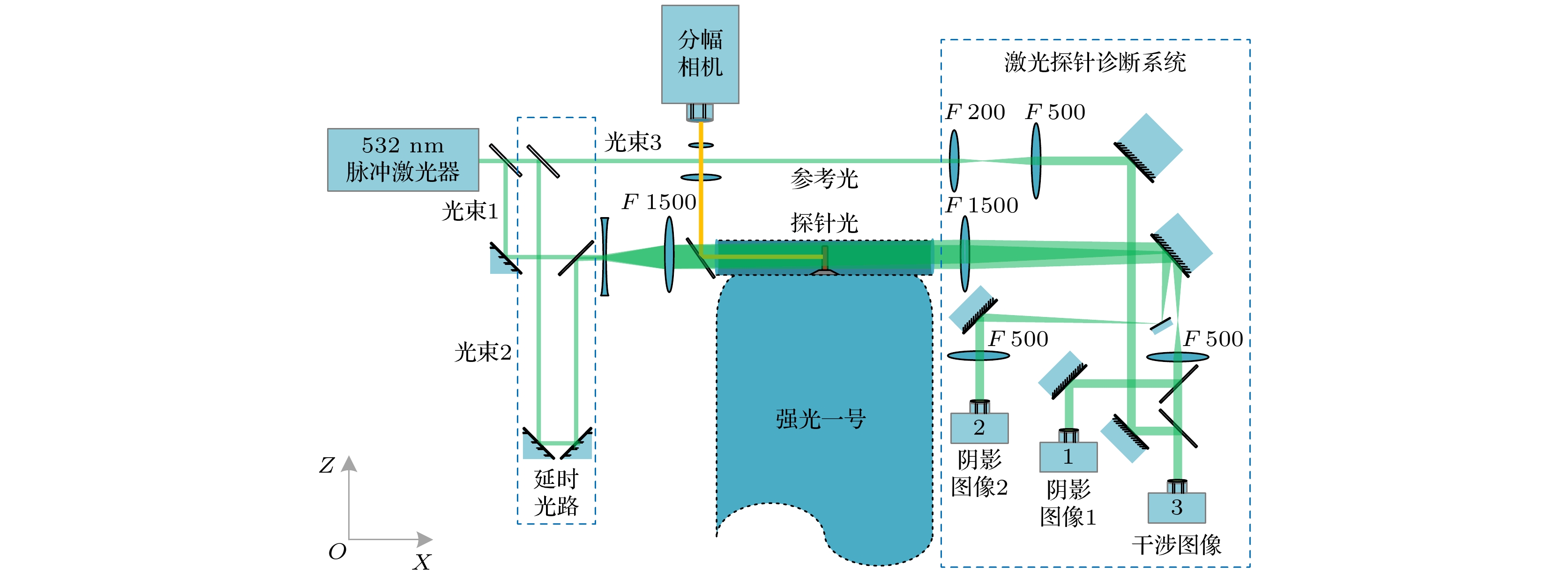 图 1 实验系统诊断布局
Figure1. Diagnostic system on “Qiangguang-1” facility.
 图 2 负载结构说明 (a) 负载三维组装图; (b) 初始状态激光阴影成像; (c) 薄膜受力分析示意图
Figure2. Structure of experimental load assembly: (a) Three-dimensional graph of the load; (b) laser shadow graph of the load in the initial stage; (c) force analysis of the foils in the planar geometry.
通过光刻结合化学腐蚀的过程在铝金属薄膜单侧表面上制备了周期为2 mm的一维凹槽型微结构, 其槽间距与槽宽相等, 刻蚀槽深~10 μm为总厚度的30%. 以符号p表示刻蚀周期, d表示刻蚀槽深, M表示样品材料类型. 刻蚀样品在显微镜下的观测形貌如图3所示. 表1汇总了实验所使用的具体薄膜参数. 实验过程中薄膜刻蚀面置于图2(b)所示的外侧界面端.
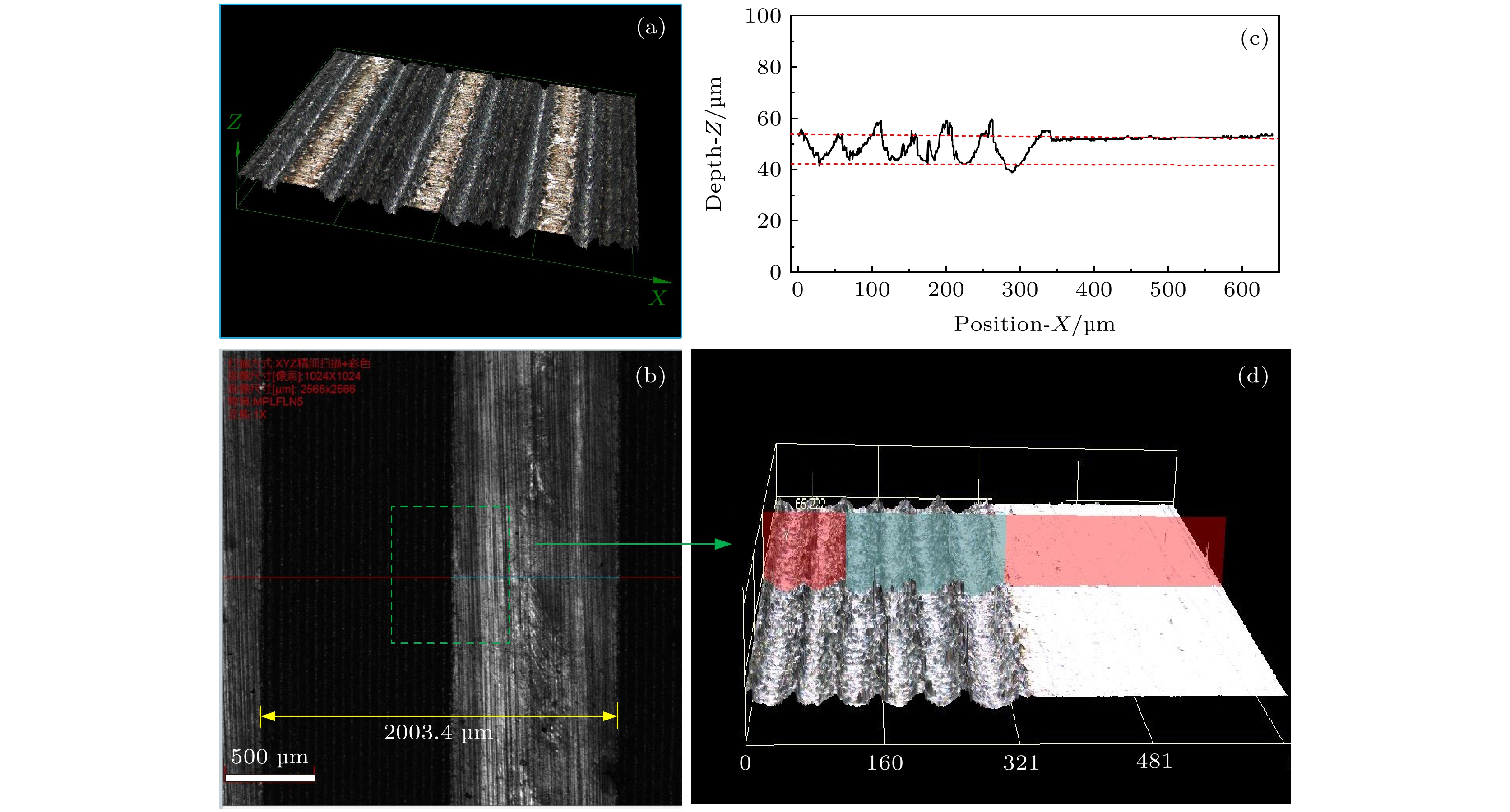 图 3 铝膜表面凹槽型周期刻蚀结构共聚焦显微镜扫描图 (a) 刻蚀结构三维形貌图; (b) 二维平面扫描图, 其单个刻蚀周期长度测量值为2003.4 μm; (c) 方框区域深度扫描曲线, 红线间距为10.2 μm; (d) 方框对应区域放大形貌
Figure3. Scanning graph of the periodical groove structure exploited on Al foil surface which was measured by confocal imaging microscope: (a) Three-dimensional scanning image; (b) surface scanning image which shows that the measured period of structure is 2003.4 μm; (c) the depth curve in which the etched depth between the red lines is 10.2 μm; (d) the enlarged image corresponding to the region of green box in (b).
| 材料M | 厚度 h/μm | 刻蚀槽深d/μm | 刻蚀周期p/mm | 宽度w/mm | 长度l/mm | 中心距r/mm |
| 铝(刻蚀) | 30 | 10 | 2 | 1 | 2 | 10 |
| 铝(镀膜) | 20 + 10 (PI) | # | # | 1 | 2 | 10 |
| 铝(标准) | 20 | # | # | 1 | 2 | 10 |
| 注: PI表示聚酰亚胺有机膜, #表示无刻蚀结构. | ||||||
表1金属薄膜参数
Table1.Parameters of the foils used in the exploding experiments.
3.1.实验图像分析
实验监测流过负载电流波形见图4. 以曲线峰值10%和90%点间连线与时间基轴的交点定义为时间零点, 对所有波形数据进行同步较零, 标注爆炸时刻以校正零时刻为基准, 以符号t表示. 图中实线(No. 19063—No. 19101)为各发次下装置罗氏线圈测得的负载总电流波形, 虚线为利用放置在薄膜外侧附近的B-dot探针诊断并经归一化处理后所得数据(No. 19273-B2)及同发次下的罗氏线圈对比数据(No. 19273-B1). 从波形上看标准薄膜(No. 19101)与刻蚀薄膜(No. 19063—No. 19074)的负载电流没有发生明显歧化, 两者在0—150 ns的时域内保持了良好的一致性, 刻蚀结构未影响总电流的馈入. B-dot测量信号的积分波形与罗氏线圈测得的电流波形则在0—110 ns的范围内基本一致, 说明电流上升的主要阶段薄膜局部磁场信息变化同步于总电流变化. 电流峰值过后的下降阶段两波形逐渐偏离, 原因主要在于烧蚀等离子体的外爆运动溅射在B-dot探头, 同时薄膜膨胀导致的内外侧界面分离使得整体磁场复杂化. 由单发次实验B-dot失效时间所推断出等离子体外爆的平均膨胀速度为

 图 4 不同实验发次下总电流波形汇总图
Figure4. Current trace for normal and etched cases.
图5为不同类型薄膜在相近爆炸时刻下的激光阴影图, 图6为提取对应边界结构的波谱分析. 实验结果显示刻蚀薄膜界面等离子形态的宏观特征得到了明显调制, 而普通薄膜与涂层薄膜并无此效果. 标准铝膜外爆实验中(图5(a))边界不稳定性结构以本征模式占主导. 在电热不稳定性等因素提供的种源[23]下, 铝膜的内外界面在发展初期均形成波长~0.5 mm的准周期结构. 但由于环境的非对称性, 内外侧不稳定结构发展逐渐差异化, 体现为外侧以大幅值短波结构主导, 内侧特征则为小幅值长波结构(图6(a)). 内侧强磁压导致界面运动减速而引发磁瑞利泰勒不稳定性是该侧长波特征显著增强的原因. 有机涂层薄膜实验中(图5(c))在外层边界处可以看到形成了宽晕带, 其中夹杂细长的等离子体细丝结构而金属核区相对平整. 有机膜在早期的融蚀过程起到了填充效应, 阻碍了镀膜界面处烧蚀等离子体的流动和质量的再分布过程, 从而在一定程度上抑制了界面的不稳定性发展, 起到了致稳性作用[11], 但其不稳定结构的基本形态特征并未改变. 图5(b)与图5(d)为相应时刻下的刻蚀薄膜实验结果, 观察发现其不稳定性结构发生显著改变. 受到刻蚀结构的趋同调制, 实验中铝膜外侧界面等离子形态呈现出与刻蚀样貌同周期的近似形态. 图6(b)显示在刻蚀薄膜的波谱观测到3个特征峰, 外侧分别为0.48, 0.92, 1.77 mm (t = 114 ns), 其中主峰最强为1.77 mm与刻蚀波长2 mm对应, 其误差主要来源于提供快速傅里叶变换的数据长度. 说明刻蚀结构决定了等离子体发展结构的主要形态. 次峰为0.95 mm对应主刻蚀周期一半, 出现特有的“半波结构”调制现象. 通过比对初始图像发现, 该衍生现象来源刻蚀沟槽几何突变位置处产生的等离子体喷流. 由于刻蚀沟槽的间距与谷宽相同, 因此形成的喷流结构等距, 其周期恰对应刻蚀周期的一半. 说明调制形成的特异位能够产生特殊等离子体结构. 最小特征峰对应0.48 mm的波长, 是铝材料的特征波长结构, 在刻蚀调制下该结构依然存在, 但相对幅度较小其特征性弱化. 说明大尺寸刻蚀结构能够一定程度抑制本征短波结构. 为进一步突出结构特征, 图7给出了波谱去噪后利用逆快速傅里叶变换重构得到的边界结构图, 以2 mm为主周期的块状结构, 在其两侧形成凸起峰, 构成1 mm的周期成分, 两者共同构成叠加形态.
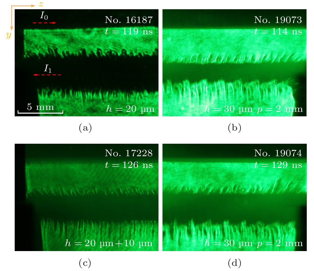 图 5 不同调制铝膜实验过程激光阴影图对比 (a) 标准铝膜119 ns时刻图(No. 16187); (b) 2 mm刻蚀周期结构铝膜114 ns时刻图(No. 19073); (c) 镀膜铝膜126 ns时刻图(No. 17228); (d) 2 mm刻蚀周期铝膜129 ns时刻图(No. 19074)
Figure5. Laser shadow graphy images for different Al foils in experiments: (a) Normal Al foil at 119 ns of No. 16187; (b) Al foil with 2 mm etched periodical structure at 114 ns of No. 19073; (c) coated Al foil at 126 ns of No. 17228; (d) Al foil with 2 mm etched periodical structure at 129 ns of No. 19074.
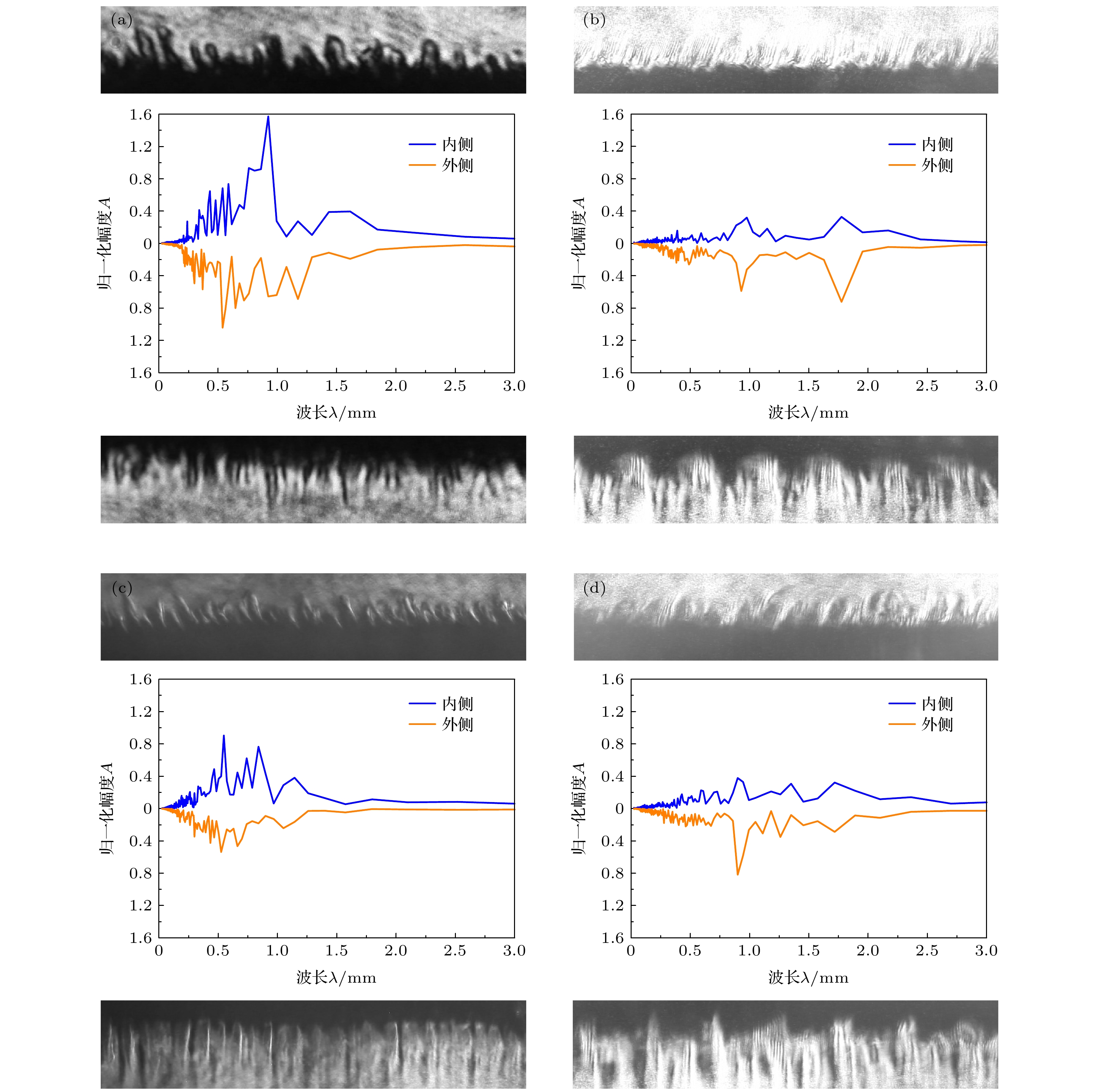 图 6 边界不稳定结构波谱分析 (a) 标准铝膜, No. 16187; (b) 2 mm刻蚀周期结构铝膜, No. 19073; (c) 镀膜铝膜, No. 17228; (d) 2 mm刻蚀周期结构铝膜, No. 19074
Figure6. Wavelength spectra analysis of the instability structure in experiments: (a) No. 16187 for normal case; (b) No. 19073 for 2 mm periodical structure sample; (c) No. 17228 for coated sample; (d) No. 19074 for 2 mm periodical structure sample.
 图 7 滤波后的逆快速傅里叶变换重构图
Figure7. Reconstructure image of the result by inverse fast Fourier transform.
与外侧相似, 内侧波谱在0.39, 0.97, 1.77 mm处出现峰值, 内侧的波峰强度较小同时不稳定结构的幅值也更小. 这与普通薄膜的内外侧特征形成强烈反差. 利用互相关函数计算得到的内外边界关联系数为0.4017 (图5(b)), 普通薄膜 (图5(a))的这一数值仅为0.0717, 说明即使刻蚀结构仅存于外侧, 内侧依然会受到较强的调制作用, 并且刻蚀调制能够进一步增强内外界面的馈通性与耦合性.
为进一步验证刻蚀结构的调制作用. 图8为1 mm刻蚀结构平面薄膜的实验结果. 其中内外界面均在0.47和0.92 mm (t = 90 ns)处出现特征峰. 刻蚀结构达到了趋同效果. 而由于半波效应, 在0.5 mm处的原特征波峰得到了明显增强. 可见刻蚀调制既可以抑制不稳定性结构的本征波长, 亦可以反向增强该结构特征, 调制效果存在多用性.
 图 8 1 mm刻蚀周期铝膜实验结果(No. 19067) (a) 90 ns时刻激光阴影图; (b)边界不稳定结构波谱分析
Figure8. Experiment results of the Al foil with 1 mm etched periodical structure (No. 19067): (a) The laser shadow graphy image at 90 ns; (b) the wavelength spectra analysis.
图9进一步给出表面周期刻蚀薄膜的爆炸过程随时间发展的激光阴影图像序列. 图9 中114 ns时刻图像中清晰显示出调制结构的形成, 129 ns时刻显示凸起的块状结构此后逐渐展宽, 烧蚀等离子体加速膨胀, 138 ns时刻下凸起结构等离子体逐渐融合, 158 ns时刻特征形态崩塌, 块状调制结构基本消失, 融合成为整体. 受外侧调制作用影响, 内界面MRT不稳定性特征明显减弱, 其波谱特征趋于外侧且不稳定结构幅值始终维持在较低水平, 刻蚀调制实现了对内界面的致稳作用.
 图 9 2 mm刻蚀周期铝膜激光阴影图序列 (a) 实验发次与对应时刻, No. 19073-114 ns, No. 19074-129 ns, No. 19072-138 ns, No. 19060-158 ns; (b) 114 ns时刻下局部结构放大伪色图; (c) 129 ns时刻下局部结构放大伪色图; (b), (c)中右侧标尺代表颜色域与灰度值的对应关系
Figure9. Laser shadow graphy image sequence for the Al foils with 2 mm periodical structure: (a) Corresponding shot numbers are No. 19073-114 ns, No. 19074-129 ns, No. 19072-138 ns, No. 19060-158 ns; (b) enlarged image of the box at 114 ns; (c) enlarged image of the box at 129 ns. Flase color has been added in (b) and (c) where the corresponding relationship between color and gray-scale value is shown in the label on the right.
图10为初始结构与实验过程中界面结构对照图. 铝膜在爆炸发展过程中界面处膨胀更快的凸起结构对应爆炸前的刻蚀凹槽处, 实验等离子体结构发展与初始结构反相. 这说明刻蚀沟槽处的金属层等离子体化发展的更早更迅速. 图11的可见光图像同样清晰地捕捉到这一特征, 在37 ns时刻下刻蚀结构对边界自辐射强度就已经产生了明显的调制作用, 形成独有的周期排布点亮现象, 至97 ns时刻发展成亮包状周期排布结构. 在圆柱形刻蚀丝阵的实验中, 研究者发现在单丝刻蚀形成的窄径处, 生成的等离子体冕层也更小, 从而与窄径处携带电流密度更大, 丝核烧蚀速度更快, 冕区等离子体层膨胀区域更广的预期相违背[1]. 而本文刻蚀薄膜实验观测到的反转结构则验证了这一预期. 另一方面在刻蚀丝阵实验中发现, 丝径跃变位置在X射线针孔成像中出现更强的亮斑, 并最先发展成为磁泡状的内爆结构. 而在刻蚀薄膜实验中, 在刻蚀断层处同样观测到特殊的喷流结构. 对比说明刻蚀丝阵中的单丝过程与刻蚀平面薄膜的外爆过程在调制等离子体发展过程中存在一定的差异, 但在特殊刻蚀区域中两者存在相似特征.
 图 10 初始薄膜刻蚀结构与实验发展过程结构对照 (a) 初始薄膜实物放置图; (b)初始状态侧向激光阴影成像图; (c) 实验激光阴影成像图
Figure10. Initial structure of foil surface comparing with developing plasma structure in experiments: (a) The photograph of actual etched foil; (b) the side-on laser shadow graphy image of Al foil before experiment; (c) corresponding shadow graphy image in experiment.
 图 11 刻蚀薄膜电爆炸过程早期可见光分幅图像, 其中实验发次No. 19274, 对应拍摄幅次与时刻依次为C1-37 ns, C2-57 ns, C3-77 ns, C4-97 ns
Figure11. Multiframe optical self-emission images of exploding etched Al foils for No. 19274. The frame number and shoot time are C1-37 ns, C2-57 ns, C3-77 ns, C4-97 ns respectively.
2
3.2.调制作用的电热理论分析
周期性刻蚀结构对电流密度的调制所引起的电热不稳定性分布特征的变化, 是调制效果产生的重要原因. Oreshkin[24]在对单丝分析的模型中认为电流密度j沿z向一致, 由电热不稳定性理论推导出色散公式. 在此基础上采用电流密度j沿z轴呈周期性分布的假设开展磁流体理论分析.由连续性方程, 动力学方程和热学方程得


 图 12 周期性刻蚀结构与对应位置增长率示意图
Figure12. Periodical structure and the growth rate of the corresponding position.


从物理上理解表面调制作用源于周期结构对表面电流的调制而造成局部电热性质差异. 对于实验中薄膜的电爆炸过程, 定性认为电流主要在薄膜内外边界层的趋肤深度内分布形成双电流层结构. 普通薄膜条件下电流密度在层内沿流向均匀分布, 电热不稳定性无差异化发展. 当界面引入人工刻蚀结构时, 未刻蚀凸起部位将形成势垒, 导致流经初始结构凸起部位金属层的电流路径阻性变强, 限制了电流的流入, 致使电流密度降低, 电热效应减弱, 因此凸起处等离子体化过程变缓, 原沟槽处金属率先等离子体化膨胀喷出. 另一方面由于凸起部位处等离子体化放缓, 因此在早期起到了类似有机膜镀层, 抑制界面不稳定性发展的效果. 这使得凸起部位下方的热化金属层被压实, 难以向外膨胀喷出. 受阻过程使得压力向两侧转移, 在凸起处与沟槽处过渡的台阶部位得以释放, 因此在该位点形成了细长的等离子体喷流, 导致半波结构的产生.
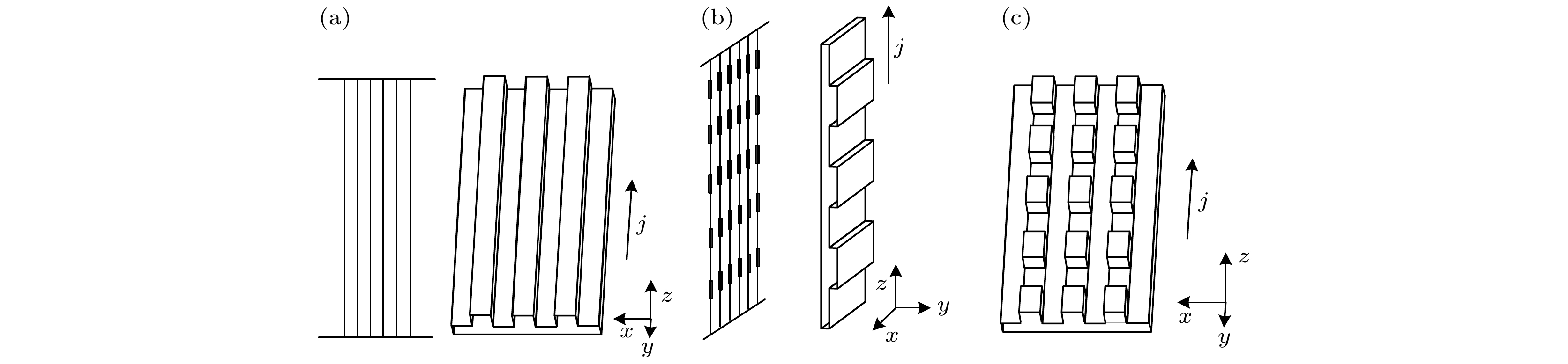 图 13 不同调制构型实验对比 (a)薄膜刻蚀取向沿z轴; (b)刻蚀平面丝阵与刻蚀平面薄膜对比; (c)二维刻蚀结构平面薄膜
Figure13. Different etched structure designed in future: (a) Etched along z axial; (b)planar array using etched wires; (c) two-dimensional etched structure on foil surface.
