Fund Project:Project supported by the National Natural Science Foundation of China (Grant No. 11674168)
Received Date:30 August 2020
Accepted Date:28 October 2020
Available Online:21 February 2021
Published Online:05 March 2021
Abstract:In this paper, we theoretically study the condition for the strong coupling between magnetic resonance mode of the two-dimensional periodically arranged gold split-ring resonators and the diffraction mode of the periodic array and its influence on the second harmonic generation efficiency. By controlling the size of the period of the array structure in the x-axis and y-axis, the diffraction mode is excited near the magnetic resonance provided by the gold split-ring resonator, solely in one of the directions. In both cases, the diffraction mode and the magnetic resonance coincide in the linear resonance spectrum, but by analyzing the electric field distribution at the position of the diffraction mode, it can be found that when ${a_x}$ is much larger than ${a_y}$, the electric field direction of the diffraction mode is perpendicular to the polarization direction of the incident light, and no strong coupling occurs. Therefore, the dilution effect is dominant, and the second harmonic intensity gradually decreases with the increase of the period. When ${a_y}$ is much larger than${a_x}$, the electric field direction of the diffraction mode is the same as the polarization direction of the incident light. At this time, the diffraction mode and the magnetic resonance mode are strongly coupled. As the period increases, the second harmonic intensity first increases and then decreases. The increase is due to the dominant mode coupling and the decrease is due to the dominant dilution effect. When the number density of split-ring resonators is reduced to about 1/4 of the original one, the second harmonic intensity can be increased by more than twice. From this, we find that the strong coupling between diffraction mode and magnetic resonance can occur when the electric field direction of the diffraction mode is consistent with the polarization direction of incident light, thus generating the surface lattice resonance to achieve near-field enhancement. In short, the rectangular periodic structure is used to distinguish the field enhancement effects in different directions, and the second harmonic enhancement can still be achieved when the number density of split-ring resonators is reduced, which relaxes the requirements for processing technology. This research provides a new possible way to improve the second harmonic generation efficiency based on metal metasurfaces. Keywords:strong coupling/ gold split-ring resonators/ diffraction mode/ second harmonic
全文HTML
--> --> --> 1.引 言局域表面等离激元(localized surface plasmons, LSPs)是指单个金属微纳结构表面的自由电子在特定频率电磁波照射下发生的非传导集体振荡[1,2]. 由于其拥有将电磁能量局域在亚波长尺度的特性, 从而能极大增强光与物质的相互作用, 故基于超表面的LSPs共振在生物传感器[3-9]、表面增强拉曼散射[10-15]、非线性增强[16-22]等领域已有广泛的应用. 然而, 金属纳米颗粒的LSPs寿命短、衰减快, 使得LSPs的共振谱线线宽较宽, 这在一定程度上限制了对光场的局域能力. 此外, 单个金属微纳结构的LSPs共振和周期金属微纳阵列的衍射模式之间可以通过模式耦合从而产生表面晶格共振(surface lattice resonances, SLRs). 与LSPs共振相比, SLRs的线宽更窄, 即具有更高的Q因子, 因此, 金属微纳结构周围的场强有更明显的增强, 基于金属阵列结构的超表面会产生强光学性质, 这种增强效应在传感技术[23]、激光技术[24]及光与物质相互作用的强耦合实验[25,26]、固态照明[27]等领域被广泛研究. 近期, SLRs被用于研究基于超表面周期阵列结构的二次谐波产生 (second harmonic generation, SHG) 增强[28], 其原理是通过增大周期结构的尺寸, 在金属V型单元结构共振附近引入衍射模式, 通过模式耦合产生表面晶格共振, 使共振线宽变窄实现场增强, 所以, 在单元结构密度减少一半的情况下, SHG可以得到5倍的增强. 另外, 我们发现, 之前关于表面晶格共振增强非线性的研究大多是基于正方周期阵列, 通过改变入射角或周期尺寸来研究表面晶格共振的产生及影响, 但正方阵列使x, y方向的模式发生简并, 无法区分不同方向共振模式对应的场增强效果, 以及是否对非线性增强产生有效的影响. 在本文中, 计算的单元结构是开口环谐振器, 这是因为产生二次谐波的条件是结构中心对称性破缺, 而且在之前的研究中, 通过比较多种不同类型的单元结构[29], 发现利用开口环谐振器计算的二次谐波产生效率最好. 我们分别改变了x, y两个方向的周期大小, 基于长方周期结构研究不同方向周期的变化产生的衍射模式与金开口环谐振器在电磁波激发下产生的LSPs共振的强耦合过程, 以及二次谐波强度在改变不同方向周期尺寸下的变化规律, 在此基础上, 结合电场分布情况进一步分析表面晶格共振的产生机制. 2.模型与方法图1给出了处于均匀介质环境中的金开口环谐振器(split-ring resonators, SRRs)阵列的结构示意图及开口环谐振器的单元结构图. 如图所示, ${a_x}, {a_y}$分别表示SRRs阵列在x和y方向上的周期大小, 阵列所处环境的折射率为1.459, l是开口环谐振器的边长, w是两底部间距, d代表两臂间距, h表示单元结构的厚度, 关于线性透射谱和二次谐波强度的计算是基于有限元仿真软件COMSOL Multiphysics, SRRs的材料设定为金, 介电常数采用Drude模型, 即${\varepsilon _{{\rm{Au}}}}\left( \omega \right) = 1 - \left[ {{{\omega _{\rm{p}}^2} / {\left( {{\omega ^2} + {\rm{i}}\omega \gamma } \right)}}} \right]$, $\omega $是入射电磁波的角频率, ${\omega _{\rm{p}}}$和$\gamma $分别代表金的等离子体频率和衰减速率, ${\omega _{\rm{p}}} = 1.37 \times {10^{16}}$ Hz, $\gamma = 1.22 \times {10^{14}}$ Hz, 入射光设为平面波形式, 电场沿x方向偏振, 并沿–z方向垂直入射于SRRs阵列. 为防止杂散光对仿真计算结果产生影响, 故将模拟区域的上下底面设置为完美匹配层和散射边界条件, 并考虑到结构为周期阵列, 侧面采用周期性边界条件. 透射谱是通过计算不同入射电磁波透过周期阵列结构的能量与入射光波能量的比值得到的, 由于金属表面等离子体的趋肤深度是有限的, 大约为0.1 nm, 所以依据金属非线性表面极化强度可以计算出金属有效非线性表面电流密度关系式, 具体计算方法可以参考文献[29], 通过设置金开口环谐振器表面电流密度的3个分量, 可以计算出二次谐波强度的变化. 图 1 (a) 处于均匀介质中的金开口环谐振器阵列结构示意图, x, y方向的周期分别为${a_x}$, ${a_y}$, 入射光垂直照射于阵列结构, 电场方向沿x轴; (b) SRRs单元结构图, 其中$l = 200\;{\rm{nm}}$, $w = 80\;{\rm{nm}}$, $d = 100\;{\rm{nm}}$, $h = 30\;{\rm{nm}}$ Figure1. (a) Schematic of SRRs array, the period of the x axis and y axis is ${a_x}$ and ${a_y}$, respectively, the incident light is perpendicular to the structure, and the electric field is along the x axis; (b) the unit cell of SRRs, where $l = 200\;{\rm{nm}}$, $w = 80\;{\rm{nm}}$, $d = 100\;{\rm{nm}}$, $h = 30\;{\rm{nm}}$.
3.结果与讨论首先, 我们计算了两种周期阵列结构的透射谱, 如图2所示, 这两个周期结构的${a_y} = 400\;{\rm{nm}}$, ${a_x}$分别等于400 nm和1200 nm, 从图中可以发现, 两个透射谱都有一个宽带透射谷(Dip1), 该位置是开口环谐振器的磁共振模式, 位置几乎不随周期的改变而改变, 图1中插图表示Dip1位置x-y截面的磁场分布图和电流分布情况, 红色箭头代表电流, 从插图中的环形电流分布图也可以看出, 该位置是SRRs被激发的磁共振模式. 但在${a_x} = 1200 \;{\rm{nm}}$的透射谱中还存在一个窄带透射谷(Dip2), 该位置是由周期结构引入的衍射模式, 之后我们会对Dip1和Dip2的位置随周期的变化规律进行详细地分析. 图 2${a_y} = 400\;{\rm{nm}}$固定不变, ${a_x} = 1200\;{\rm{nm}}$ (黑线)和${a_x} = 400\;{\rm{nm}}$ (红线)两种不同周期阵列结构的透射谱, 插图表示宽带透射谷(Dip1)位置x-y截面的磁场电流分布图 Figure2. The transmission spectrum of two different periods along the x axis, ${a_x} = 1200\;{\rm{nm}}$ (black line) and ${a_x} = 400 \;{\rm{nm}}$ (red line). The insert shows the distribution of magnetic field and current in x-y section at the position of Dip1.
为探索衍射模式和磁共振模式发生强耦合所需要满足的条件, 我们分别研究了只改变x方向周期${a_x}$和只改变y方向周期${a_y}$两种情况下的耦合过程. 如图3所示, 图3(a) 和图3(b) 表示保持${a_y} = 400\;{\rm{nm}}$固定不变, 只改变${a_x}$时的透射谱和两透射谷位置随周期的变化规律. 图3(c) 和图3(d) 分别与图3(a) 和图3(b) 相对应, 区别在于${a_x} = 400\;{\rm{nm}}$固定不变, 而${a_y}$从1200 nm变化到1500 nm, 图3(a),(c)展示了金开口环谐振器阵列结构的透射谱, 可以观察到每一个透射谱都有两个透射谷:一个是窄带, 一个是宽带. 图3(b) 和图3(d)中空心圆圈代表了这两个透射谷位置随周期的变化规律; 黑色实线代表单个金开口环谐振器的磁共振, 磁共振的位置由金属材料特性和开口环谐振器的几何参数决定, 但不受阵列周期的影响; 蓝色实线代表介质环境中衍射模式随周期移动的曲线图; 两条红色曲线代表拟合的混合模式态—高能态和低能态, 该混合模式态由金属开口环谐振器激发的LSPs共振和周期结构Wood异常引入的衍射模式耦合形成, 二者能量可以通过耦合共振模型来计算[30]: 图 3${a_y} = 400\;{\rm{nm}}$, ${a_x} = 1200$—1550 nm (间隔50 nm) 时的 (a) 线性透射谱及(b) 透射谱中两透射谷随周期的变化; ${a_x} = 400\;{\rm{nm}}$, ${a_y} = 1200$—1500 nm (间隔50 nm)时的 (c) 线性透射谱及(d) 透射谱中两透射谷随周期的变化 Figure3. (a) Linear transmission spectrum and (b) the positions of two dips in transmission spectrum change with the period along the x axis, ${a_y} = 400\;{\rm{nm}}$, ${a_x} = 1200\!-\!1550 $ nm (interval 50 nm); (c) linear transmission spectrum and (d) the positions of two dips in transmission spectrum change with the period along the y axis, ${a_x} = 400\;{\rm{nm}}$, ${a_y} = 1200\!-\! 1500$ nm (50 nm interval).


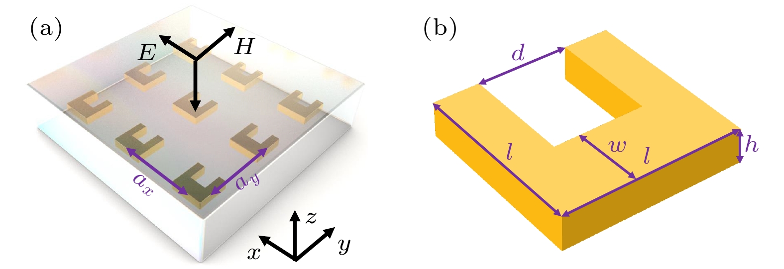 图 1 (a) 处于均匀介质中的金开口环谐振器阵列结构示意图, x, y方向的周期分别为


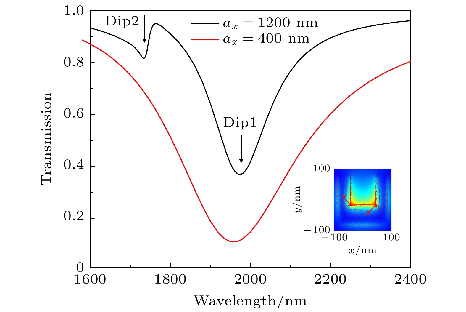 图 2
图 2 


 图 3
图 3 


 图 4 (a)


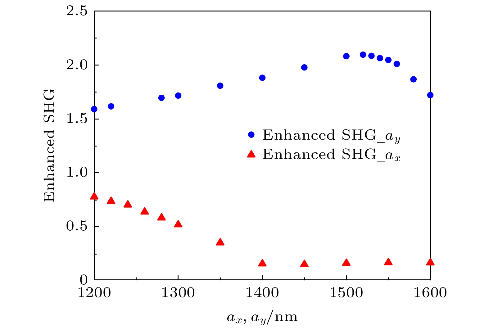 图 5 固定


