1.School of Information Science and Engineering, Yunnan University, Kunming 650091. China 2.School of Science, Yunnan Agricultural University, Kunming 650201, China
Fund Project:Project supported by the National Natural Science Foundation of China (Grant Nos. 61461052, 11564044, 61863035) and the Science Research Foundation of the Education Department of Yunnan Province, China (Grant Nos. 2019J0172, 2020J0005)
Received Date:14 August 2020
Accepted Date:07 September 2020
Available Online:03 February 2021
Published Online:20 February 2021
Abstract: In this paper, we propose three plasmon-induced transparency(PIT) hybrid models based on the coupling of black phosphorus (BP) nanorods. By using the bright-bright mode coupling between BP nanorods with different lengths, and according to the weak hybrid effect after the detuning of each bright mode unit, we can trigger the single-band, dual-band and triple-band PIT effects. Secondly, by changing the relaxation rate of BP, the resonant frequency can be adjusted in each PIT model. When the relaxation rate of BP changes from small to large, the resonance frequencies of the transparent windows in those three PIT models all increase and the blue shifts occur. In a single-band PIT model, when the relaxation rate of BP changes from $0.8 \times {10^{ - 14}}$ to $1.4 \times {10^{ - 14}}\;{{\rm{cm}}^{ - 2}}$, the resonant frequency of transparent window increases 7.5628 THz. In a dual-band PIT model, under the same change of relaxation rate, the resonant frequencies of the two transparent windows increase 6.8593 and 9.1457 THz, at the same time, and the resonant frequencies of the three transparent windows in triple-band PIT model increase 6.8593, 8.7939 and 11.2563 THz respectively. In addition to the resonant frequency, the transmittance at the dip frequency in each model gradually decreases, and the depth of depression gradually increases. Finally, the sensing characteristics of the single-band PIT model are further studied. When the refractive index of the background changes from small to large, the dip frequency and the resonant frequency of the transparent window will be significantly red-shifted. The change of frequency is approximately linear with refractive index. The model has a sensitivity of 6110.6 (nm/RIU) and a figure of merit of 7.39 (1/RIU) which is better than the same type of sensor. This model provides a theoretical reference for designing the multiband filtering and ultrasensitive sensors. Keywords:plasmon-induced transparency/ black phosphorus/ finite difference time domain
图 2 BP原子结构和介电常数示意图 (a) BP错列原子结构示意图; (b) ${\varepsilon _{xx}}$实部随${n_{\rm{s}}}$的变化规律; (c) ${\varepsilon _{xx}}$虚部随${n_{\rm{s}}}$的变化规律; (d) ${\varepsilon _{yy}}$实部随${n_{\rm{s}}}$的变化规律; (e) ${\varepsilon _{yy}}$虚部随${n_{\rm{s}}}$的变化规律 Figure2. Schematic diagrams of BP atomic structure and dielectric constant: (a) The staggered atomic structure of BP; (b) variations of the real part of ${\varepsilon _{xx}}$ with different ${n_{\rm{s}}}$; (c) variations of the imaginary part of ${\varepsilon _{xx}}$ with different ${n_{\rm{s}}}$; (d) variations of the real part of ${\varepsilon _{yy}}$ with different ${n_{\rm{s}}}$; (e) variations of the imaginary part of ${\varepsilon _{yy}}$ with different ${n_{\rm{s}}}$.
图9给出了当BP弛豫速率${n_{\rm{s}}} \!=\! 1.0 \!\times\! {10^{14}}\;{\rm{c}}{{\rm{m}}^{ - 2}}$时, 双频段和三频段PIT模型的透射率曲线. 作为参考, 图9中同时给出了相同${n_{\rm{s}}}$条件下, 不同长度的BP纳米棒阵列的透射率曲线. 由图9(a)可以看出, 双频段PIT模型的透射谱曲线中出现了两个透明窗口peak I和peak II. 在图9(b)中, 三频段PIT模型的透射谱曲线中出现了三个透明窗口peak I, peak II和peak III. 同时, 在双频段和三频段模型中, 不同长度的BP纳米棒阵列都产生了典型的洛伦兹线型的谐振, 因此和单频段模型一致, 双频段和三频段PIT效应同样是基于不同长度的BP纳米棒之间的明-明模耦合产生的. 图 9 双频段和三频段PIT的透射谱曲线 (a) 双频段PIT的透射谱曲线; (b) 三频段PIT的透射谱曲线 Figure9. Transmission spectra of dual-band PIT and triple-band models: (a) Transmission spectra of dual-band PIT model; (b) transmission spectra of triple-band PIT model.
为了验证双频段和三频段PIT效应的可调性, 图10和图11给出了BP弛豫速率${n_{\rm{s}}}$改变时, 双频段和三频段模型透射谱曲线的变化情况. 在图10中, 当${n_{\rm{s}}} = 0.8 \times {10^{ - 14}}\;{\rm{c}}{{\rm{m}}^{ - 2}}$时, peak I和peak II的谐振频率最小, 分别等于21.1558和28.0151 THz. 当${n_{\rm{s}}}$从$0.8\! \times\! {10^{ \!-\! 14}}\;{\rm{c}}{{\rm{m}}^{ - 2}}$增大到$1.4 \!\times\! {10^{ - 14}}\;{\rm{c}}{{\rm{m}}^{ \!-\! 2}}$时, peak I和peak II的谐振频率逐渐增大, 发生蓝移; 当${n_{\rm{s}}} = 1.4 \times {10^{ - 14}}\;{\rm{c}}{{\rm{m}}^{ - 2}}$时, peak I和peak II的谐振频率最大, 分别等于28.0151和37.1608 THz. 此外, 随着${n_{\rm{s}}}$的不断增大, dip A, dip B和dip C的透射率也逐渐减小, 下凹深度也逐渐增大. 图 10${n_{\rm{s}}}$由$0.8 \times {10^{ - 14}}\;{\rm{c}}{{\rm{m}}^{ - 2}}$变化到$1.4 \times {10^{ - 14}}\;{\rm{c}}{{\rm{m}}^{ - 2}}$时双频段PIT模型透射谱变化规律 Figure10. Variation law of transmission spectrum of dual-band PIT model when the ${n_{\rm{s}}}$ is changed from $0.8 \times {10^{ - 14}}$ to $1.4 \times {10^{ - 14}}\;{\rm{c}}{{\rm{m}}^{ - 2}}$.
图 11${n_{\rm{s}}}$由$0.8 \times {10^{ - 14}}\;{\rm{c}}{{\rm{m}}^{ - 2}}$变化到$1.4 \times {10^{ - 14}}\;{\rm{c}}{{\rm{m}}^{ - 2}}$时三频段PIT模型透射谱变化规律 Figure11. Variation law of transmission spectrum of triple-band PIT model when the ${n_{\rm{s}}}$ is changed from $0.8 \times {10^{ - 14}}$ to $1.4 \times {10^{ - 14}}\;{\rm{c}}{{\rm{m}}^{ - 2}}$.
在图11中, 三频段模型透射谱曲线随BP弛豫速率${n_{\rm{s}}}$的变化情况与单频段和双频段模型类似, 当${n_{\rm{s}}}$从$0.8 \times {10^{ - 14}}\;{\rm{c}}{{\rm{m}}^{ - 2}}$增大到$1.4 \times {10^{ - 14}}\;{\rm{c}}{{\rm{m}}^{ - 2}}$时, peak I, peak II和peak III的谐振频率逐渐增大, 发生蓝移. peak I的谐振频率从20.9799 THz增大到27.8392 THz, peak II的谐振频率从28.1910 THz增大到36.9849 THz, peak III的谐振频率从35.9296 THz增大到47.1859 THz. 同时, 随着${n_{\rm{s}}}$的不断增大, dip A, dip B, dip C和dip D的透射率同样逐渐减小, 下凹深度同样逐渐增大. 为了进一步研究双频段和三频段PIT模型的形成原理, 图12和图13给出了双频段和三频段透射谱曲线中的各波谷频率和透明窗口谐振频率处的电场分布. 在图12中, 在dip A处, 由于其与BP纳米棒C的谐振频率近似, 所以电场强度主要集中在纳米棒C的边缘和末端, 呈典型的电偶极模式分布. 在dip B和dip C处, 电场强度主要集中在BP纳米棒B和A的附近, 也呈电偶极模式分布. 图 12 双频段PIT模型在 (a) dip A, (b) dip B, (c) dip C, (d) peak I和(e) peak II的电场分布 Figure12. Distribution of electric field of dual-band PIT model at (a) dip A, (b) dip B, (c) dip C, (d) peak I nd (e) peak II.
图 13 三频段PIT模型在 (a) dip A, (b) dip B, (c) dip C, (d) dip D, (e) peak I, (f) peak II和(g) peak III的电场分布 Figure13. Distributions of electric field of dual-band PIT model at (a) dip A, (b) dip B, (c) dip C, (d) dip D, (e) peak I, (f) peak II and (g) peak III.


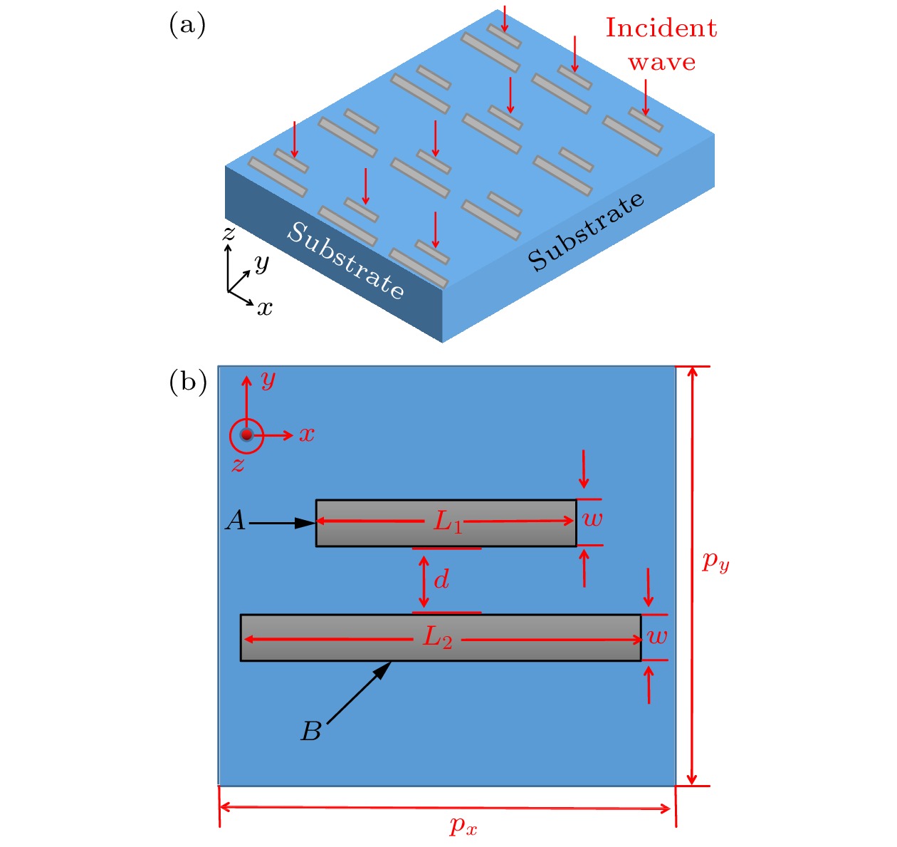 图 1 单频段PIT模型结构图 (a) 三维空间结构图; (b) 二维平面结构图
 图 2 BP原子结构和介电常数示意图 (a) BP错列原子结构示意图; (b)


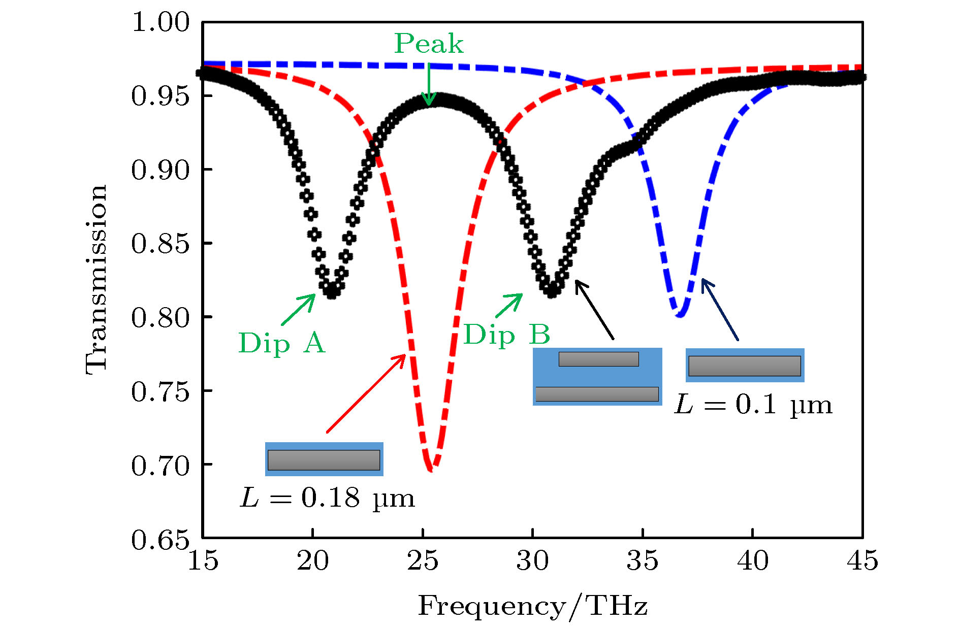 图 3 单BP纳米棒谐振器、单频段PIT模型的透射曲线透射曲线
 图 4 单频段PIT模型在dip A, dip B和peak的电场分布 (a) dip A; (b) dip B; (c) peak


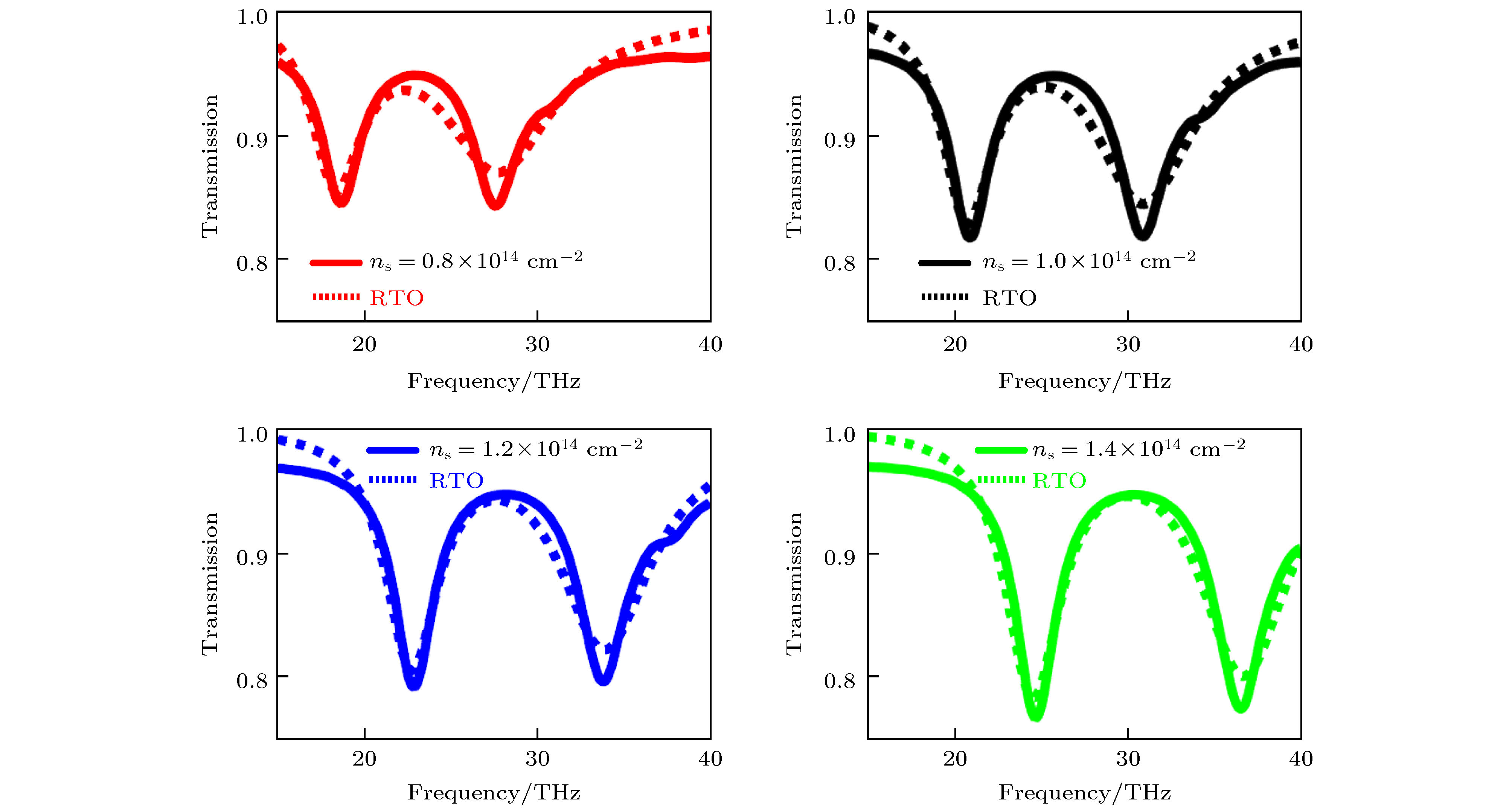 图 5
图 5 


 图 6 单频段PIT模型不同背景折射率下的透射窗对比
 图 7 单频段PIT模型中dip A, dip B和peak随背景折射率的变化规律


 图 8 双频段和三频段PIT模型二维结构图 (a) 双频段模型二维结构图; (b) 三频段模型二维结构图

 图 9 双频段和三频段PIT的透射谱曲线 (a) 双频段PIT的透射谱曲线; (b) 三频段PIT的透射谱曲线


 图 10
图 10 


 图 11
图 11 


 图 12 双频段PIT模型在 (a) dip A, (b) dip B, (c) dip C, (d) peak I和(e) peak II的电场分布
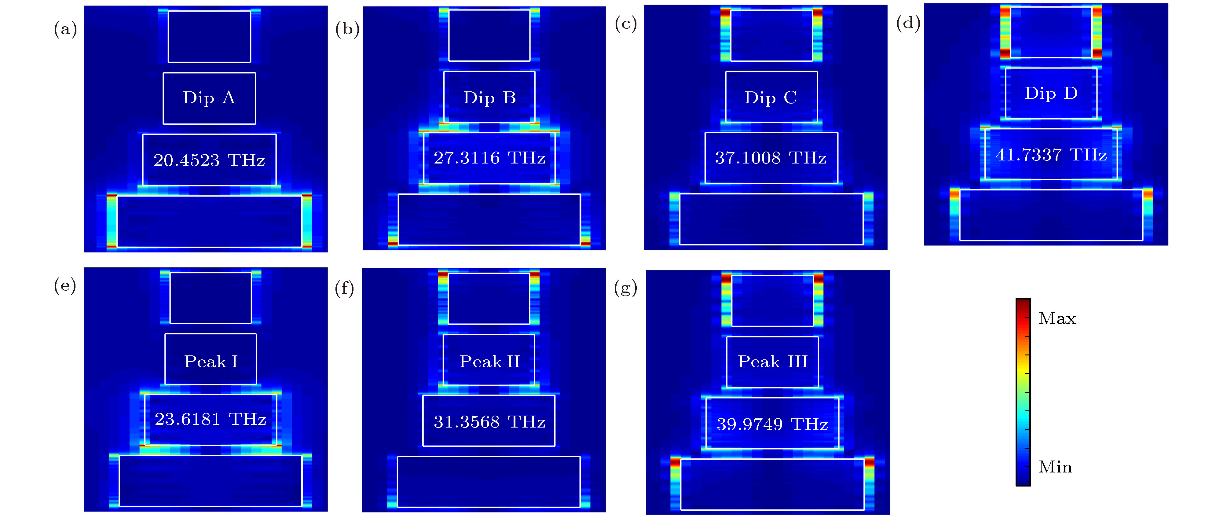 图 13 三频段PIT模型在 (a) dip A, (b) dip B, (c) dip C, (d) dip D, (e) peak I, (f) peak II和(g) peak III的电场分布

