全文HTML
--> --> -->目前, 场增强的主流方法主要有两种: 一是采用人工电磁材料(metamaterial)构造周期结构对辐射的电磁能量进行控制和集中, 从而令通过该结构的电磁辐射具有尖锐的方向图, 该方法主要应用于高方向性天线设计, 应用频率比较低, 难以直接应用于光学频段[2-9]; 另一种方法是采用具有高介电常数或高磁导率的材料来实现材料内部电磁场的汇聚与增强[10-17], 此方法对于材料内部辐射点源位置和材料截面积的变化极其敏感, 并严重依赖材料的相对介电常数εr或相对磁导率μr的数值, 即当εr (μr)越大时, 材料中心场的增强才越高, 但极限增强倍数为材料相对介电常数值(εr)的3/4次方[18]. 例如一个包含辐射点源的εr = 9的圆截面二维介质, 其圆截面中心场相比辐射源场增强了6倍, 所以材料电磁参数严重限制其场增强的效果, 显然无法满足激光点火等用途.
近年来的研究发现, 零折射率材料也具有良好的场汇聚与增强效应. 例如, 文献[19]提到近零磁导率(mu-near-zero, MNZ)材料环包围线电流的辐射场可以根据具体的几何结构得到增强或完全抑制. 但是MNZ材料难以实际制备, 且应用频率较低, 应用范围极其有限[19-23]. 从材料实现和更宽的应用频率角度出发, 近年来研究重点转移到利用近零介电(epsilon-near-zero, ENZ)材料媒质实现内部场增强效应上[24-30]. 上述工作对ENZ媒质实现场增强效应从理论上提供了许多启示, 但实用性方面指导仍显不足.
本文首先通过理论分析计算介质掺杂的ENZ媒质中电磁场的分布, 得出该结构中掺杂介质的中心场与ENZ媒质中场的比例关系, 并根据理论计算结果, 从实用性角度出发, 首次提出当该结构作为场强增强器件时所应满足的等效状态; 其次, 在结构满足该等效状态时, 从多方面对该结构的场强增强性能进行分析和全波数值仿真分析验证, 表明该结构能够非常显著地增强外部入射场强, 其场增强倍数完全满足激光点火等高场强应用需求, 并且在结构设计上具有很好的灵活性, 且适用于微波至光波波段的宽频谱范围; 最后, 作为实际应用探索, 设计了一款工作在270 nm紫外光波段的场增强装置. 本文工作为新型电磁(光学)点火器件的研制提供了新的思路.

 图 1 ENZ介质掺杂介质结构等效示意图(2D截面) (a) ENZ媒质掺杂介质结构截面图, 存在一个与截面垂直的磁流IM; (b) 具备相同截面大小的等效ENZ介质示意图, 在该截面相同的位置存在一个与图(a)相同的的磁流IM
Figure1. Schematics of magnetic ENZ medium filled with dielectric dopants: (a) A 2D magnetic ENZ medium with several macroscopic non-magnetic dielectric dopants and an alternating magnetic current IM embedded in the ENZ medium whose magnetic field H1 is polarized along y axis; (b) the equivalent homogeneous 2D ENZ medium with the same cross-sectional shape and near-zero permittivity, but a uniform equivalent relative permeability μeff
根据ENZ媒质的掺杂理论[31], 图1(a)结构可等效为一个具有相同横截面的均匀ENZ介质, 其等效相对磁导率为μeff, 如图1(b)所示. 考虑此时该等效ENZ媒质中同样位置上有一相同的磁流激励源IM, 则在图1(b)所示的结构中也将分别激励出磁场H2和电场E2. 上述等效假设能够保证图1(a)和图1(b)的结构具有相同的外辐射场, 同时各自边界上的切向电场也将相等. 而由于两个ENZ媒质中的磁场都是均匀的, 所以有H1 = H2.
令上述两个结构的边界曲线长度均为l, 对于图1(a)的结构有

(4)式说明掺杂介质内部的场是波动的, 且在中心点(r = 0)处达到最强, 即在该点体现出磁场汇聚现象, 这一点与文献[18]的结论一致. 另外, 从(1)式可得出一个重要结论, 即该结构对外辐射电场的切向分量沿着ENZ媒质边缘的环路积分应等于整个结构截面的总磁通量. 因此, 如果该结构无法对外形成有效辐射, 即ENZ媒质边缘的切向电场Et很小或为零, 则整个结构截面的总磁通量也将很小, 从应用角度来说, 就无法形成有效的内部磁场增强效应. 所以, 为形成明显的场增强效应, 首先应保证该结构处于有效的对外辐射状态, 这样才能保证结构截面内的磁场也很强. 根据上述分析, 从实际应用角度出发, 当掺杂介质的ENZ媒质结构处于等效电磁参数近零(epsilon-mu-near-zero, EMNZ)媒质时, 其磁场增强效应是最具有实际意义的. 当该结构为等效EMNZ媒质时, ENZ区域内的场与辐射源场(或外部辐射场)一致, 因此(4)式可有效地计算该结构中嵌入介质内部对辐射源(入射场)的场增强效果, 这一点对于电磁点火装置而言最具有应用价值.
2
3.1.ENZ媒质内掺杂单一介质
在无耗情况下, 作为分析实例, 设ENZ媒质的横截面积为2.5
通过(3)式计算可得到ENZ媒质在介质掺杂后其等效磁导率μeff随其半径变化的曲线(图2). 可见随掺杂介质半径变化, 整个结构的等效磁导率曲线呈现明显的周期性谐振. 在每个谐振峰附近, 都存在一个μeff接近零的点.
 图 2 ENZ媒质介质掺杂后其等效磁导率μeff随掺杂介质半径的变化
Figure2. Effective relative permeability (μeff) of the doped ENZ medium as a function of the doping rod radius.
考虑在ENZ媒质掺杂结构中的任意位置放置一个理想二维点源(磁流源, 产生y轴方向磁场), 在该结构等效为EMNZ媒质的前提下, 研究掺杂介质圆柱半径与该圆柱中心磁场增强倍数的关系. 根据图2可知, 随着掺杂介质圆柱半径的增加, 会出现一系列的谐振峰, 自然也会出现一系列的μeff为零的点. 根据(3)式计算出当rd/λ0 = 0.158, 0.363和0.572时, 该结构均可等效为EMNZ媒质(μeff ≈ 0), 由(4)式分别计算这三种情况下的掺杂介质内部磁场和ENZ中磁场(即激励源场)的比值ψd(r), 如图3(a)所示, 图3(a)中横坐标中的“0”点表示单个掺杂介质截面的圆心, 纵坐标定义为磁场强度增强系数F.
 图 3 掺杂介质具有不同半径时, 其内部中心磁场相对外辐射场的磁场增强倍数计算与仿真验证 (a) 掺杂介质内部中心磁场与其半径的关系曲线; (b) 理想点源的磁场仿真结果; (c), (d), (e) 掺杂介质半径分别为rd/λ0 = 0.158, rd/λ0 = 0.363和rd/λ0 = 0.572时掺杂介质ENZ媒质结构的磁场仿真结果
Figure3. Enhancement factors of internal magnetic field in the dopant compared with external radiation field with the different radius of dopant: (a) Enhancement factors of internal magnetic field in the dopant with different rd; (b) the simulation result of magnetic field of point source in free space; (c), (d), (e) simulation results of magnetic field in ENZ filled with dopant with different radius of dopant (rd/λ0 = 0.15659, 0.35958, 0.56427), respectively.
为了验证上述结果, 采用电磁场全波数值计算软件COMSOL对其进行仿真分析验证. 如果是自由空间中的一个理想点源, 激励磁场幅度为100 A/m, 其辐射磁场分布如图3(b)所示. 其次, 如果该点源置入截面积为2.5

2
3.2.ENZ媒质内含多个辐射源
在实际的激光点火应用中, 若需场强要求很高, 可采用多个点火激励源, 同时提供能量叠加到同一个点火区域, 此时采用掺杂介质的ENZ媒质结构也是十分适合的. 因为ENZ媒质内部磁场均匀, 相位相同, 当几个点源置于ENZ媒质中, 其辐射场强在ENZ媒质内具有相位相同, 并能在掺杂介质中心形成完美的干涉增强效果, 使辐射能量可以完美叠加于掺杂介质的截面中心. 据此, 本节对包含多个相同辐射源的介质掺杂ENZ结构的磁场增强效应进行分析. 仍采用图3(c)的结构参数, 但在ENZ媒质中任意位置设置了两个相同的激励点源.作为比较, 图4(a)(即图3(c))显示ENZ内为单点源时, 嵌入介质柱截面中心点的磁场幅值为7300 A/m, 场增强系数为73; 若再增加一个相同的辐射点源, 该结构介质柱截面中心点的磁场幅值增加到14000 A/m, 如图4(b)所示; 而改变两个辐射点源的嵌入位置, 结果与图4(b)相同, 如图4(c)所示; 同样保持ENZ横截面积不变, 将截面形状变为正方形, 仍得到相同的磁场分布, 如图4(d)所示. 因此, 介质掺杂ENZ媒质结构在多个源激励下, 具有良好的场强叠加增强能力, 且与源的位置及ENZ媒质截面形状无关, 这为大功率、大场强的点火装置的设计和实现提供良好的思路和途径.
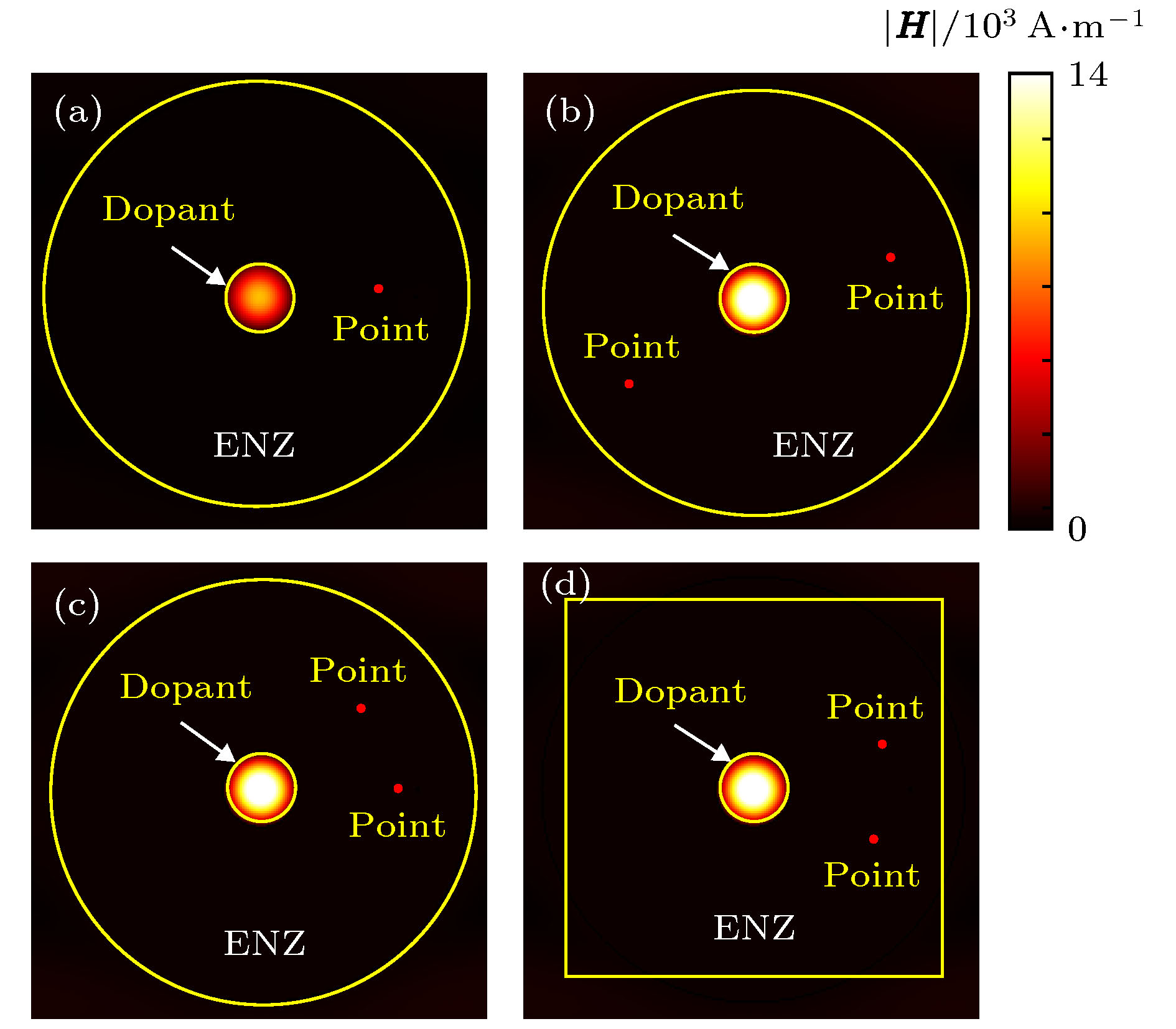 图 4 掺杂介质的ENZ媒质结构分别包含单个点源和两个点源时的磁场对比仿真 (a) 掺杂介质的ENZ媒质结构包含单个点源的磁场仿真结果(εr1 = 6, rd/λ0 = 0.158); (b) 在图4(a)结构中再增加一个点源的磁场仿真结果; (c) 调整4(b)结构两个点源位置的磁场仿真结果; (d) 改变图4(c) ENZ媒质截面形状后的磁场仿真结果(点源位置任意调整, ENZ截面积不变)
Figure4. Simulation results of magnetic field in ENZ medium filled with the dopant containing different point sources, respectively: (a) One point source embedded in the ENZ medium (εr1 = 6, rd/λ0 = 0.158); (b) two point sources embedded in the ENZ medium; (c) two point sources located somewhere in ENZ medium; (d) two point sources embedded in an ENZ square (with the same cross section).
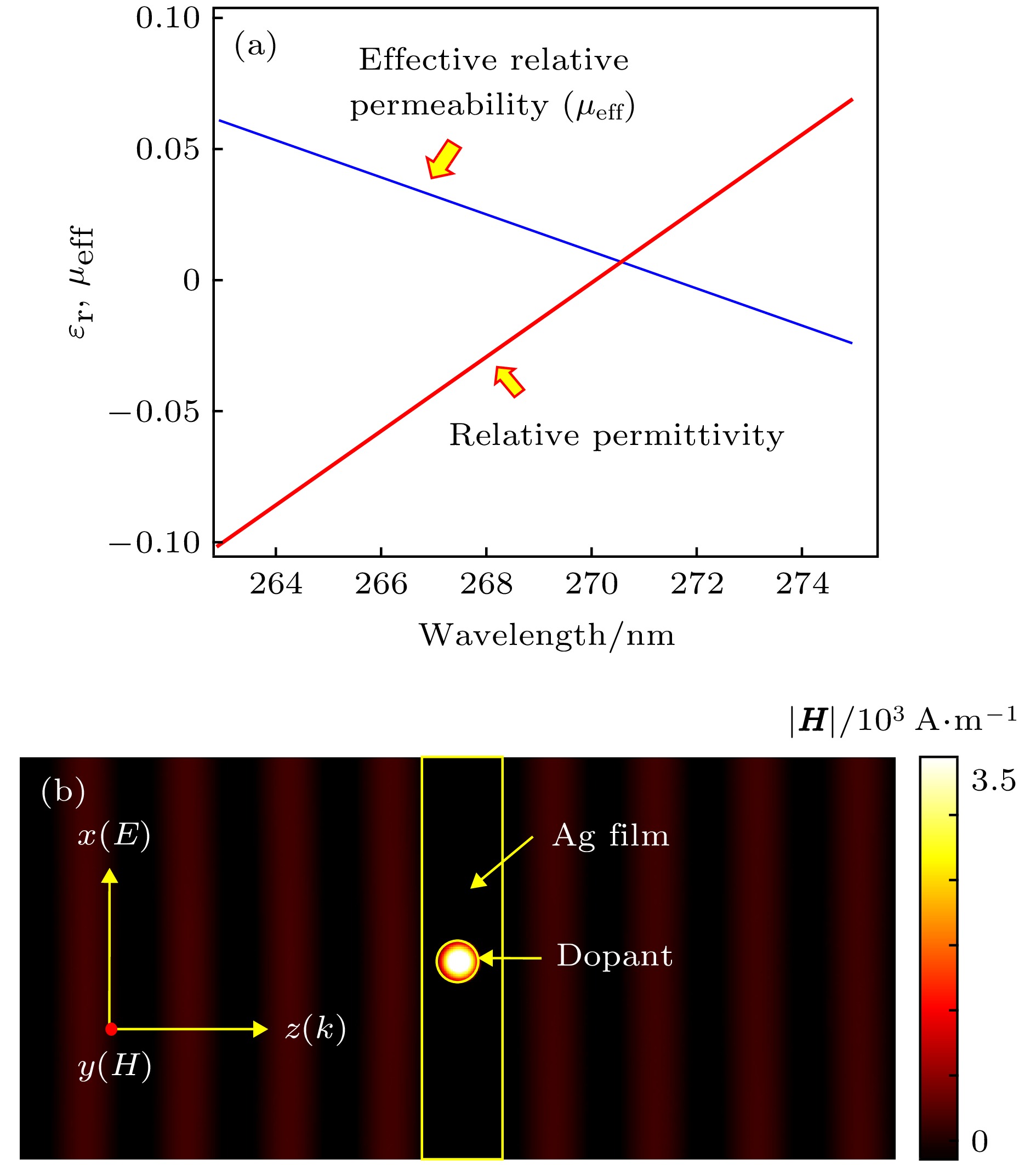 图 5 265—275 nm紫外光波段点火器件的计算分析与仿真验证 (a) 265—275 nm波段银的相对介电常数以及掺杂介质的银薄膜的等效磁导率计算曲线; (b) 270 nm波长掺杂介质的银薄膜的磁场分布仿真结果
Figure5. Analysis and simulation of ignition device at wavelength of 270 nm: (a) The relative permittivity of silver film (red line) and the effective relative permeability of silver film filled with dielectric dopant at wavelength of 263 nm to 275 nm (blue line); (b) the simulation result of magnetic field in silver film filled with dielectric dopant at wavelength of 270 nm (rd/λ0 = 0.2261, εrd = 3).
