全文HTML
--> --> -->因为用Ce取代Nd2Fe14B中的Nd将会导致磁体的磁晶各向异性降低, 所以人们希望能找到有效的方法来提高Ce磁体的矫顽力. 早期研究[10-13]大多采用传统的粉末冶金工艺来制备Ce磁体, 但这种工艺下生产的磁体表现出比较差的磁性能. 经过长期的探索, 已经证明速凝(SC) + 氢 破(HD) + 气流磨(JM)工艺流程可以有效地使Ce磁体获得更好的磁性能[14]. 近年来, 李卫团队[15-19]发明了双主相法, 通过该方法制备的Ce磁体可具有明显高于单主相法制得磁体的矫顽力.
除了工艺技术方面的创新外[20,21], 研究者们还进行了许多关于Ce磁体的模拟计算[22,23]. 微磁学研究[24]已经证明, 在四种含Ce单晶粒结构的比较中, 当晶粒总Ce含量相同时, 核((Nd, Ce)2Fe14B)-壳(Nd2Fe14B)型晶粒通常具有最高的矫顽力. 本文围绕该种核壳模型, 选择核的成分为(Nd0.7, Ce0.3)2Fe14B(0.7与0.3表示Nd与Ce占晶粒总稀土元素的原子百分比分别为70 at.%和30 at.%), 通过微磁学模拟方法, 在纳米尺度深入探究了核的尺寸、壳层厚度及壳层分布对晶粒矫顽力的影响, 并从理论层面解释了矫顽力变化的原因. 本文旨在通过模拟计算, 提供一种具有较高矫顽力的晶粒结构, 为实验及实际生产提供一定的理论支持及借鉴帮助.
对于本文所探讨的单晶粒核((Nd0.7, Ce0.3)2Fe14B)-壳(Nd2Fe14B)型模型, 室温下的内禀磁性参数选择如下: 对于壳层的成分Nd2Fe14B, 磁晶各向异性常数K1 = 4.5 MJ/m3, 饱和磁化强度Ms = 1281.5 kA/m, 交换积分常数A = 12.5 pJ/m[25]; 对于(Ndx, Ce1–x)2Fe14B, 假设其K1, Ms和A与Nd和Ce的原子百分比一致, 因为对于Ce2Fe14B, K1 = 1.5 MJ/m, Ms = 931 kA/m, A = 5 pJ/m[26], 所以对于核的成分(Nd0.7, Ce0.3)2Fe14B, 根据Nd与Ce所占总稀土元素的原子百分比分别为70%与30%, 其K1 = 4.5 × 0.7 + 1.5 × 0.3 = 3.6 MJ/m3, Ms = 1281 × 0.7 + 931 × 0.3 = 1176 kA/m, A = 12.5 × 0.7 + 5 × 0.3 = 10.25 pJ/m. 根据畴壁宽度lw的计算公式((1)式)及静磁交换长度


3.1.保持壳层厚度不变, 核的尺寸对矫顽力的影响
以壳层均匀包覆于核的四周的核((Nd0.7, Ce0.3)2Fe14B)-壳(Nd2Fe14B) 立方体模型为研究对象. 如图1所示, 将壳层厚度t设定为常数(比如t = 6 nm), 核的边长设定为变量x nm, 探究随着核的尺寸增加, 矫顽力的变化规律.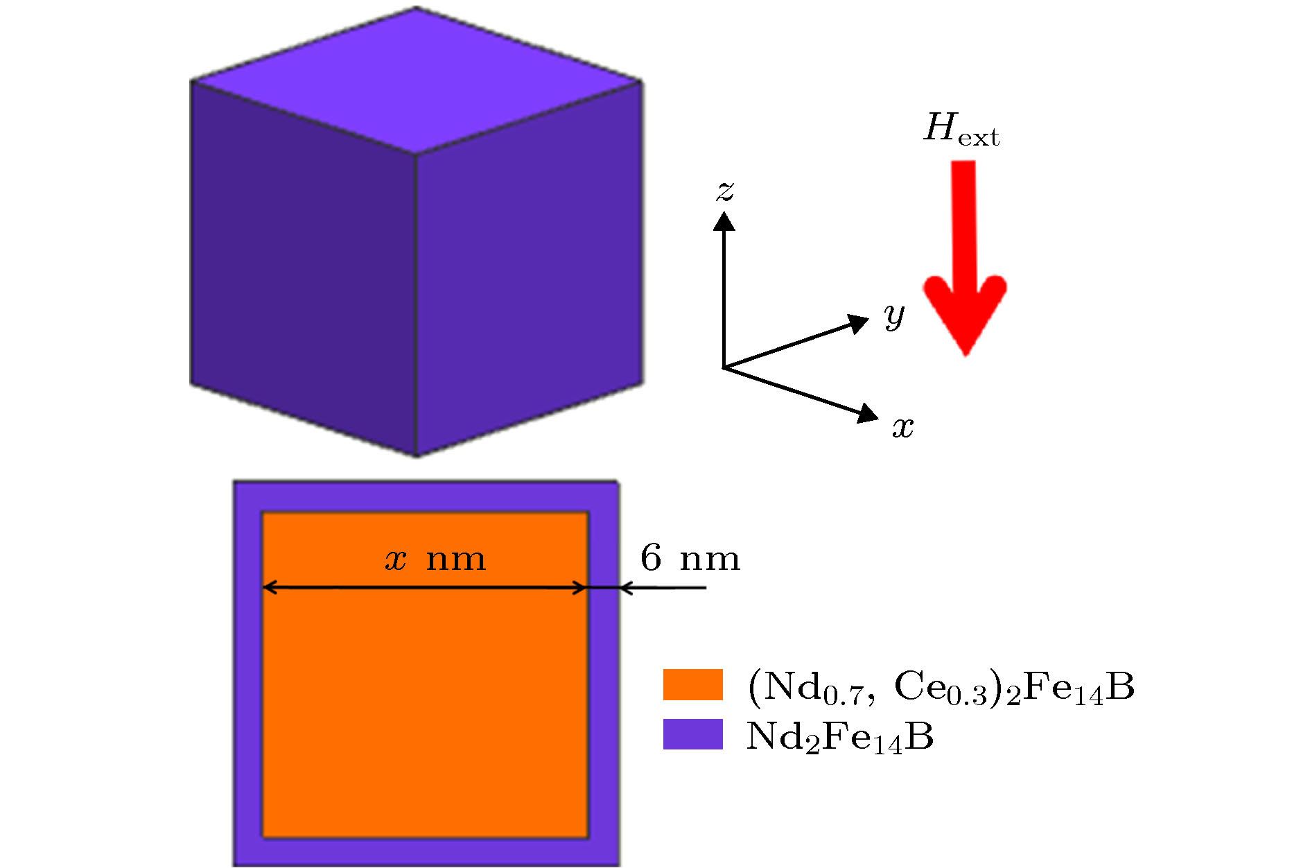 图 1 壳层厚度为常数6 nm, 核的尺寸为变量的核((Nd0.7, Ce0.3)2Fe14B)-壳(Nd2Fe14B)模型
Figure1. The illustration of core ((Nd0.7, Ce0.3)2Fe14B) - shell (Nd2Fe14B) model of which the shell thickness is a constant of 6 nm while the core size is variable.
如图2(a)所示, 当壳层厚度保持为2 nm时, 核的尺寸越大, 矫顽力越小. 当将壳层厚度增加2或4 nm, 即壳层厚度保持为4或6 nm时, 随着核的尺寸增加, 矫顽力依然呈现逐渐降低的趋势.
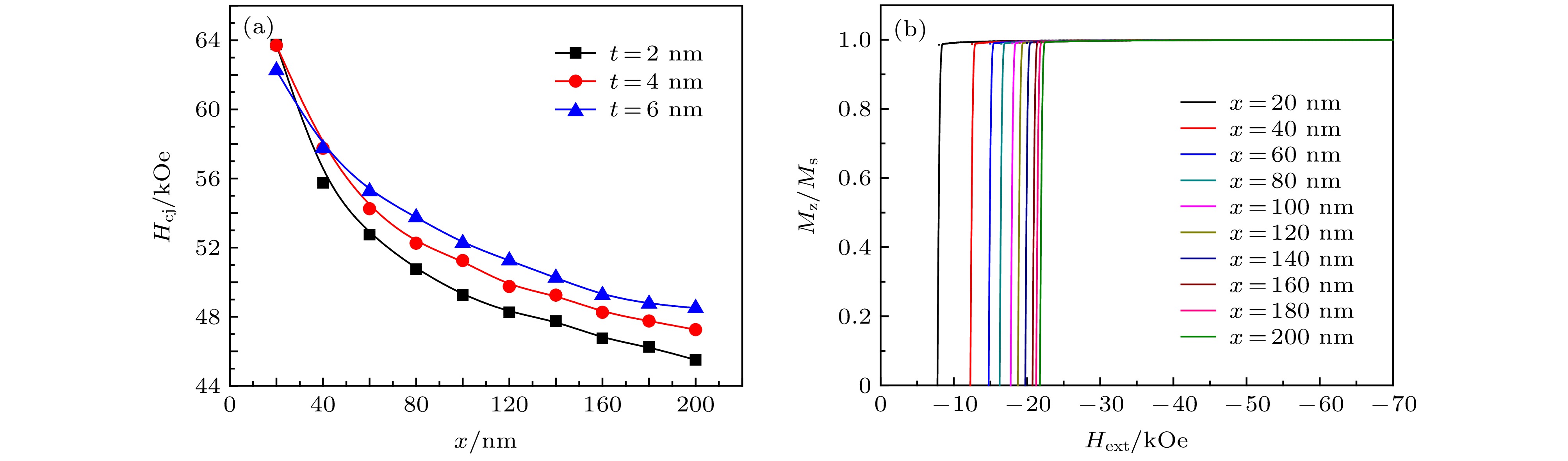 图 2 (a) 矫顽力随核的尺寸(边长x)的变化规律; (b) t = 6 nm时不同核尺寸(边长x)的晶粒的退磁曲线
Figure2. (a) The relevance of the coercivity to the core size (side length x); (b) the demagnetization curves of grains with different core size (side length x) when t = 6 nm.
以壳层厚度t = 6 nm为例, 讨论矫顽力逐渐降低的原因. 图2(b)反映了随着外场增加, t = 6 nm时不同核尺寸的晶粒易轴方向磁化强度的变化. 一方面通过计算发现(如表1所列), 在壳层厚度不变的情况下, 核的尺寸增加会导致晶粒的总Ce含量明显地增加. 因为Ce2Fe14B的磁晶各向异性场比Nd2Fe14B小[16], 所以Ce含量的增加使得晶粒平均磁晶各向异性场出现明显降低的趋势. 我们知道, 晶粒的磁晶各向异性场具有使磁矩保持初始方向而不被轻易翻转的作用, 因此, 晶粒平均磁晶各向异性场的降低将导致晶粒的磁矩在较小的外场作用下即发生翻转, 从而矫顽力降低.
| Core size(x)/nm | Total Ce content/at.% | Average K1 /MJ·m–3 | Average Ms /kA·m–1 | Average HA /kA·m–1·kOe–1 |
| 20 | 7.32 | 4.28 | 1255.37 | (5428.72)/(68.2) |
| 40 | 13.65 | 4.09 | 1233.21 | (5277.48)/(66.3) |
| 60 | 17.36 | 3.98 | 1220.24 | (5189.92)/(65.2) |
| 80 | 19.73 | 3.91 | 1211.96 | (5134.20)/(64.5) |
| 100 | 21.35 | 3.86 | 1206.26 | (5094.40)/(64.0) |
| 120 | 22.54 | 3.82 | 1202.11 | (5062.56)/(63.6) |
| 140 | 23.44 | 3.80 | 1198.96 | (5038.68)/(63.3) |
| 160 | 24.15 | 3.78 | 1196.48 | (5022.76)/(63.1) |
| 180 | 24.72 | 3.76 | 1194.48 | (5006.84)/(62.9) |
| 200 | 25.19 | 3.74 | 1192.84 | (4998.88)/(62.8) |
表1壳层厚度保持为6 nm时, 不同核尺寸(边长)的晶粒的总Ce含量及内禀磁性参数
Table1.The total Ce content and intrinsic magnetic parameters of the grain with the same shell thickness 6 nm but different core size (side length).
另一方面, 综合比较每种核尺寸的晶粒的退磁过程, 如图3所示, 可以发现, 在相同的外场下, 晶粒的核尺寸越大, 晶粒的总体积越大, 其总退磁能Ed越大. 因为退磁场有利于磁体反磁化, 而退磁能是退磁场与磁体内磁化强度的相互作用能, 所以, 晶粒总退磁能的增大是导致矫顽力减小的又一重要原因.
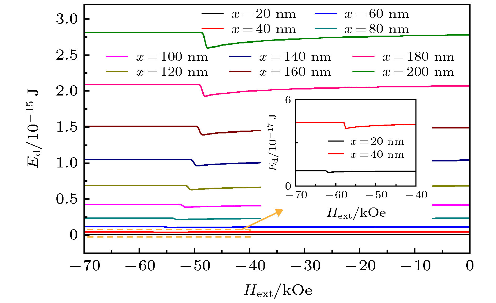 图 3 不同核尺寸(边长)的晶粒总退磁能Ed的比较
Figure3. Comparisons of the total demagnetization energy Ed of grains with various core size (side length).
2
3.2.保持核的尺寸不变, 壳层厚度对矫顽力的影响
以核((Nd0.7, Ce0.3)2Fe14B)-壳(Nd2Fe14B) 立方体模型为研究对象(图4), 设定核的尺寸为常数(比如200 nm × 200 nm × 200 nm), 壳层厚度t设定为变量, 探究壳层厚度的变化对单晶粒磁体矫顽力的影响.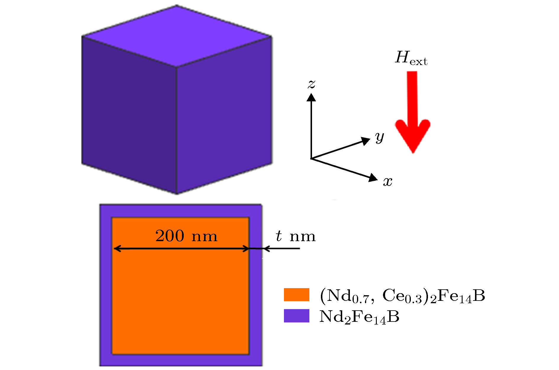 图 4 核的尺寸为常数200 nm × 200 nm × 200 nm, 壳层厚度t为变量的核((Nd0.7, Ce0.3)2Fe14B)-壳(Nd2Fe14B)模型
Figure4. Illustration of core ((Nd0.7, Ce0.3)2Fe14B) - shell (Nd2Fe14B) model of which the core size is a constant of 200 nm × 200 nm × 200 nm while the shell thickness t is variable.
如图5(a)所示, 当核的尺寸保持为50 nm × 50 nm × 50 nm时, 随着壳层厚度t由2 nm增加至20 nm, 矫顽力先逐渐增加, 并在t = 6 nm时取得最大值, 之后逐渐降低. 当将核的尺寸增加至100 nm × 100 nm × 100 nm甚至200 nm × 200 nm × 200 nm时, 可以发现, 随着壳层厚度的增加, 矫顽力依然呈现先增加后降低的趋势. 接下来, 以核的尺寸为200 nm × 200 nm × 200 nm为例, 讨论随着壳层厚度由2 nm增加至20 nm, 矫顽力先增加后降低的原因. 图5(b)反映了随着外场增加, 核为200 nm × 200 nm × 200 nm时不同壳层厚度的晶粒易轴方向磁化强度的变化.
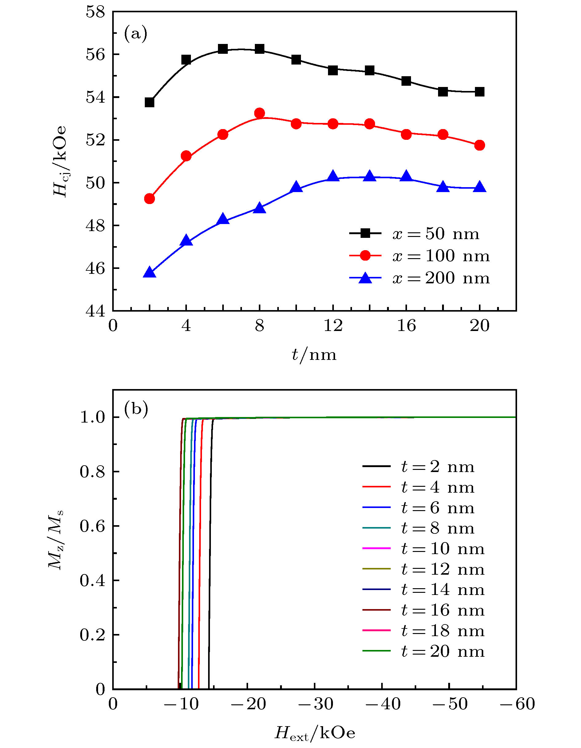 图 5 (a) 不同核尺寸下矫顽力随壳层厚度的变化规律; (b) 核尺寸为200 nm × 200 nm × 200 nm时不同壳层厚度的晶粒的退磁曲线
Figure5. (a) The relevance of the coercivity to the shell thickness; (b) the demagnetization curves of grains with different shell thicknesses when the core size is kept at 200 nm × 200 nm × 200 nm.
在同一外加磁场下, 磁矩会随着时间动态演化, 本节则通过采用时间分辨率模拟的方法来揭示退磁过程中的形核与长大现象. 同样基于该方法, 选择形核点来讨论壳层厚度t影响矫顽力的原因. 以x-z面视图体现, 如图6所示, 不同壳层厚度的晶粒形核点位置不同.
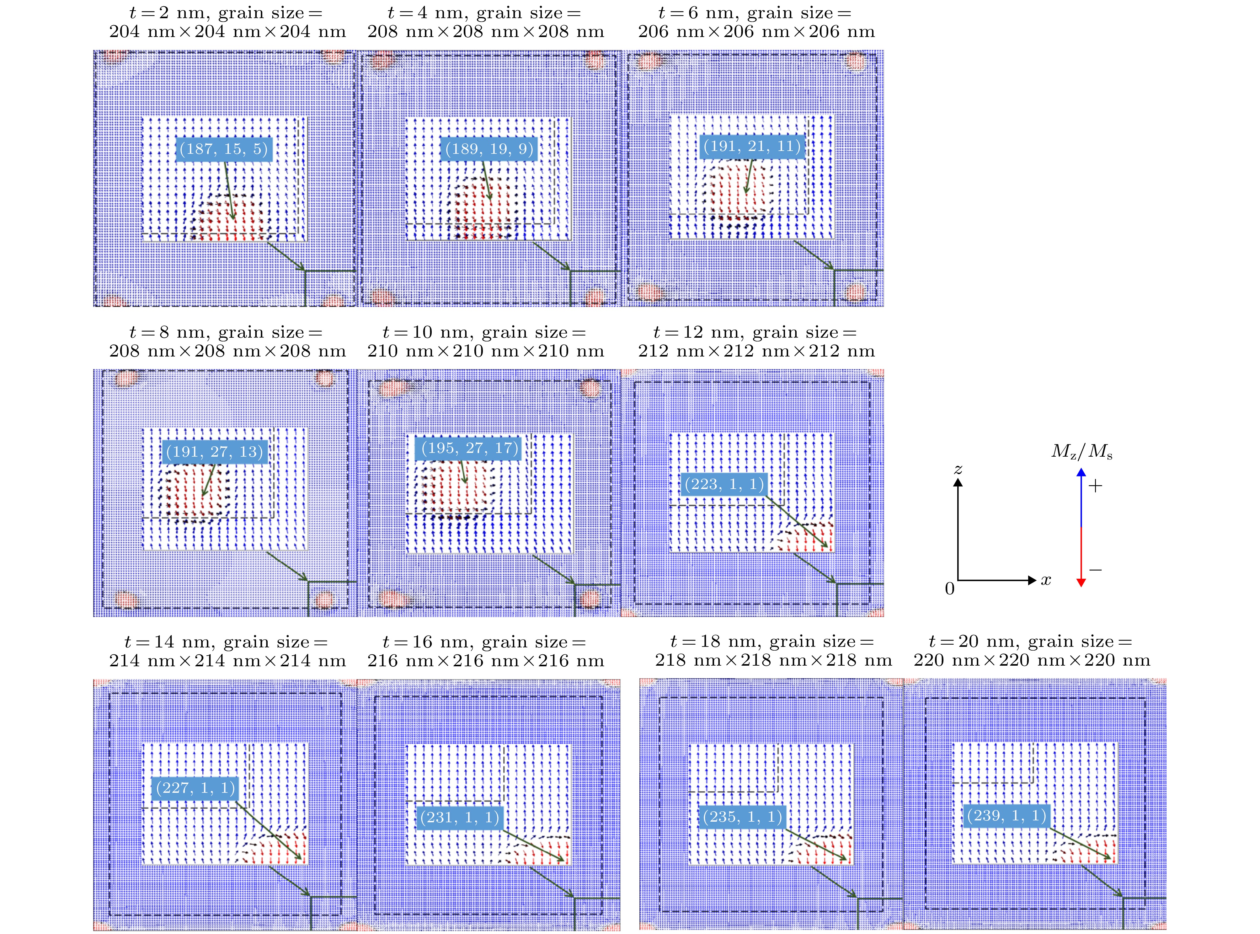 图 6 壳层厚度为2?20 nm时不同的形核点(x-z面视图)(虚线表示核与壳层的边界; 图中放大区域特别标出位置的点表示该模型的形核点; 蓝色箭头代表磁矩与初始磁化方向相同, 即磁矩未反生明显反转, 红色箭头磁矩已经发生反转)
Figure6. Illustration of the nucleation points for t = 2?20 nm (view of x-z plane) (The dotted lines represent the boundary between the core and the shelll; the point in the magnified area specifically indicates the nucleation point of the model; the blue arrow indicates that the magnetic moment is the same as the initial magnetization direction, that is, the magnetic moment is not reflected. Reversal, the magnetic moment of the red arrow has reversed).
根据图6的模拟结果可以发现, 当壳层厚度t为2—10 nm时, 形核点均出现在核壳交界处且属于核的部分; 当壳层厚度t为12—20 nm时, 形核点均出现在壳层顶角处(即晶粒顶角处). 对比图5(a)中矫顽力随壳层厚度的变化, 可以发现, 壳层厚度t为2—10 nm恰好对应矫顽力增加的阶段, 而壳层厚度t为12—20 nm恰好对应矫顽力缓缓降低的阶段. 因此, 根据形核点位置的不同, 可以将t = 2—20 nm分为t = 2—10 nm和t = 12—20 nm两部分讨论矫顽力变化的原因.
1)当t = 2—10 nm时, 形核点位于核壳交界处且属于核的部分, 此时形核点的成分为具有较低磁晶各向异性场的(Nd0.7, Ce0.3)2Fe14B. 如图7所示, 以t = 6 nm的晶粒的磁化反转过程为例进行说明. 因形核发生在核壳边界处, 所以反磁化畴的形核将受到核壳边界效应的影响, 即壳层磁矩与形核点处磁矩的交换耦合作用会阻止反磁化畴形核, 实现退磁需要较大的外场辅助. 随着具有较高磁晶各向异性场的Nd2Fe14B壳层的厚度增加, 核壳边界效应逐渐增强, 实现退磁所需要的外场逐渐增大, 从而矫顽力逐渐增加. 另外, 如表2所列, 随着壳层厚度的增加, 晶粒总Ce含量在逐渐降低, 导致晶粒平均磁晶各向异性场增加. 基于磁晶各向异性场对磁矩维持初始方向的有利作用及对退磁的阻碍作用, 可认为晶粒平均磁晶各向异性场的增加是引起矫顽力增加的另一因素.
| t/nm | Total Ce content/at.% | Average K1/MJ·m–3 | Average Ms/kA·m–1 | Average HA/kA·m–1·kOe–1 |
| 2 | 28.27 | 3.65 | 1182.06 | (4919.28)/(61.8) |
| 4 | 26.67 | 3.70 | 1187.66 | (4959.08)/(62.3) |
| 6 | 25.19 | 3.74 | 1192.84 | (4998.88)/(62.8) |
| 8 | 23.81 | 3.79 | 1197.65 | (5030.72)/(63.2) |
| 10 | 22.54 | 3.82 | 1202.11 | (5062.56)/(63.6) |
| 12 | 21.35 | 3.86 | 1206.26 | (5094.40)/(64.0) |
| 14 | 20.25 | 3.89 | 1210.13 | (5118.28)/(64.3) |
| 16 | 19.22 | 3.92 | 1213.73 | (5150.12)/(64.7) |
| 18 | 18.26 | 3.95 | 1217.09 | (5174.00)/(65.0) |
| 20 | 17.36 | 3.98 | 1220.24 | (5189.92)/(65.2) |
表2核的尺寸保持为200 nm × 200 nm × 200 nm时, 不同壳层厚度t的晶粒的总Ce含量及内禀磁性参数
Table2.The total Ce content and intrinsic magnetic parameters of the grain with the same core size 200 nm × 200 nm × 200 nm but different shell thicknesses t.
 图 7 外场为48.25 kOe (与矫顽力大小相同)时, t = 6 nm晶粒的磁化反转过程(x-z面视图, y = 21 nm)(虚线表示核与壳层的边界; 蓝色箭头代表磁矩与初始磁化方向相同, 即磁矩未反生明显反转, 红色箭头磁矩已经发生反转)
Figure7. The reversal process for t = 6 nm (view of x-z plane at y = 21 nm) under external field of 48.25 kOe (equal to the coercivity) (The dotted lines represent the boundary between the core and the shelll; the blue arrow indicates that the magnetic moment is the same as the initial magnetization direction, that is, the magnetic moment is not reflected. Reversal, the magnetic moment of the red arrow has reversed).
2)当t = 12—20 nm时, 形核点位于壳层顶角处(即晶粒顶角处), 此时形核点的成分为具有较高磁晶各向异性场的Nd2Fe14B. 如图8所示, 选择t = 16 nm的晶粒的磁化反转过程为例进行说明. 当反磁化畴形核后, 畴壁逐渐由形核点向晶粒内部位移, 最终实现晶粒内所有磁矩的翻转. 结合表2可知, 对于t = 12—20 nm, 壳层厚度的增加依然使得晶粒的平均磁晶各向异性场逐渐增加, 而如图9所示, 壳层厚度的增加也导致晶粒的体积不断增加, 使得晶粒的总退磁能不断增加, 因此可认为, 在该阶段, 退磁能的增加对形核及退磁的促进作用要大于平均磁晶各向异性场的增加对退磁的阻碍作用, 从而导致矫顽力出现缓慢的降低.
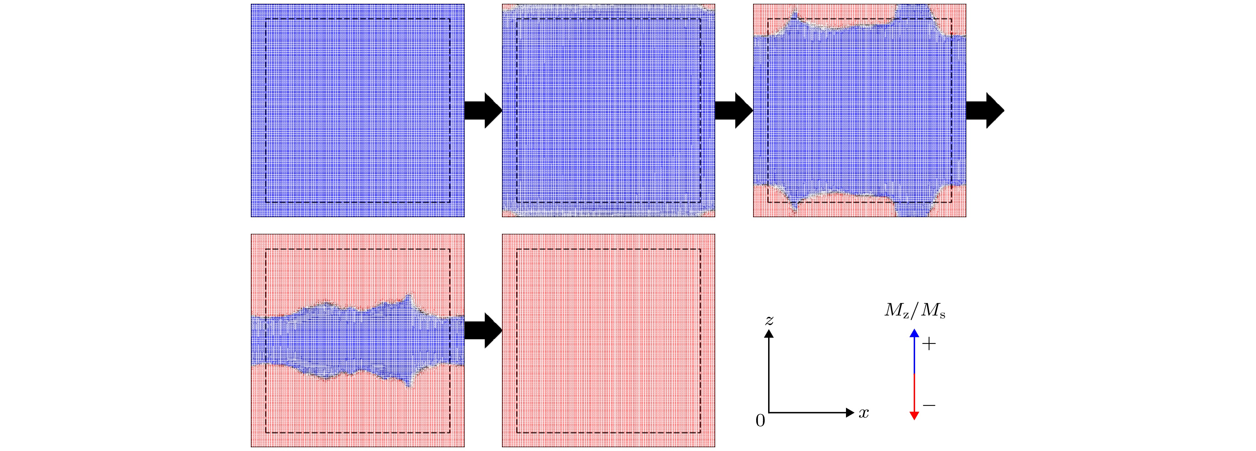 图 8 外场为50.25 kOe (与矫顽力大小相同)时, t = 16 nm晶粒的磁化反转过程(x-z面视图, y = 1 nm)(虚线表示核与壳层的边界; 蓝色箭头代表磁矩与初始磁化方向相同, 即磁矩未反生明显反转, 红色箭头磁矩已经发生反转)
Figure8. The reversal process for t =16 nm (view of x-z plane at y = 1 nm) under external field of 50.25 kOe (equal to the coercivity) (The dotted lines represent the boundary between the core and the shelll; the blue arrow indicates that the magnetic moment is the same as the initial magnetization direction, that is, the magnetic moment is not reflected. Reversal, the magnetic moment of the red arrow has reversed).
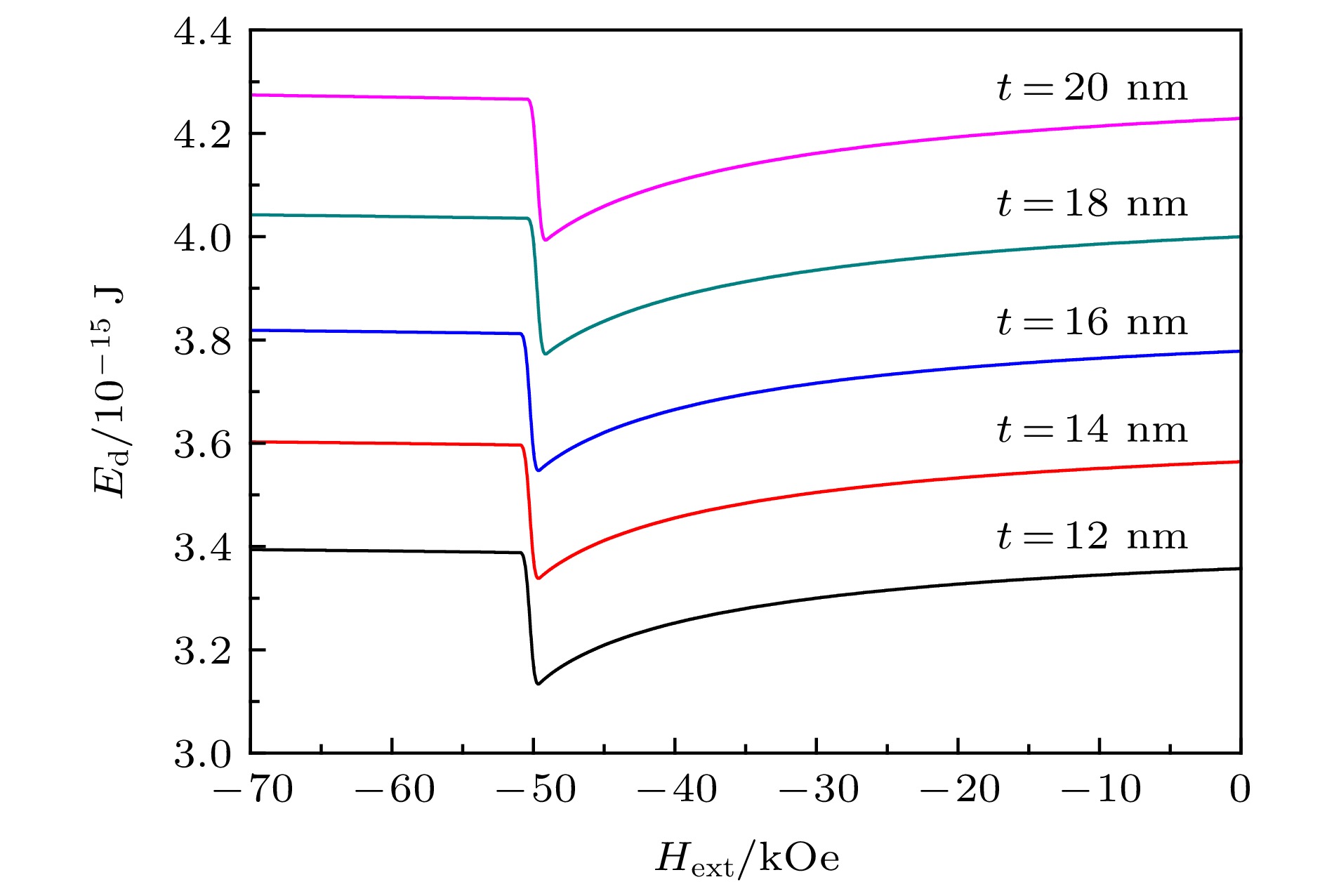 图 9 不同壳层厚度的晶粒总退磁能Ed随外场的变化
Figure9. The change of the total demagnetization energy Ed for grains with different shell thicknesses under varying external field.
对于核尺寸为200 nm × 200 nm × 200 nm的晶粒而言, t = 12—20 nm时的矫顽力普遍大于t = 2—10 nm时的矫顽力, 可认为主要原因是t = 12—20 nm的晶粒形核点处的磁晶各向异性场高于t = 2—10 nm的晶粒形核点. 而对于核尺寸为50以及100 nm的晶粒而言, 会出现处于下降阶段的矫顽力小于处于上升阶段的矫顽力的情况, 归其原因, 可认为是随壳层厚度增加, 退磁能增加促进退磁的效应强于形核点处高磁晶各向异性场阻碍退磁的效应.
2
3.3.保持壳层体积不变, 壳层分布对矫顽力的影响
本节进行比较的6种核((Nd0.7, Ce0.3)2Fe14B)-壳(Nd2Fe14B)模型如图10所示, 核的尺寸均相同, 探究在壳层体积相同的条件下, 不同的壳层分布对矫顽力的影响. 前两节的探究已经表明, 相同的探究条件下, 较小尺寸的模型与较大尺寸的模型具有相同的规律, 比如3.1节中, 随着壳层厚度增加, 核的尺寸为50 nm × 50 nm × 50 nm的晶粒与核的尺寸为200 nm × 200 nm × 200 nm的晶粒在矫顽力方面均呈现先增加后降低的趋势, 本节中将核的尺寸设定为较小值40 nm × 40 nm × 40 nm, 同时为了保证计算精度, 将网格尺寸设定为1 nm × 1 nm × 1 nm.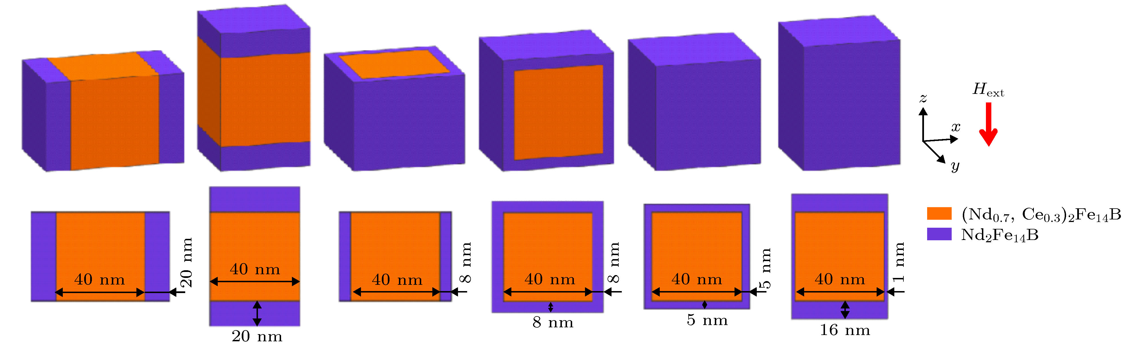 图 10 6种核((Nd0.7, Ce0.3)2Fe14B)-壳(Nd2Fe14B)模型, 从左到右: ax型, 壳层只分布在核的x面(即与x轴垂直的面), 两面各一半; az型, 壳层只分布在核的z面(即与z轴垂直的面), 两面各一半; bxy型, 壳层均匀分布在核的x面和y面; bxz型, 壳层均匀分布在核的x面和z面; c型, 壳层均匀分布在核的x面、y面、z面(即均匀包覆); c'型, 壳层在核的x面和y面的厚度均为1 nm, 在核的z面厚度随壳层总体积可变 (图中标示尺寸以Vshell/Vgrain ≈ 50%为例)
Figure10. Illustration of six types of core ((Nd0.7, Ce0.3)2Fe14B)-shell (Nd2Fe14B) model, from left to right: ax type, the shell is evenly distributed on the two x-planes (the plane perpendicular to the x-axis) of the core; az type, the shell is evenly distributed on the two z-planes (the plane perpendicular to the z-axis) of the core; bxy type, the shell is evenly distributed on the x-planes and the y-planes of the core; bxz type, the shell is evenly distributed on the x-planes and the z-planes of the core; c type, the shell is evenly distributed on the x-planes, y-planes and the z-planes of the core (evenly distributed around the core); c' type, both the shell thicknesses for the x-planes and the y-planes of the core are 1 nm, and the shell thickness for the z-planes of the core is variable with changing total shell volume (The size shown in the figure takes Vshell/Vgrain ≈ 50% as an example).
如图11所示, 横坐标为壳层体积占晶粒总体积的百分比, 多组纵向比较发现, 在该模拟条件下, 当Vshell/Vgrain相同时, az型晶粒的矫顽力始终最大, ax型晶粒的矫顽力始终最小, c型(壳层均匀包覆核)结构并非使晶粒矫顽力达到最大的最优结构.
 图 11 相同壳层体积下6种核壳结构矫顽力的比较
Figure11. Comparisons for the coercivity of six types of core-shell grain structure with the same shell volume.
以Vshell/Vgrain ≈ 50%为例, 探究6种结构晶粒矫顽力不同的原因. 采用时间分辨率的模拟方法, 可得到晶粒的反磁化过程. 从x-z面视图角度, 图12(a)—(f)分别展示了az型、c' 型、bxz型、c型、bxy型、ax型的晶粒的退磁过程.
 图 12 Vshell/Vgrain ≈ 50%时, 6种晶粒的磁化反转过程图(x-z面视图) (a) az型(x-z面位置: y = 0.5 nm; 外场为59.75 kOe, 与矫顽力大小相同); (b) c'型(x-z面位置: y = 0.5 nm; 外场为59.25 kOe, 与矫顽力大小相同); (c) bxz型(x-z面位置: y = 0.5 nm; 外场为58.75 kOe, 与矫顽力大小相同); (d) c型(x-z面位置: y = 0.5 nm; 外场为57.75 kOe, 与矫顽力大小相同); (e) bxy型(x-z面位置: y = 18.5 nm; 外场为54.75 kOe, 与矫顽力大小相同); (f) ax型(x-z面位置: y = 0.5 nm; 外场为51.25 kOe, 与矫顽力大小相同)
Figure12. The reversal magnetization processes of six types of grains when Vshell/Vgrain ≈ 50% (view of x-z plane): (a) az type (x-z plane position: y = 0.5 nm; external field is 59.75 kOe, same as coercive force); (b) c' type (x-z plane position: y = 0.5 nm; external field is 59.25 kOe, and the coercive force is the same); (c) bxz type (x-z plane position: y = 0.5 nm; the external field is 58.75 kOe, which is the same as the coercive force); (d) c type (x-z plane position: y = 0.5 nm; the external field is 57.75 kOe, which is the same as the coercive force; (e) bxy type (x-z plane position: y = 18.5 nm; the external field is 54.75 kOe, which is the same as the coercive force); (f) ax type (x-z plane position: y = 0.5 nm; the external field is 51.25 kOe, which is the same as the coercive force).
根据形核点位置的不同, 将以上6种晶粒分两部分讨论, 第一部分为az型、c' 型、bxz型及c型, 这4种晶粒的形核点均出现在壳层顶角处(晶粒顶角处), 而第二部分为bxy型和ax型, 这两种晶粒的形核点均出现在核部z面的棱边处. 图11的结果表明, 第一部分晶粒的矫顽力均大于第二部分晶粒的矫顽力, 主要原因是第一部分晶粒的形核点成分为Nd2Fe14B, 具有较高的磁晶各向异性, 从而形核场较高, 矫顽力更大, 而第二部分晶粒的形核点成分为(Nd0.7Ce0.3)2Fe14B, 具有较低的磁晶各向异性, 形核场较低, 矫顽力相对较低.
图13为第一部分4种晶粒的退磁曲线, 关于该4种晶粒, 其矫顽力大小为: az型 > c' 型 > bxz型 > c型. 因其形核点均位于壳层顶角处(晶粒顶角处), 所以可从形核点处z轴方向的退磁场以及晶粒总退磁能的角度, 综合分析其矫顽力出现如此差别的原因. 如图14所示, 随着外场增加, 该4种晶粒形核点处退磁场的绝对值或晶粒的总退磁能的大小关系始终为: az型 < c' 型 < bxz型 < c型. 因为较大的退磁场或较大的退磁能均对退磁起到促进作用, 所以合理解释了该4种晶粒矫顽力不同的原因.
 图 13 4种晶粒的退磁曲线
Figure13. The demagnetization curves for four types of grains.
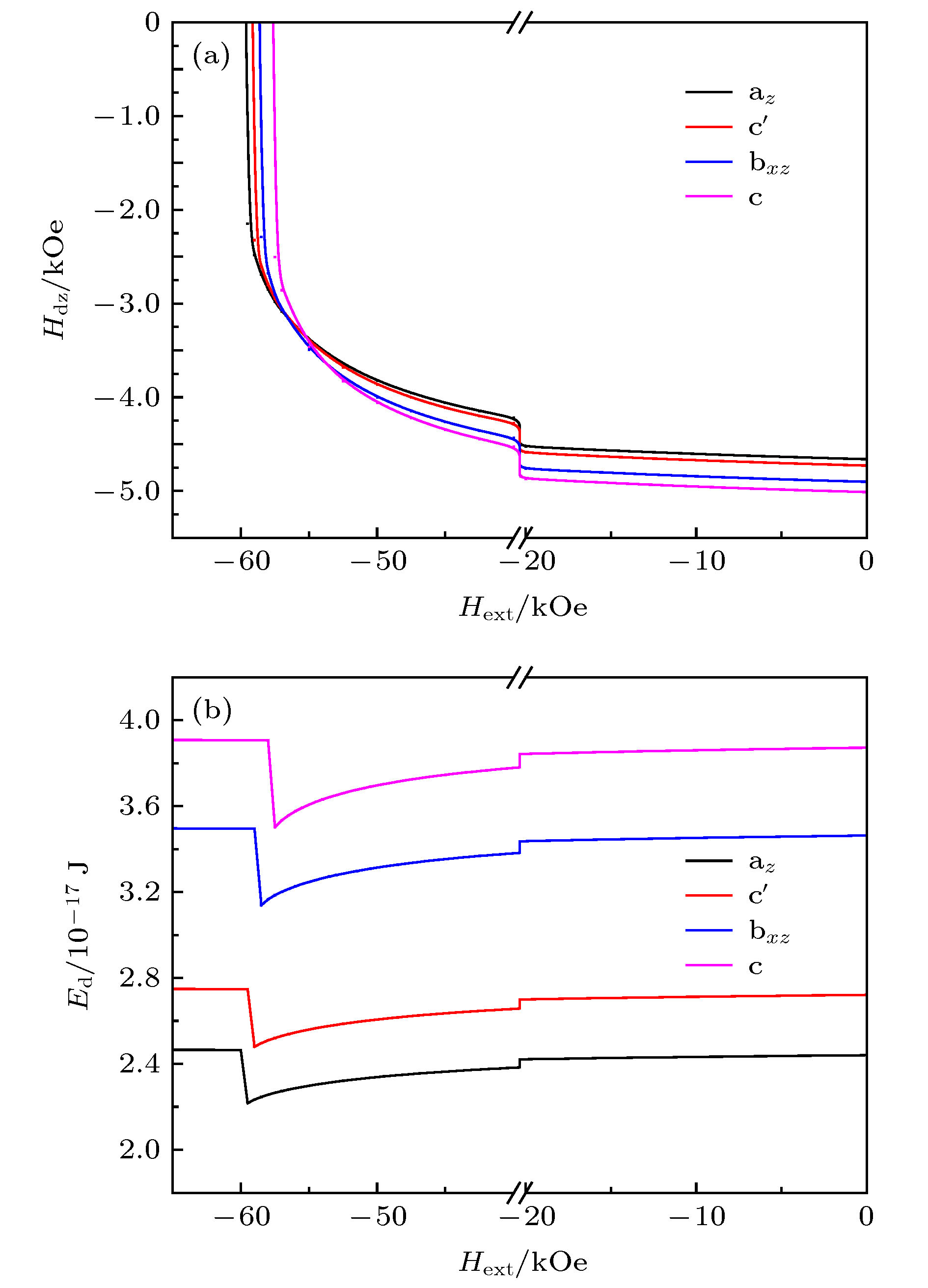 图 14 4种晶粒 (a) 形核点处z轴方向退磁场Hdz的比较; (b) 总退磁能Ed的比较
Figure14. (a) Comparisons for the demagnetization field in z-axis direction Hdz of the nucleation points; (b) the total demagnetization energy Ed of four types of grains.
关于第二部分的两种晶粒, 其形核点均出现在核的z面棱边处, 综合图10的模型图及图12(e)与图12(f)的形核图可知, bxy型晶粒核部与壳层的接触面积要大于ax型晶粒, 另外, bxy型晶粒的形核点与壳层相距较近, 而ax型晶粒形核点与壳层相距较远. 两方面因素共同说明: bxy型晶粒壳层磁矩与形核点处磁矩的交换相互作用要强于ax型晶粒, 从而导致bxy型晶粒形核点处的磁矩更难以翻转, 实现形核及退磁需要更大的外场辅助, 因此矫顽力更大.
1) 保持壳层厚度不变, 矫顽力随核的尺寸增加而降低. 主要原因是核的尺寸增加导致晶粒平均各向异性场降低以及晶粒总退磁能升高, 使得晶粒在较小的外场下即可发生反磁化行为.
2) 保持核的尺寸不变, 矫顽力随壳层厚度增加呈现先增加后降低的趋势. 从形核点位置分析, 前期矫顽力增加的原因是, 形核点处于核壳交界且属于核的部分, 随壳层厚度增加, 壳层磁矩与形核点处磁矩的交换相互作用增强, 需要更大的外场辅助实现形核. 后期矫顽力降低的原因是, 形核点处于壳层顶角(晶粒顶角), 壳层厚度的增加使得晶粒总退磁能增加, 从而在较小外场下即可形核.
3) 保持核的尺寸及壳层体积不变, 壳层仅均匀分布于核的两个z面时矫顽力最大. 主要原因是形核点处于壳层顶角(晶粒顶角), 磁晶各向异性场相对更大, 且形核点处的退磁场较小.
