全文HTML
--> --> -->
由于磁共振信号大小与探测背景场直接相关, 传统磁共振探测依靠天然地磁场

相比于信号压制方法, 应用于地面磁共振领域的信号增强方法较少. 2015年, Grombacher和Knight[23]首次提出, 调节发射频率形成偏振频率环, 能够有效增大探测激发范围, 从而增强磁共振信号. 该方法操作简单, 能够有效提升磁共振信号1—2倍, 但对于地磁场分布不均匀情况误差较大. 随后, Lin等[24]通过在传统交流激发脉冲前施加直流预极化场, 取得大幅度的信号提升, 但由于预极化场在地下传播范围较浅, 且信号提升与直流电流大小直接相关, 现有技术难以实现大深度范围内地面磁共振探测. 为进一步提升信号幅度、扩展探测范围, Grunewald等[25]于2016年首次将绝热脉冲概念引入地面磁共振领域. 作为磁共振信号增强方法的一种, 该方法常用于实验室、测井磁共振领域[26-28], 通过满足绝热条件的扫频脉冲, 能够有效增大横向激发磁化强度, 提升单次激发效率, 从而增大信号. 但相比于传统发射方式, 绝热脉冲发射必须保证连续变幅变频, 对仪器系统要求较高. 且其激发过程复杂, 发射波形各个参数均对信号提升幅度有直接影响, 建模计算量极大.
针对以上问题, 本文从传统地面磁共振正演理论出发, 结合绝热激发原理, 进一步讨论了绝热脉冲建模过程; 引入布洛赫方程, 推导激发横向磁化强度的分布, 并通过插值计算, 实现了高效正演响应模型构建. 此外, 为了获得最优的信号提升效果, 基于仿真实验, 比较了不同脉冲调制函数及参数作用下, 绝热半波的激发效率问题. 本文的研究, 将为地面磁共振仪器绝热脉冲的推广提供理论支撑.
2.1.传统地面磁共振原理
在地面磁共振探测中, 探测目标为地下水, 由于静态地磁场


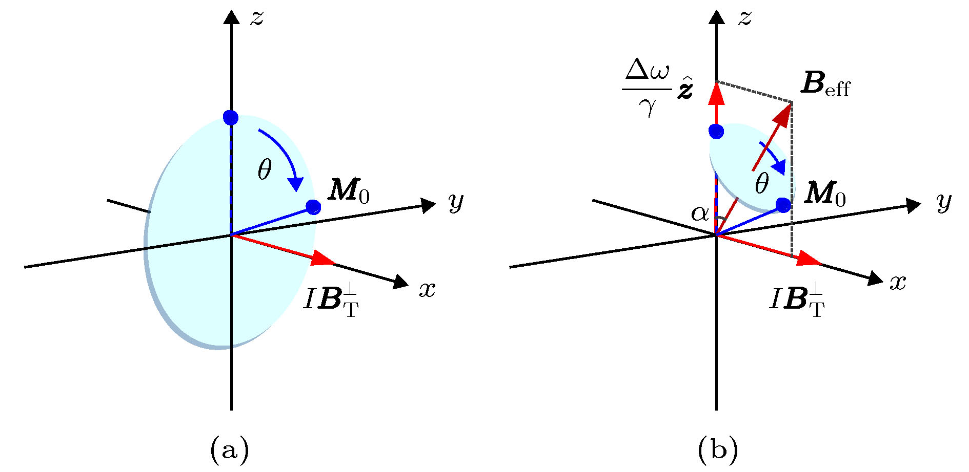 图 1 磁共振激发原理图 (a) 传统方式; (b) 绝热方式
Figure1. Principle of excitation dynamics of magnetic resonance sounding: (a) Traditional type; (b) adiabatic type.


2
2.2.绝热脉冲原理
与传统磁共振固定拉莫尔频率的发射方式不同, 绝热脉冲在发射时采取变频率、幅度的方式[26]. 绝热脉冲最早应用于高场磁共振领域, 通过在拉莫尔频率附近扫频, 使发射电流频率与拉莫尔频率形成频率差, 产生额外的虚拟激发场, 结合变流改变激发场矢量和, 实时控制激发场大小及方向变化, 并在满足“绝热条件”的前提下, 引导磁化强度
如图1(b)所示, 以常见的绝热半波(adiabatic half passage, AHP)为例, 发射初始频率为


 图 2 绝热磁共振激发过程 (a) 发射时序, 红色曲线为发射电流, 蓝色曲线为FID信号; (b) 激发磁场与磁化强度示意图, 深红箭头和蓝色线分别表示激发磁场与磁化强度
Figure2. Excitation process of the adiabatic pulses: (a) The sequence diagram of the transmitting current (red) and FID signal (blue); (b) the relationship of the excitation magnetic field (dark red arrow) and magnetization (blue line).
由于绝热脉冲通过满足“绝热条件”的扫频、变流脉冲改变了磁化强度运动轨迹, 所以, 激发过程中, 横向磁化强度


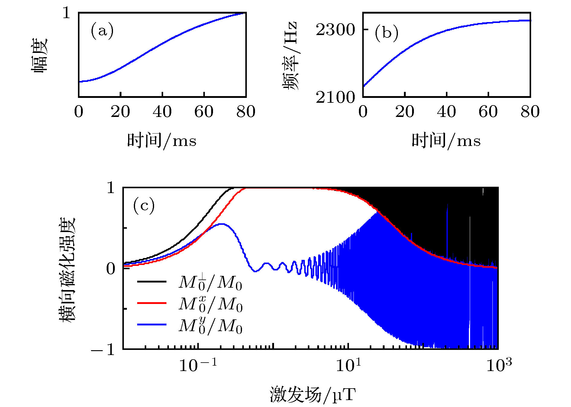 图 3 双曲正切绝热半波横向磁化强度与有效激发磁场关系图(品质因数Q = 30, 脉冲持续时间τ = 80 ms) (a)发射波形实时幅值; (b)频率调制函数; (c)磁化强度x分量、y分量及模值
Figure3. The relationship of transverse magnetization and exciting magnetic based on hyperbolic tangent AHP pulse: (a) The waveform of transmitting current amplitude; (b) its frequency vs. time; (c) magnetization x-component, y-component and real value.
为验证以上参数对绝热脉冲激发效率的影响, 选定中心线圈配置[37]方式(100 m单匝方形的发射线圈、25 m长4匝方形接收线圈)及双曲正切绝热半波, 并应用时间步长法计算不同参数下, 激发磁场与横向磁化强度关系, 探究对应灵敏度核函数分布及正演响应. 为了降低计算量, 数值模拟还引入了插值技术, 即通过计算少量有效交流激发场对应激发横向磁化强度的分布, 插值实现整体地下激发磁化强度快速计算. 本文所有计算与仿真实验均默认拉莫尔频率为2330 Hz, 地磁倾角与偏角分别为60°与0°, 地下半空间电阻率为100 Ω·m.
2
3.1.不同脉冲持续时间影响
根据仿真得到的横向磁化强度与激发磁场大小的关系, 选定1—600 A之间按对数分布的40组脉冲电流, 并设定发射线圈品质因数Q = 30, 计算20—160 ms不同脉冲持续时间下的灵敏度核函数, 其实部、虚部分别如图4和图5所示. 图 4 相同激发电流分布(1—600 A)情况下, 脉冲持续时间τ不同时, 绝热半波对应的灵敏度核函数实部(品质因数Q = 30) (a) τ = 20 ms; (b) τ = 40 ms; (c) τ = 60 ms; (d) τ = 80 ms; (e) τ = 100 ms; (f) τ = 120 ms; (g) τ = 140 ms; (h) τ = 160 ms
Figure4. The real kernel function of adiabatic half-passage pulses for the same excitation current (1–600 A) corresponding to different τ, with quality factor Q = 30: (a) τ = 20 ms; (b) τ = 40 ms; (c) τ = 60 ms; (d) τ = 80 ms; (e) τ = 100 ms; (f) τ = 120 ms; (g) τ = 140 ms; (h) τ = 160 ms.
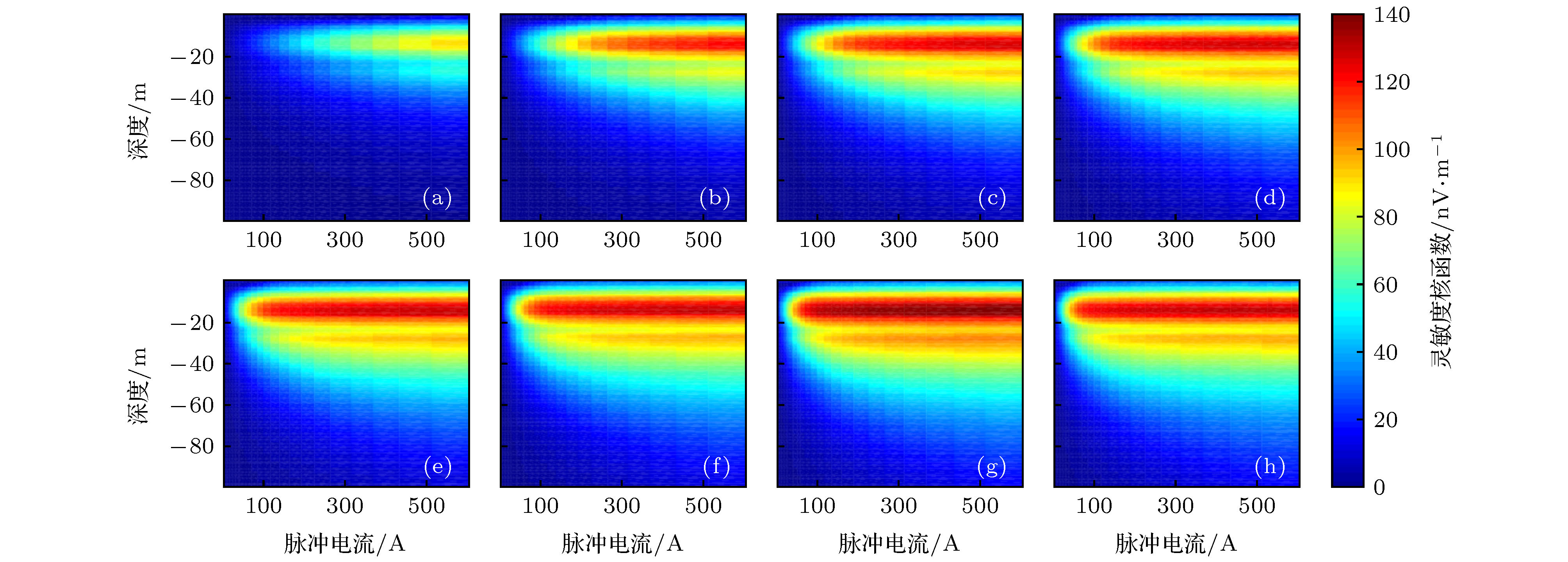 图 5 相同激发电流分布情况下, 脉冲持续时间τ不同时绝热半波对应的灵敏度核函数虚部(品质因数Q = 30) (a) τ = 20 ms; (b) τ = 40 ms; (c) τ = 60 ms; (d) τ = 80 ms; (e) τ = 100 ms; (f) τ = 120 ms; (g) τ = 140 ms; (h) τ = 160 ms
Figure5. The imaginary kernel function of adiabatic half-passage pulses for the same excitation current (1–600 A) corresponding to different τ, with quality factor Q = 30: (a) τ = 20 ms; (b) τ = 40 ms; (c) τ = 60 ms; (d) τ = 80 ms; (e) τ = 100 ms; (f) τ = 120 ms; (g) τ = 140 ms; (h) τ = 160 ms.
由图4可知, 在发射电流与发射线圈品质因数相同的情况下, 随着发射持续时间延长, 灵敏度核函数实部整体呈现减小趋势, 但其主瓣更加集中, 且同一电流对应的探测深度随时间延长而增大. 随着脉冲时间不断增大, 以上趋势逐渐变慢, 最后灵敏度核函数实部几乎不变. 与之相反, 灵敏度核函数虚部随着脉冲发射时间的延长而不断增大, 主瓣外的副瓣也不断加强, 并在140 ms时达到峰值. 而在140 ms后, 灵敏度核函数虚部稍有降低. 综合实部与虚部计算结果, 绝热脉冲与传统脉冲并不完全相同, 发射电流不变的情况下, 增大脉冲持续时间, 并不一定能提升信号响应. 针对本文应用实验配置, 80 ms的发射脉冲能够达到最优的信号增强效果.
本文并没有计算160 ms以上的脉冲持续时间情况. 一方面, 由于仪器充电功率限制, 过长的发射时间将对仪器系统提出更高的要求, 对于进一步实测实验的参考意义较小. 另一方面, 当地下存在磁性介质时, 拉莫尔频率分布并不均匀, 过长的脉冲发射时间, 会积累更大的频率偏振误差. 但根据绝热脉冲原理可以大致预测, 大于160 ms脉冲持续时间的灵敏度核函数情况. 即由于脉冲后期发射频率无限接近于拉莫尔频率, 灵敏度核函数不会有明显变化, 仅其浅层会随着发射时间进一步延长, 在较小范围内振荡.
此外, 本节没有计算不同脉冲持续时间下的正演响应. 这是由于在不同发射时间下, 为保证同一电流范围, 各组实验的脉冲矩分布并不相同, 故难以进行直接对比.
2
3.2.不同脉冲电流与持续时间分布影响
根据仿真得到的横向磁化强度与激发磁场大小关系, 选定0.01—7.3 A·s之间按对数分布的40组脉冲矩, 并设定发射线圈品质因数Q = 30, 计算同一脉冲矩对应不同脉冲电流、持续时间分布对灵敏度核函数及正演结果的影响.由图6和图7可知, 在同一脉冲矩分布条件下, 随着脉冲持续电流延长(对应发射电流缩小), 灵敏度核函数实部分布趋势基本不变, 但在脉冲持续时间小于80 ms时, 其实部峰值随

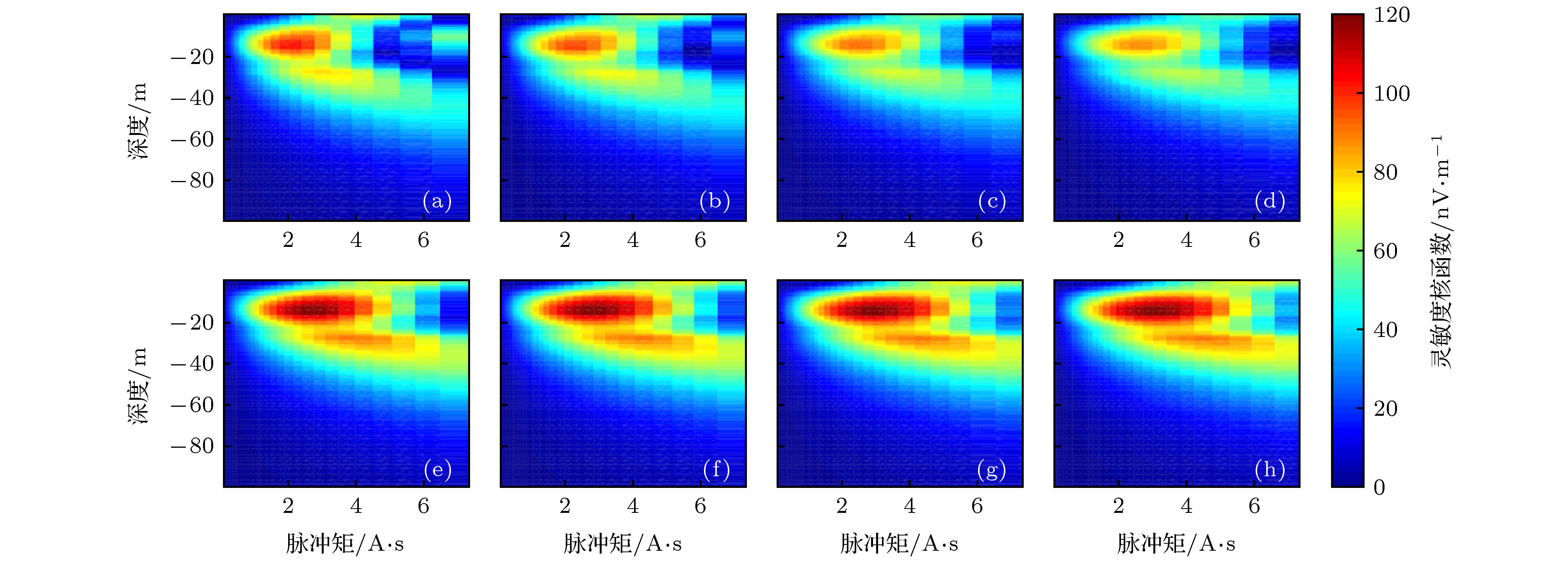 图 6 相同脉冲矩(0.01—7.3 A·s)情况下, 脉冲持续时间τ不同时绝热半波对应的灵敏度核函数实部(品质因数Q = 30) (a) τ = 20 ms, 最大600 A电流; (b) τ = 40 ms, 最大300 A电流; (c) τ = 60 ms, 最大200 A电流; (d) τ = 80 ms, 最大150 A电流; (e) τ = 100 ms, 最大120 A电流; (f) τ = 120 ms, 最大100 A电流; (g) τ = 140 ms, 最大85.7 A电流; (h) τ = 160 ms, 最大75 A电流
Figure6. The real kernel function of adiabatic half-passage pulses for the same pulse moment corresponding to different τ, with quality factor Q = 30: (a) τ = 20 ms with maximum current 600 A; (b) τ = 40 ms with maximum current 300 A; (c) τ = 60 ms with maximum current 200 A; (d) τ = 80 ms with maximum current 150 A; (e) τ = 100 ms with maximum current 120 A; (f) τ = 120 ms with maximum current 100 A; (g) τ = 140 ms with maximum current 85.7 A; (h) τ = 160 ms with maximum current 75 A.
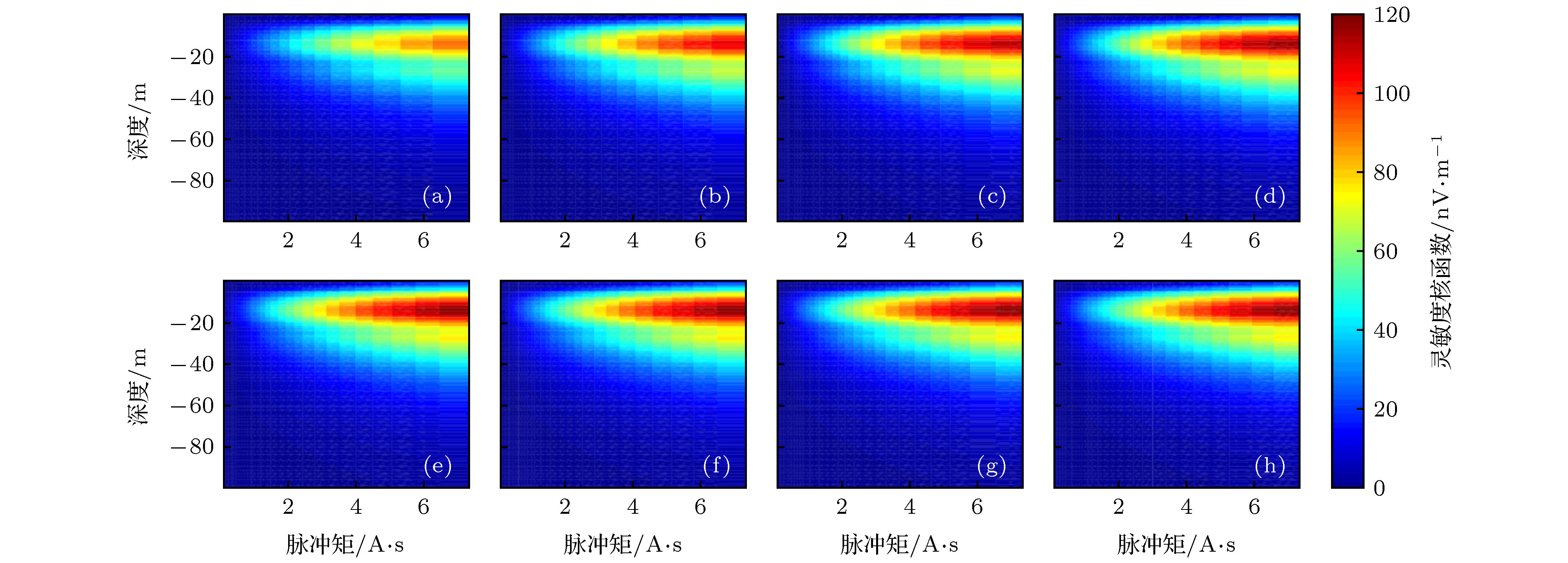 图 7 相同脉冲矩(0.01—7.3 A.s)情况下, 脉冲持续时间τ不同时绝热半波对应的灵敏度核函数虚部(品质因数Q = 30) (a) τ = 20 ms, 最大600 A电流; (b) τ = 40 ms, 最大300 A电流; (c) τ = 60 ms, 最大200 A电流; (d) τ = 80 ms, 最大150 A电流; (e) τ = 100 ms, 最大120 A电流; (f) τ = 120 ms, 最大100 A电流; (g) τ = 140 ms, 最大85.7 A电流; (h) τ = 160 ms, 最大75 A电流
Figure7. The imaginary kernel function of adiabatic half-passage pulses for the same pulse moment corresponding to different τ, with quality factor Q = 30: (a) τ = 20 ms with maximum current 600 A; (b) τ = 40 ms with maximum current 300 A; (c) τ = 60 ms with maximum current 200 A; (d) τ = 80 ms with maximum current 150 A; (e) τ = 100 ms with maximum current 120 A; (f) τ = 120 ms with maximum current 100 A; (g) τ = 140 ms with maximum current 85.7 A; (h) τ = 160 ms with maximum current 75 A.
假设地下存在均匀的10%含水体, 根据灵敏度核函数计算得到正演响应, 如图8所示. 可以看到, 在同一脉冲条件下, 不同的发射时间及电流分布能够达到的信号提升量级基本相似, 但较短的脉冲发射时间配合大发射电流, 能够在浅层取得更大的信号幅度. 随着脉冲发射时间增大, 即相应电流减小, 大脉冲矩对应的深部信号在一定范围内增强; 但若脉冲发射时间过长, 由于发射电流总体较小, 对应激发磁场相对也小, 总体信号提升效果反而变差. 即具体探测时, 还需根据探测目标深度、探测环境及实际探测线圈配置, 确定发射电流幅度与持续时间分布关系. 本文选用的实验配置, 在60 ms发射时间时, 能达到较优的信号增强效果.
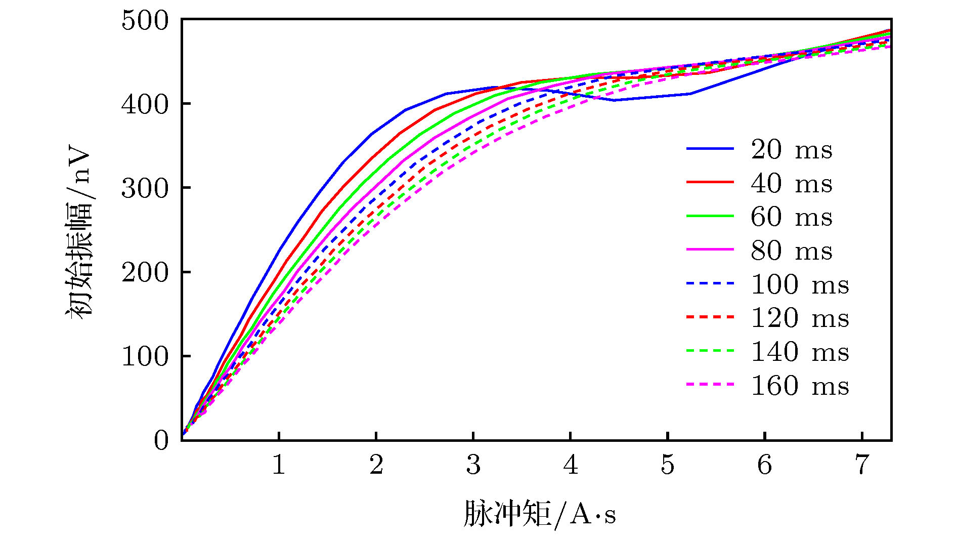 图 8 相同脉冲矩(0.01—7.3 A·s)情况下, 在不同脉冲持续时间及电流条件时绝热半波对应的正演响应(假设地下半空间内存在10%均匀的含水量, 发射线圈的品质因数Q = 30)
Figure8. The forward modeling of adiabatic half-passage pulse for the same pulse moment (0.01–7.3 A·s) with different τ and current. The modeling assume a homogeneous aquifer subsurface with 10% water content, the quality factor Q = 30.
此外, 根据绝热脉冲形成的原理可知, 绝热脉冲发射过程中需始终满足绝热条件. 当脉冲持续时间较小时, 扫频过程更快, 此时如果脉冲电流较小, 尚能满足绝热条件, 所以此时信号提升效果较好; 但随着脉冲电流增大, 扫频过程不能始终绝热条件, 导致该情况下深部信号的提升效果并不理想.
2
3.3.不同发射线圈品质因数影响
根据仿真得到横向磁化强度与激发磁场大小关系, 选定1—600 A之间按对数分布的40组脉冲电流, 并设定脉冲持续时间为80 ms, 计算不同发射线圈品质因数对应的灵敏度核函数及正演结果.由图9(a)—(d)可知, 随着线圈品质因数的增大, 灵敏度核函数实部的主瓣变窄, 其峰值不断增大且对应探测深度变深, 逐渐出现明显的旁瓣. 而灵敏度核函数虚部(图9(e)—(h))变化并不明显, 仅仅是随着品质因数的增大, 幅度上先是略有增加, 随后又稍有下降. 根据灵敏度核函数分布, 计算不同品质因数下的正演信号响应, 并与传统固定拉莫尔频率发射方式对比(脉冲持续时间20 ms), 如图10所示. 品质因数对绝热脉冲激发效果影响较大, 在品质因数较小时, 小激发电流(对应于浅层)的信号提升幅度甚至不如传统方法; 随着品质因数的增大, 对应于各个电流的磁共振信号响应均明显增加, 大激发电流(对应于深部)的信号增强效果尤其明显. 但当品质因数达到一定限度时, 信号幅度不再增加, 且由于此时灵敏度核函数实部除主瓣外, 还存在一定幅度较强的旁瓣, 所以信号初始振幅关于脉冲电流曲线表现出了一定的振荡特性. 即只有选定合理的发射线圈品质因数, 才能保证绝热激发既能明显提升信号幅度, 也能得到较为稳定的响应分布. 最终可以得出结论, 对于本文应用的线圈配置, 品质因数Q = 30情况下, 对应于各个激发电流的信号提升倍数在1.13—16.56范围内, 能够得到最为理想的信号提升效果.
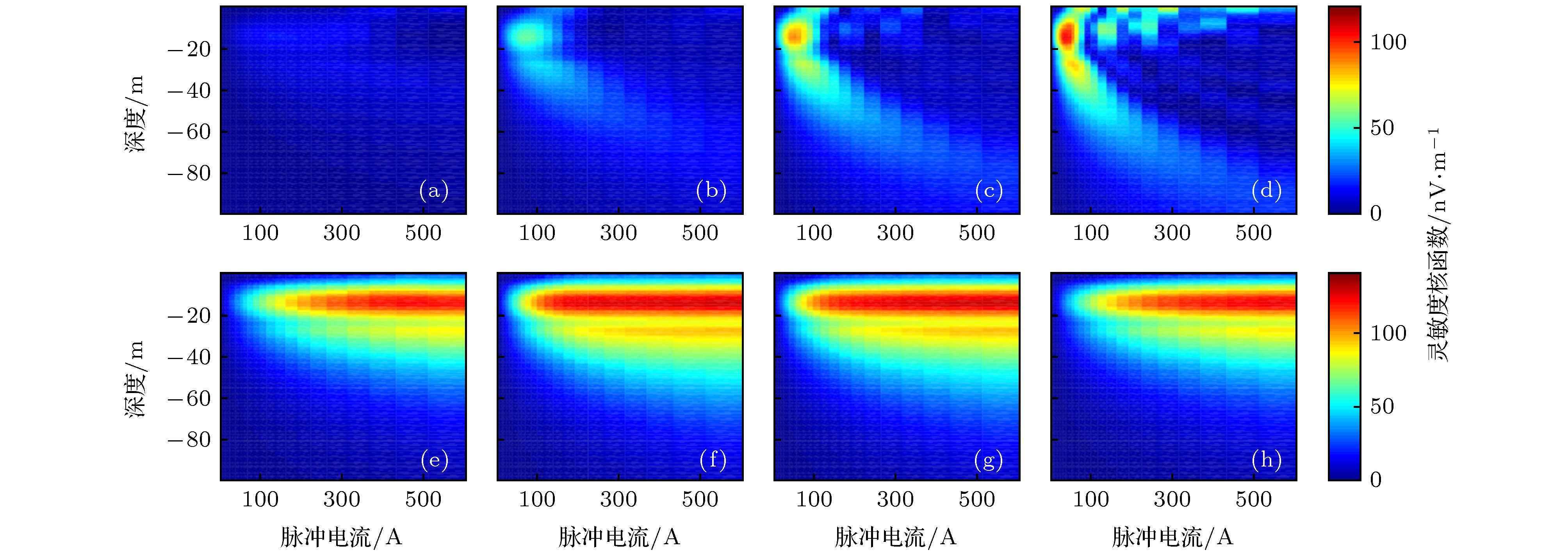 图 9 脉冲持续时间τ = 80 ms, 品质因数Q不同时绝热半波对应的灵敏度核函数的(a), (b), (c), (d)实部和(e), (f), (g), (h)虚部 (a), (e) Q = 10; (b), (f) Q = 20; (c), (g) Q = 30; (d), (h) Q = 40
Figure9. The (a), (b), (c), (d) real and (e), (f), (g), (h) imaginary part of the kernel function of adiabatic half-passage pulses for different quality factor Q with τ = 80 ms: (a), (e) Q = 10; (b), (f) Q = 20; (c), (g) Q = 30; (d), (h) Q = 40.
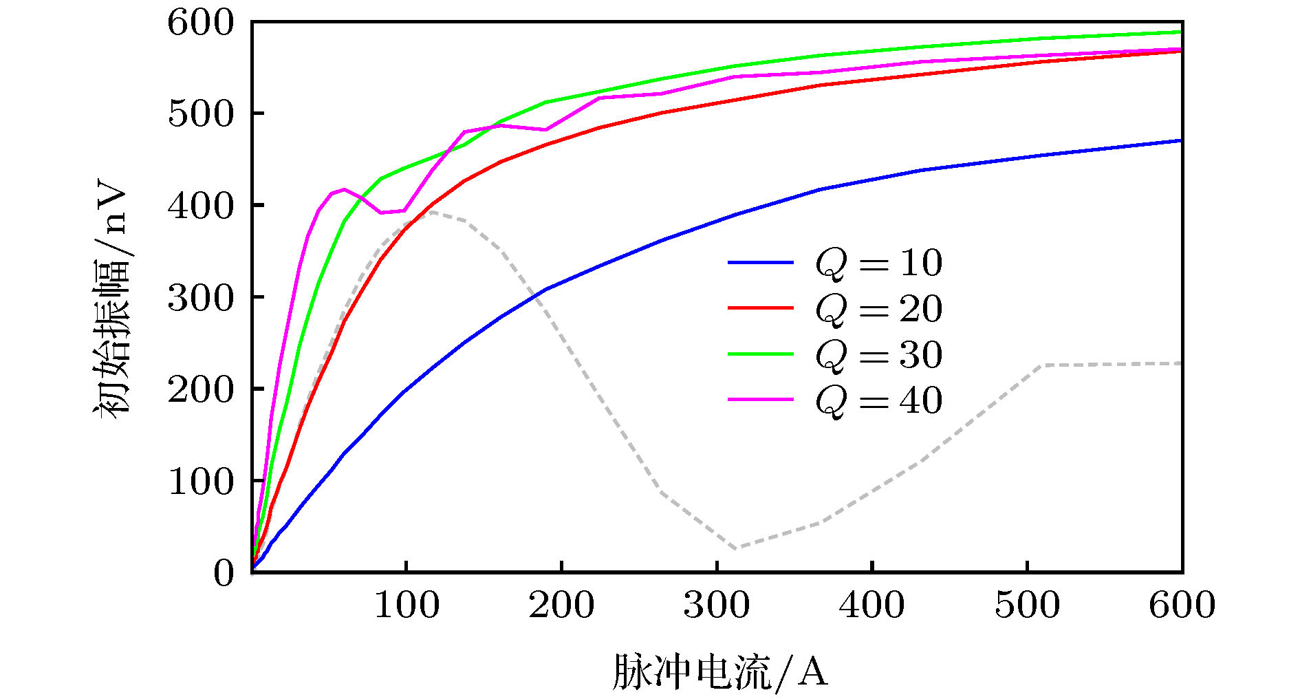 图 10 相同绝热脉冲电流(1—600 A)条件下, 品质因数Q不同时绝热半波对应的正演响应(灰色虚线为传统激发方式信号响应, 假设地下半空间内存在10%均匀的含水量, 发射脉冲持续时间为80 ms)
Figure10. The forward modeling of adiabatic half-passage pulse for the same pulse current (1–600 A) with different quality factor Q (The gray dotted line is the initial amplitude of traditional nuclear magnetic resonance responses). The modeling assume a homogeneous aquifer subsurface with 10% water content with τ = 80 ms.
2
3.4.其他因素
除了发射电流持续时间、电流幅度及线圈品质因数外, 对绝热激发效果影响最大的还是脉冲波形. 根据室内及测井领域总结的经验, 本文应用的双曲正切脉冲及数值优化调制脉冲等均是较为常见的, 能够取得理想信号提升效果的绝热半波. 但由于发射波形复杂, 具体硬件实现也不尽相同, 故较难总结出一定规律, 此处不再多做讨论.1)通过满足绝热条件的扫频变流脉冲, 即绝热脉冲, 可以有效增大氢质子的激发横向磁化强度分量, 从而增强磁共振信号;
2)确定绝热脉冲发射扫频、变流波形后, 其激发横向磁化强度、灵敏度核函数及正演响应, 均可通过求解激发脉冲对应的布洛赫方程实现;
3)除了绝热脉冲类型外, 同一脉冲调制函数下, 脉冲发射电流、持续时间及发射线圈品质因数, 均对信号的提升效果有一定影响;
4)绝热脉冲各个调制参数的确定, 并没有绝对的结论, 需根据具体的探测目标、探测环境及线圈配置等因素, 综合选择各个参数的具体数值, 使信号提升效果最大化. 针对本文应用实验配置, 在激发电流固定情况下, 80 ms脉冲持续时间匹配30品质因数能达到最优信号增强效果.
