


全文HTML
--> --> -->目前, 制备氮化物涂层的主要方法有磁控溅射[16]、多弧离子镀[17]、磁过滤阴极弧等离子体沉积[18]和化学气相沉积[19]等. 物理气相沉积(PVD)制备的大多数薄膜与基体的化学键不匹配且界面处的自由能较高, 导致薄膜内应力较高, 限制了薄膜的生长, 薄膜厚度普遍低于20 μm[20-22]. 化学气相沉积(CVD)制备涂层的速率较低, 且制得的涂层同样存在内应力较高的问题[23,24]. Tushar Banerjee利用脉冲磁控溅射制备了硬度为23 GPa的WSx掺杂TiN涂层, 但涂层的内应力高韧性差, 在摩擦实验中可以观察到硬且脆的WSx掺杂TiN碎片. Ou等结合深振荡磁控溅射和脉冲直流磁控溅射的特点成功制备了硬且韧的CrN/Si3N4复合涂层, 但涂层厚度仅7.4 μm, 限制了涂层的工程应用范围[25].
因此, 合理设计并开发一种制备厚且韧涂层的工艺方法对氮化物涂层的基础研究, 尤其是工程应用具有重大指导意义. 磁过滤阴极弧等离子体沉积是一种基于真空弧技术的薄膜制备方法, 具有电离率高、沉积速率快、靶材易更换等优点[26,27]. 磁过滤弯管能够有效地过滤等离子体中的中性粒子和大颗粒, 使制备的薄膜附着力高, 不易从基底脱落, 避免了薄膜失效[28,29]. 磁过滤阴极弧等离子体沉积最大的特点是通过调控阴极靶的成分、基底温度、真空腔压强、气体流量速率和基底偏压等实现对薄膜生长的控制, 进而提高薄膜的质量. 磁过滤阴极弧是制备厚且韧涂层的潜在方法之一, 但目前有关磁过滤阴极弧等离子体沉积技术制备厚且韧TiN涂层的报道较少, 且缺乏稳定可重复的制备厚度超过20 μm的TiN涂层的工艺方法.
磁过滤阴极弧等离子体沉积技术制备厚且韧TiN涂层的关键在于, 在涂层长厚的过程中, 降低涂层内应力, 阻止柱状晶长大. 在沉积过程中通过高能离子周期性地轰击长大的柱状晶, 打碎大晶粒且降低内应力, 同时控制N2气流量速率不变, 生成稳定的韧性性能较好的非化学计量相TiNx, 从而实现涂层的持续生长和增韧. 基于此, 本文利用磁过滤阴极弧等离子体技术在304 L不锈钢基底上连续沉积了TiN涂层(厚度可达50 μm), 并对厚TiN涂层的力学性能、摩檫学性能进行了表征.
2.1.试样制备
图1为磁过滤阴极弧等离子体沉积设备示意图. 磁过滤阴极弧等离子体设备主要由不锈钢真空室、样品台、缠绕铜线圈的磁过滤弯管、阳极筒和阴极靶组成. 机械泵与分子泵组成的抽真空系统可把不锈钢真空室气压抽至10–3 Pa量级. 样品台可被程序设置绕竖直轴公转和绕水平轴自转. 阴极靶在场致效应作用下离化成等离子体. 图 1 磁过滤阴极弧等离子体沉积设备示意图
Figure1. The schematic diagram of FCVAD system.
选用尺寸为20 mm × 20 mm × 0.5 mm的304L不锈钢作为基片. 不锈钢基片在放入真空室前, 用丙酮浸泡3 min后, 放入无水乙醇中超声清洗5 min. 清洗后的304L不锈钢基片安装在样品台中心位置, 距磁过滤弯管末端150 mm. 阴极靶材选用99.99%纯度的Ti金属靶, 靶直径为100 mm. 利用机械泵与分子泵进行抽真空, 当真空室气压为4 × 10⁻³ Pa时, 对基片表面进行溅射清洗, 分别设置基片偏压为–600, –400和–200 V, 不同偏压下的溅射清洗时间设置为2 min. 溅射清洗结束后, 保持偏压–200 V, 设置弧电流为90 mA, 在基片表面沉积一层纯金属Ti, 作为过渡层, 其厚度不超过总膜厚的10%.
图2为制备超厚TiN涂层的工艺示意图. 基底表面沉积Ti过渡层后, 以15 sccm (1 sccm = 1 ml/min)的流量通入N2, N2分子被Ti等离子体离化, 与Ti等离子体在基片上共同形成TiN涂层. 通入N2后的真空室气压为1.1 × 10⁻² Pa. TiN涂层沉积过程中, 每隔1 h对TiN涂层进行一次高能Ti等离子体轰击处理, 偏压调节为–800 V (Ti等离子体能量为1.6 keV), 轰击时间2 min. 沉积时间分别为125, 150, 190, 210和270 min, 制备得到不同厚度的TiN涂层. 为方便讨论实验结果, 不同沉积时间制备的涂层样品分别命名为TiN-125, TiN-150, TiN-190, TiN-210和TiN-270. TiN-125, TiN-150, TiN-190, TiN-210和TiN-270涂层制备期间高能Ti等离子体轰击次数分别为2, 2, 3, 3, 4.
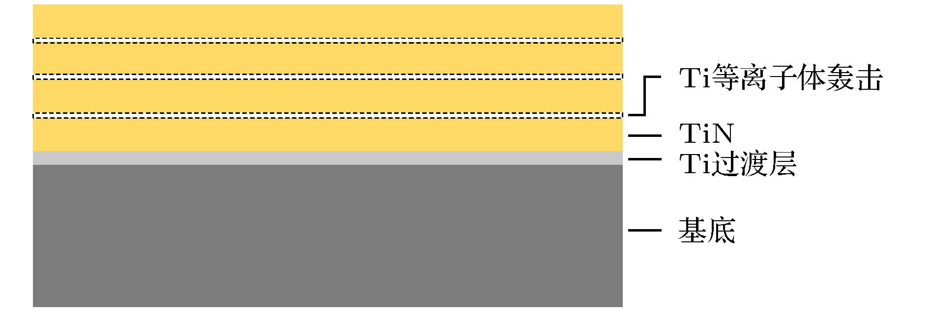 图 2 厚TiN涂层的制备工艺示意图
Figure2. Schematic diagram of preparation process of thick TiNcoating.
2
2.2.表征与分析
采用安东帕公司生产的ToscaTM 400原子力显微镜(AFM)观察涂层的的表面形貌; 采用PANalytica公司生产的X′PertPro MPD型X射线衍射仪(XRD)检测涂层物相结构, X射线激发源为Cu的Kα, 扫描速度设置为2 °/min, 扫描范围设置为30°—90°; 使用XRD半宽峰数据经谢乐公式计算得到晶粒尺寸D = Kλ/(βcosθ), K为常数, 其值与β的定义有关, β为半宽高时, K值为0.89; λ为X射线波长; β为衍射峰半高宽; θ为衍射角; 采用Thermo Fisher公司生产的250Xi型X射线光电子能谱仪(XPS)分析涂层的组成; 采用Hitachi公司生产的S-4800 型扫描电子显微镜(SEM)观察涂层的截面形貌; 采用Talydurf 50轮廓仪测量涂层的厚度, 随机选取5个位置, 取平均值; 采用MML NenoTest P3纳米压痕仪测量涂层的硬度(H)和弹性模量(E), 压痕深度不超过涂层厚度的10%, 随机选取6个点, 取平均值;


3.1.涂层沉积速率
图3为不同沉积时间下的TiN涂层的厚度. 沉积时间为125, 150, 190, 210和270 min的TiN涂层的厚度分别为25, 30, 35, 45和50 μm. TiN-125涂层和TiN-150涂层的沉积速率均为0.2 μm/min. TiN-190涂层、TiN-210和TiN-270涂层的沉积速率分别为0.194, 0.187和0.185 μm/min. TiN涂层的沉积速率随涂层的厚度增加呈减小趋势. 这是因为随着沉积时间的增加, 沉积在基片上的TiN涂层越来越厚, 基片的绝缘性增强, 基片表面正电荷聚集导致到达样品表面的离子能量和数量减少, 使沉积速率降低. 此外, 值得注意的是厚度为TiN-270的涂层的沉积速率最小, 但与TiN-125的涂层的最高沉积速率相比, 仅降低了7.5%, 表明在TiN沉积过程中, 周期性地进行高能离子轰击处理, 对涂层的沉积速率影响较小.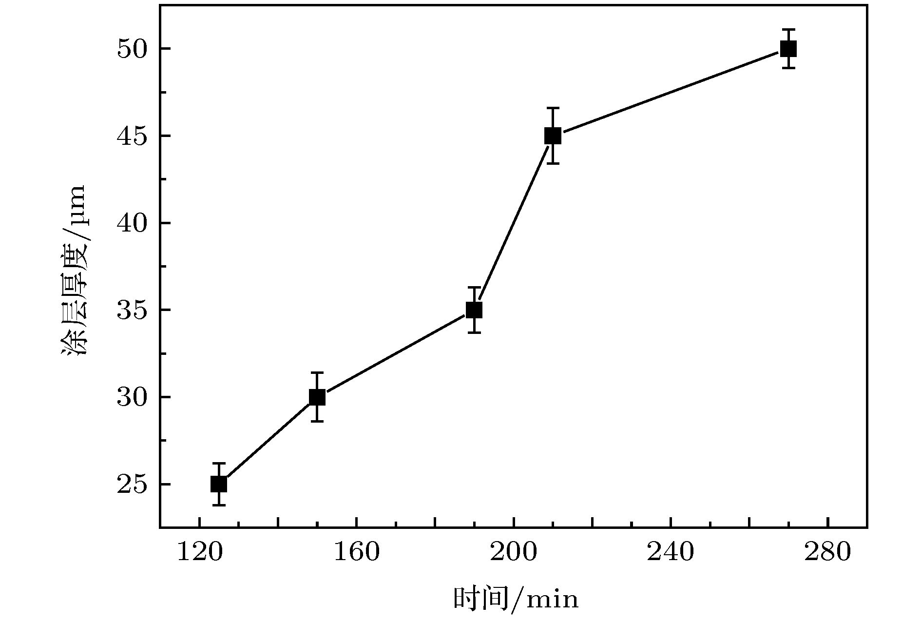 图 3 TiN涂层厚度随沉积时间的变化
Figure3. The evolution of thickness of TiN coatings with deposition time.
2
3.2.形貌结构分析
采用X Pert PRO MPD衍射仪对涂层做XRD扫描分析. 图4为所有TiN涂层的XRD图谱及不同沉积时间下样品的晶粒尺寸. 晶粒尺寸根据谢勒公式计算得到, 半峰宽通过对(111)峰进行高斯拟合后获得. 所有的涂层表现出典型的面心立方结构, 涂层由TiN相和非化学计量TiN0.9相组成, 涂层的应变能较低导致TiN相沿(111)密排面择优取向生长[30]. 非化学计量比TiNx (x < 1)与TiN相比, 应变能小、韧性高且抗冲蚀性能优良[31,32], TiN0.9相的存在使制备的TiN硬质涂层具有一定的韧性. 随着沉积时间的增加, (111)衍射峰的强度逐渐升高, 半峰宽数值呈递减变化, 涂层的晶粒从16.57 nm逐渐增大到27.66 nm, 这与Hu等[33]报道的一致, 涂层厚度增加, 晶粒粗化效应明显, 涂层越厚, 表面晶粒尺寸越大. 此外, 可以观察到样品的TiN(111)峰位向高衍射角偏移, 这与涂层的残余应力随涂层增厚而逐渐减小有关.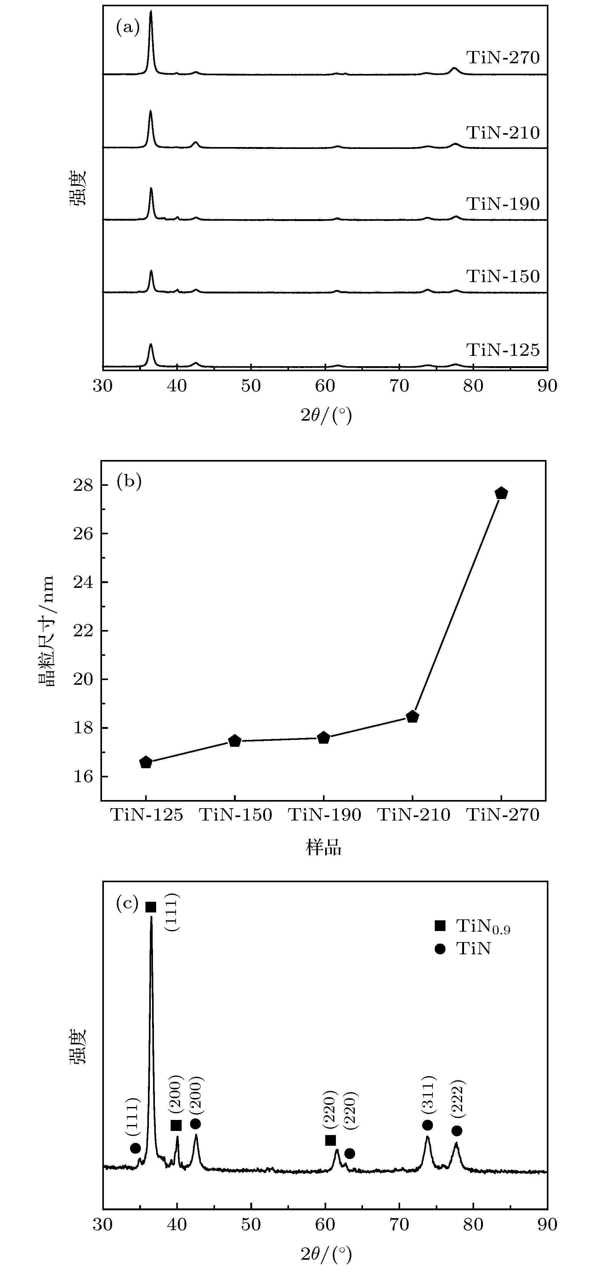 图 4 (a) 不同沉积时间的TiN涂层的XRD谱图; (b) 不同沉积时间的TiN涂层的晶粒尺寸; (c) TiN-125涂层的XRD谱图
Figure4. (a) XRD patterns of all of the TiN coatings with different deposition time; (b) the grain size of all of the TiN coatings with different deposition time; (c) XRD patterns of TiN-125 coating.
由XRD结果可知, 在制备TiN-125, TiN-150, TiN-190, TiN-210和TiN-270涂层过程中, 高能离子轰击对涂层的物相组成及结构影响较小, 各涂层的物相组成基本相同, 选择TiN-125涂层进行XPS分析. TiN-125涂层的XPS图谱如图5所示, N 1s谱峰的结合能在395—400 eV之间, 经泰勒解谱后分别在396.9和398.67 eV附近出现两个分峰, 位于396.9 eV处的N峰对应TiN中的N原子[34], 398.67 eV处的N峰对应TiN0.9中的N原子[35], Ti和N等离子体形成TiN的同时, 也生成了韧性较好的TiN0.9, 这与XRD分析的结果一致. 磁过滤阴极弧制备的厚TiN涂层由于存在非化学计量TiN0.9, 使TiN涂层具有高硬度的同时提高了涂层韧性.
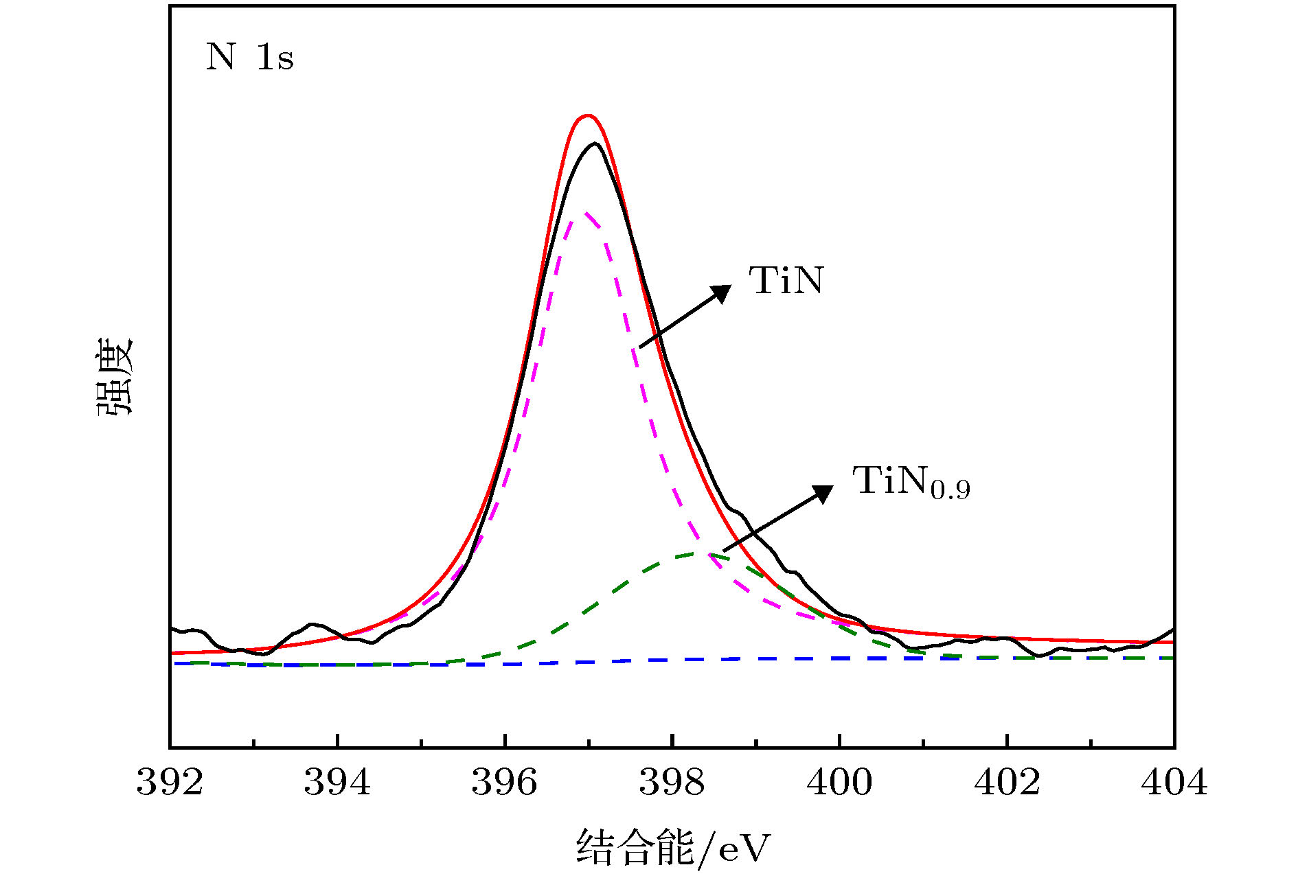 图 5 TiN-125涂层N 1s的XPS谱图
Figure5. XPS spectta of N 1s of TiN-125 coating.
用原子力显微镜观察涂层的表面形貌. 不同沉积时间的TiN涂层的表面形貌及粗糙度如图6所示, 测试的区域为1 μm × 1 μm. TiN-210和TiN-270涂层的粗糙度相同, 为10.5 nm. TiN-125, TiN-150和TiN-190涂层粗糙度均小于10 nm, 分别为6.37, 6.68和9.64 nm. 涂层的沉积时间越长, 粗糙度越大. 沉积时间超过150 min后, 涂层的沉积速率略微降低, 涂层表面的颗粒团聚现象增多, 大颗粒越来越多. 随着TiN涂层厚度增加, 涂层表面的晶粒粗化效应明显, 大尺寸晶粒增多, 且更易成为涂层生长核心, 沿柱状晶方向持续长大形成大颗粒, 增大涂层表面粗糙度. 对于厚度超过35 μm的厚涂层, 高能离子轰击打碎大晶粒的作用减弱, 造成TiN-210和TiN-270涂层的粗糙度趋于相同.
 图 6 不同沉积时间下的TiN涂层的AFM图及表面粗糙度 (a) 125 min; (b) 150 min; (c) 190 min; (d) 210 min; (e) 270 min; (f) 不同TiN涂层的表面粗糙度
Figure6. The AFM and roughness of all of the TiN coatings with different deposition time: (a) 125 min; (b) 150 min; (c) 190 min; (d) 210 min; (e) 270 min; (f) roughness of all of the TiN coatings.
TiN涂层的截面SEM扫描图如图7所示. 在基底与TiN涂层之间存在Ti过渡层, 其厚度分别为5 μm (TiN-125), 12 μm (TiN-150), 12 μm (TiN-190), 10 μm (TiN-210)和11 μm (TiN-270). 除TiN-190涂层外, TiN-125, TiN-150, TiN-210和TiN-270涂层的Ti过渡层与基底有明显的分界, 表明TiN-190涂层的结合力可能高于其他涂层. 此外, 可以观察到所有的TiN涂层的微结构是致密连续的, 表明制备的超厚TiN涂层的硬度较大, 且能承载较高的载荷.
 图 7 不同沉积时间下TiN涂层的SEM截面形貌 (a) 125 min; (b) 150 min; (c) 190 min; (d) 210 min; (e) 270 min;
Figure7. Cross-sectional SEM micrographsof TiN coatings with different deposition time: (a) 125 min; (b) 150 min; (c) 190 min; (d) 210 min; (e) 270 min.
2
3.3.涂层力学性能分析
TiN涂层的硬度H和弹性模量E如图8所示. TiN涂层的微结构连续致密, 表现出高硬度力学性能. 制备的厚TiN样品的硬度均超过26 GPa, 属于超硬涂层. TiN-125涂层的硬度和弹性模量最高, 分别达到38.24 和386.53 GPa. 随着沉积时间的增加, TiN涂层不断长大, 涂层的硬度和弹性模量均表现出下降的趋势, 涂层越厚, 硬度越低, 弹性模量越小. TiN涂层的硬度和弹性模量分别从38.24 和386.53 GPa先缓慢地下降到35.74 和370.20 GPa附近后又快速地下降到27.63 和316.37 GPa. 由图4(b)可知, TiN涂层在长大的过程中晶粒尺寸逐渐长大并粗化, 导致了涂层的硬度和弹性模量降低. 这与文献报道的一致, 晶粒粗化与涂层生长时间遵循经典的Hall-Petch关系[33,36].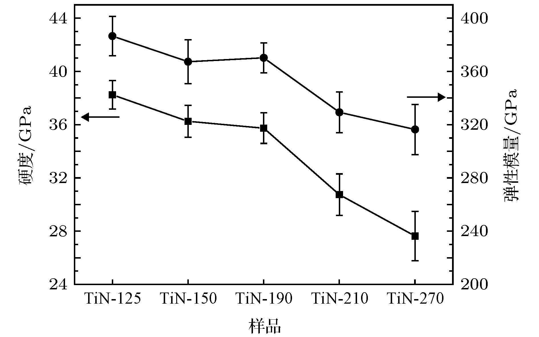 图 8 不同沉积时间下TiN涂层的硬度和弹性模量
Figure8. Hardness and elastic modulus of TiN coatings with different depositiontime.
近些年来,


 图 9 不同沉积时间下TiN涂层的

Figure9.


洛氏压痕常被用来定性地评估涂层的结合力, 图10为厚TiN涂层的洛氏压痕形貌. 所有TiN涂层的中心位置处都发生了严重的变形, 且在压痕边缘处有环形裂纹, 但TiN-210和TiN-270涂层的裂纹明显多于TiN-125, TiN-150和TiN-190涂层. TiN-210和TiN-270涂层由于晶粒粗化, 表面的大颗粒增多、粗糙度变大, 降低硬度的同时, 也降低了涂层的承载性能, 相同载荷下, 产生的裂纹数增多. TiN-125涂层的压痕上的裂纹数目少、长度短且压痕形变最小, 表明TiN-125涂层的结合力高于其他涂层, 且涂层的抗裂纹形成和扩展性能优良. TiN-210和TiN-270涂层的压痕图上的裂纹较多, 且能观察到微碎片和分层, 这与前述TiN涂层


 图 10 不同TiN涂层的洛氏压痕形貌 (a) TiN-125; (b) TiN-150; (c) TiN-190; (d) TiN-210; (e) TiN-270
Figure10. SEM images of HRC indents of different TiN coatings. (a) TiN-125; (b) TiN-150; (c) TiN-190; (d) TiN-210; (e) TiN-270
不同沉积时间的厚TiN涂层的平均内应力由Stony公式计算:


不同沉积时间下TiN涂层的内应力变化如图11所示. 应力从TiN-125的0.811 GPa快速下降到TiN-150的0.643 GPa后基本保持稳定. 当沉降时间超过210 min后, 平均内应力从0.583 GPa迅速下降到TiN-270的0.43 GPa, TiN涂层的平均内应力随着沉积时间的增加整体上表现出下降的趋势. 影响平均内应力的主要因素有两个, 分别是涂层与基底之间不同的热膨胀系数和热应力. 若304不锈钢基底和TiN涂层直接接触, 在降温过程中基底和TiN涂层的收缩趋势不一致, 易导致TiN涂层产生较大的应变, 使涂层崩落无法继续长厚. 本实验中, 在不锈钢基底和TiN涂层之间沉积的Ti过渡层作为缓冲层, 能够有效减小涂层与基底的收缩趋势, 从而降低应力. 随着沉积时间的增加, TiN涂层越来越厚, 热应力得以均匀分布, 很难到达涂层与基底间的接触面, 使涂层避免因热应力而失效. 此外, 与薄膜相比, 厚涂层在沉积过程中有更长的时间释放热应力, 进一步降低热应力对涂层的影响.
 图 11 不同沉积时间下TiN涂层的内应力变化
Figure11. Theevolutionofinternalstress of TiN coatings with different deposition time.
采用往复磨擦试验测试超厚TiN涂层的摩擦学性能. 摩擦介质为空气, 实验温度为25 ℃. 图12(a)为TiN涂层的摩擦系数随测试时间的变化关系. TiN-125, TiN-150, TiN-190, TiN-210和TiN-270涂层的平均摩擦系数是0.26, 0.34, 0.38, 0.45和0.55. 由图6、图8和图9


 图 12 (a) TiN涂层的摩擦系数随测试时间的变化; (b) 不同沉积时间下TiN涂层的磨损速率
Figure12. (a) The evolution of coefficient of friction of TiN coatings with testing time; (b) wear rate of TiN coatings with different deposition time.
 图 13 不同TiN涂层的表面磨损形貌
Figure13. SurfacewearmorphologyofdifferentTiNcoatings.
