Fund Project:Project supported by the National Natural Science Foundation of China (Grant Nos. 51175479, U1704155), the Key Scientific Research Projects of the Higher Education Institutions of Henan Province, China (Grant Nos. 16A140035, 18A140032), and the Science and Technology Innovation Team in Colleges and Universities of Henan Province, China (Grant No. 18IRTSTHN016).
Received Date:17 December 2018
Accepted Date:19 February 2019
Available Online:01 May 2019
Published Online:20 May 2019
Abstract:Incoherent digital holography (IDH) is a recently proposed technique to record three-dimensional (3D) information about the object under incoherent illumination, which breaks the limitation that the holographic recording must be illuminated by coherent light sources and thus makes it usable in white-light and fluorescence illuminating circumstance. In particular, the fresnel incoherent correlation holography (FINCH) is an exemplary method which improves the imaging resolution power and efficiency of incoherent digital holography, and it can obtain 3D distribution of objects swiftly without scanning and moving. However, compared with the conventional optical holography, the FINCH system has a very small field-of-view due to the limitation of the pixel number and size of spatial light modulator (SLM). Therefore, expanding the recording field-of-view of FINCH system is very significant for the application of IDH. In the FINCH, the SLM is used as a diffractive beam splitter so that each spherical beam, originating from each object point, is split into two spherical beams with two different curve radii. Then the interference fringes between the two beams are recorded by CCD. In this paper, the field-of-view angle recorded by the SLM is proposed and analyzed based on the physical and numerical principles of the FINCH system. The field-of-view of imaging system is improved by increasing the effective diameter of SLM through moving the center of the dual-lens optical axis mounted on the SLM to the edge in different directions respectively. An optical setup of reflection mode is constructed to verify the theoretical analysis of this study, and the sub-holograms in different field-of-views are obtained by CCD through changing the masks displayed on the SLM sequentially. Then, the complex holograms in different field-of-views are obtained by using the three-step phase-shifting method, and the reconstructed images are acquired respectively through the angular spectrum method (ASM) by using a computer. Finally, the large field-of-view image is obtained by stitching the reconstructed images in each field-of-view by utilizing the matlab program. The experimental results show that the efficient recording field-of-view of SLM can be increased by 2.77 times with our proposed method. Accordingly, the recording field-of-view of the system is improved significantly. The recording field-of-view of the FINCH system will increase further if the center of the dual-lens optical axis continues to move toward the edge. Therefore, this study provides an important support for the further application of high resolution microscopic imaging with large field-of-view. Keywords:incoherent digital holography/ spatial light modulator/ imaging field-of-view/ field-of-view splicing
图 2 FINCH大视场成像原理图 (a) SLM记录视场角; (b)四次记录光轴中心位置; (c)九次记录光轴中心位置; (d)光轴中心处于图(b)中O点时的掩模; (e)光轴中心处于图(b)中B点时的掩模; (f)光轴中心处于图(c)中C点时的掩模 Figure2. Schematic diagrams of FINCH with large field-of-view imaging: (a) The recording field-of-view angle of SLM; (b) the central position of the optical axis for recording four times; (c) central position of optical axis for recording nine times; (d) optical axis center is at point O of (b); (e) optical axis center is at point B of (b); (f) optical axis center is at point C of (c).
在整个记录过程, 将SLM上加载的双透镜掩模按照图2(b)所示方式依次更换光轴中心的位置(掩模如图3所示), 分别进行FINCH记录, 并将各视场的子图像拼接融合获得大视场图像. 结合(2)式和(3)式, 可以计算出SLM的有效记录范围增大至原来的2.25倍. 如果按照图2(c)所示方式改变掩模双透镜光轴中心的位置(如图2(f)所示), 当图2(d)中的c点移至图2(f)中的c”点时, 同理可以计算出SLM的有效记录范围增大至最初的2.77倍. 假若将SLM幅面划分得更多, 双透镜光轴中心将继续向边缘移动, 最大会移动至SLM的最边缘, 此时SLM的有效记录面积达到最大, 为原来的4倍. 但划分的区域越多, FINCH记录的次数越多, 成像速度会大大降低. 图 3 双透镜光轴中心处于四个不同位置的掩模 Figure3. The masks with the center of dual-lens optical axis in four different positions
3.实验系统本实验搭建的是如图4所示的非相干光反射式数字全息记录系统, 采用连续的白光光谱光源(CLE-TCX250,250W), 会聚透镜L1焦距为60 mm, 滤光片(BF)的带宽为20 nm, 中心波长为632.8 nm, BS1, BS2为分束器, USAF 1951 分辨率板为待测样品, Polarizer为偏振片, 其偏振方向与SLM的液晶长轴方向一致, 准直透镜L2的焦距为250 mm, SLM像素数为1920 × 1080, 像素尺寸为8 μm, CCD像素大小为4.54 μm, 像素数为2750 × 2200, 拍摄时实际所用像素数为2048 × 2048. 待测物体与L2之间的距离为250 mm, L2与SLM之间的距离为140 mm, SLM到BS2与BS2到CCD的距离之和为250 mm. 图 4 非相干光反射式数字全息实验光路 Figure4. Experimental set-up of incoherent light reflection digital holography
实验记录过程中只需通过计算机给SLM依次更换不同光轴中心的相位掩模, 记录各视场的相移全息图. 4.实验结果与分析采用图4所示非相干光反射式数字全息记录系统进行实验探究, 分别在SLM上依次加载图3中的掩模, CCD记录下USAF 1951 分辨率板不同视场的全息图, 利用角谱衍射法将全息图重建, 得到如图5(a)—图5(d)所示的子图像. 利用Matlab软件将各子图像拼接处理得到如图5(f)所示的大视场图像, 图5(e)为常规FINCH记录得到的再现像, 可以看出, 图5(f)的视场范围明显大于图5(e), 所以采用本研究方法可以增大系统的记录视场. 为了能够进一步说明增大成像视场的同时没有影响分辨率, 绘制了图5(b)和图5(e)红线处的强度分布曲线图, 分别为图5(g)和图5(h), 观察图5(g)和图5(h)可知, 当加载设计的大视场掩模时所获得的重建像质量较高, 噪声没有增加, 并且峰值没有下降, 红色曲线分布也比较均匀, 更加有力地说明了本实验方法可以同时实现高分辨率大视场成像. 图 5 USAF1951分辨率板重建像 (a)?(d)分别为加载图3中掩模所得; (e)常规再现像; (f)大视场图像; (g)为(b)红线处的强度分布曲线图; (h)为(e)红线处的强度分布曲线 Figure5. Reconstruction images of USAF1951 resolution plate: (a)?(d) are mounted with Fig. 3 (d) masks, respectively; (e) normal reconstruction images; (f) large field-of-view images; (g) the intensity distribution at the position of the red line of (b); (h) the intensity distribution at the position of the red line of (e)
另外, 我们对本文所提出的菲涅耳非相干数字全息大视场方法进行了更深一步的实验研究, 以R1L3S5P分辨率板作为记录物体, 结果如图6所示. 实验中, 首先在SLM上加载如图6(a)所示掩模记录物体的全息图, 经过三步相移线性处理后采用角谱法再现, 获得的重建像如图6(b)所示; 其次在SLM上依次更换如图6(c)中不同光轴中心的掩模, 将记录的四幅子图像进行再现、拼接处理后得到如图6(d)所示的大视场图像; 最后以相同的方法给SLM依次加载如图6(e)中的各个掩模, 最后得到九个不同视场下的重建像, 经过拼接处理后得到如图6(f)所示大视场图像. 比较图6(b)和图6(d)可以发现前者在视场边缘周围没有记录到的信息在后者中被记录下来, 后者的视场信息完全包含了前者, 大大扩增了前者四周的视场; 观察图6(d)和图6(f)可以看到图6(f)所记录的视场范围相对于图6(d)中的视场有了进一步增大. 实验结果表明当将加载在SLM上掩模的光轴中心向边缘移动时可以有效扩大系统的记录视场, 充分证实了本研究方法通过增大SLM的有效直径实现了FINCH系统的大视场高分辨成像. 当然, 随着SLM上光轴记录中心的增多, 成像速度会降低, 对于四个光轴中心利用三步相移技术只需要拍摄12次, 如果是九个光轴中心将要拍摄27次, 如果将光轴中心进一步向边缘移动, 则记录时间会大大增加. 图 6 R1L3S5P分辨率板重建像 (a)常规掩模; (b)常规再现像; (c)四次记录掩模; (d)由四个子图像拼接得到的大视场图像; (e)九次记录掩模; (f)由九个子图像拼接得到的大视场图像 Figure6. Reconstruction images of R1L3S5P resolution plate: (a) Conventional mask; (b) conventional reconstruction image; (c) masks of four records; (d) large field-of-view images obtained by splicing four sub-images; (e) masks of nine records; (f) large field-of-view images obtained from nine sub-images
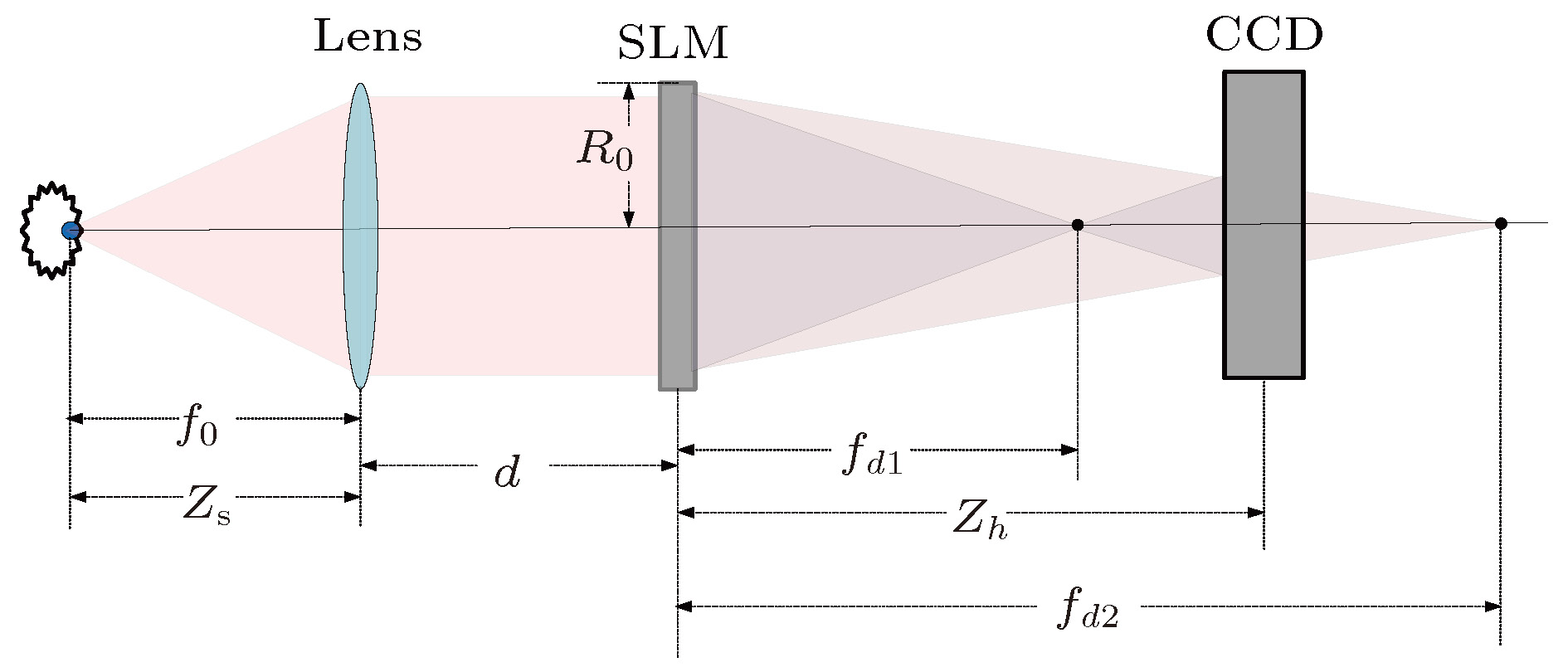 图 1 FINCH系统成像原理图
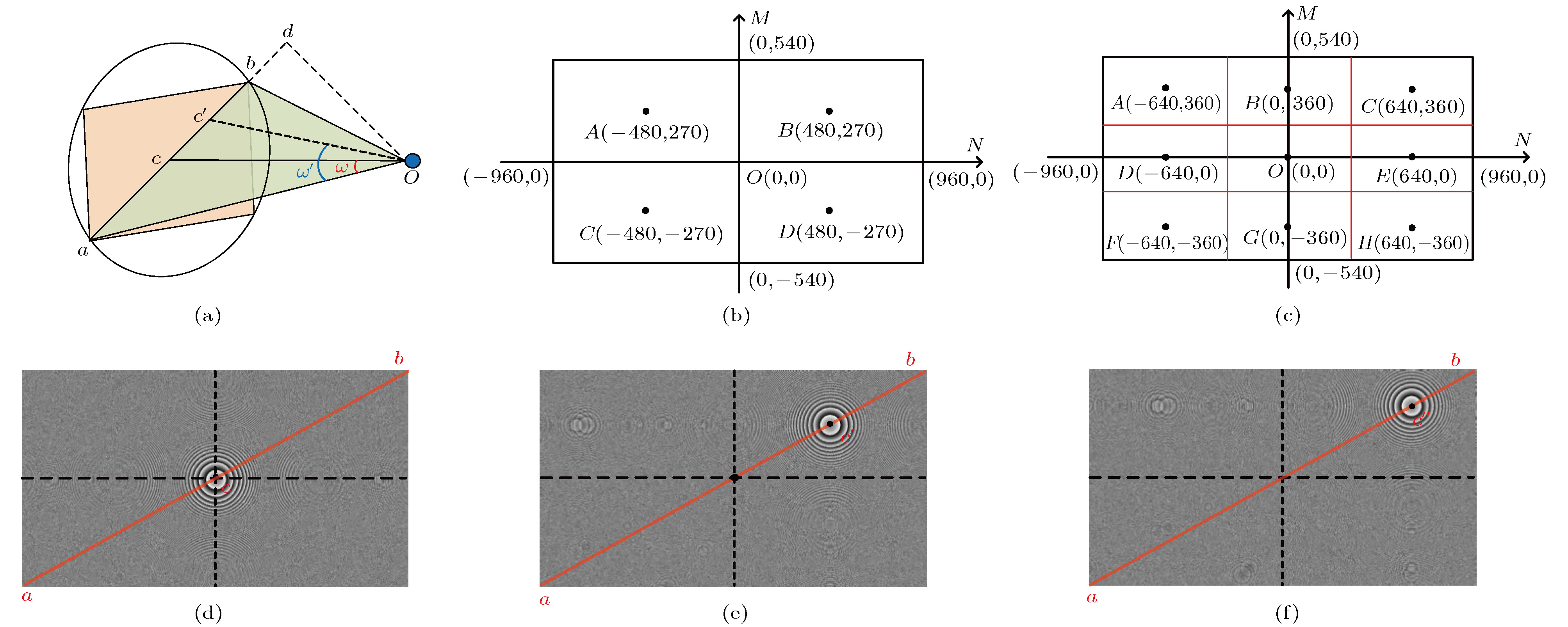 图 2 FINCH大视场成像原理图 (a) SLM记录视场角; (b)四次记录光轴中心位置; (c)九次记录光轴中心位置; (d)光轴中心处于图(b)中O点时的掩模; (e)光轴中心处于图(b)中B点时的掩模; (f)光轴中心处于图(c)中C点时的掩模


 图 3 双透镜光轴中心处于四个不同位置的掩模
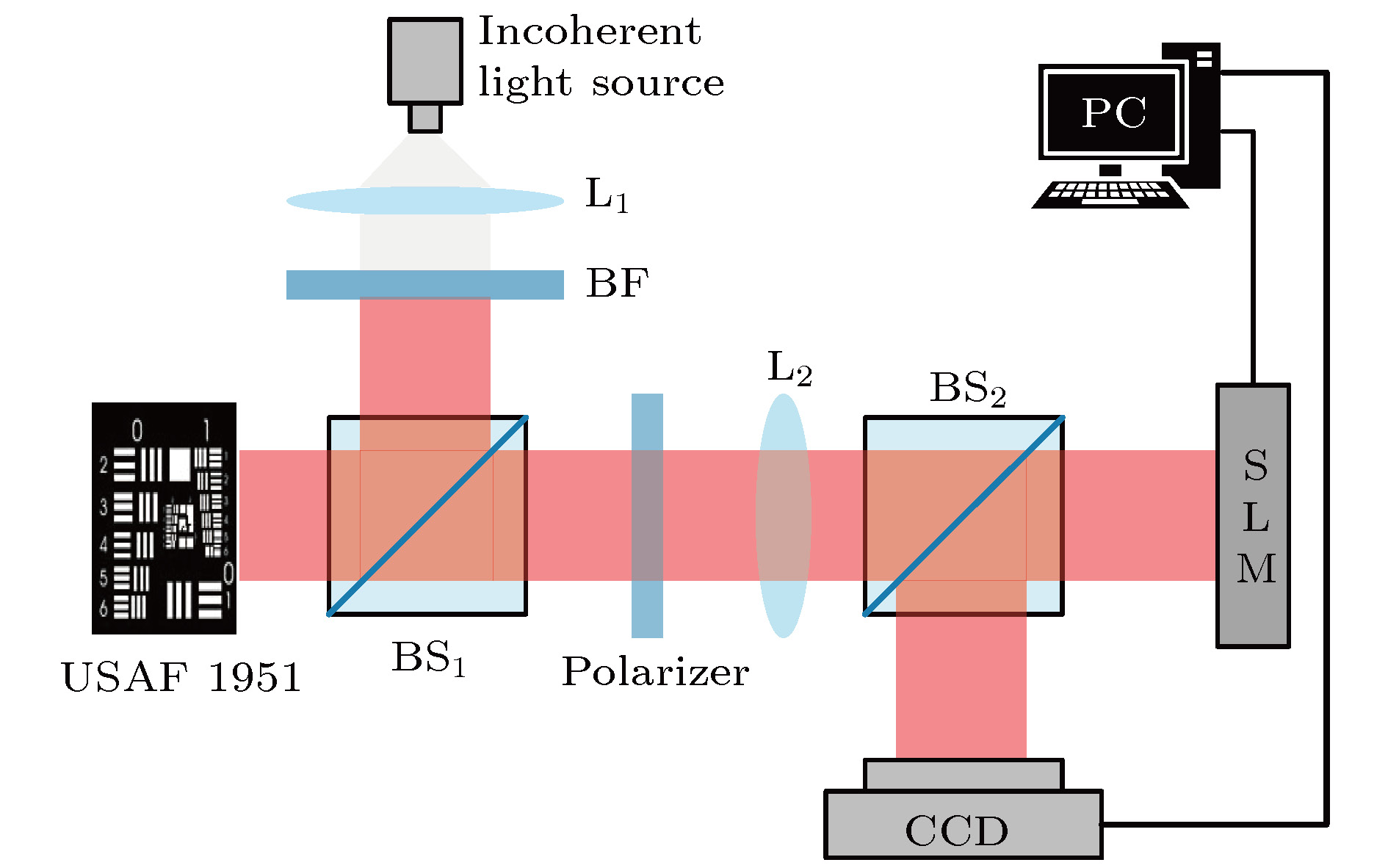 图 4 非相干光反射式数字全息实验光路
 图 5 USAF1951分辨率板重建像 (a)?(d)分别为加载图3中掩模所得; (e)常规再现像; (f)大视场图像; (g)为(b)红线处的强度分布曲线图; (h)为(e)红线处的强度分布曲线
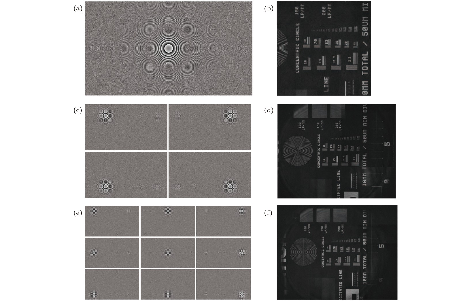 图 6 R1L3S5P分辨率板重建像 (a)常规掩模; (b)常规再现像; (c)四次记录掩模; (d)由四个子图像拼接得到的大视场图像; (e)九次记录掩模; (f)由九个子图像拼接得到的大视场图像