1.College of Physics and Electronic Engineering, Shanxi University, Taiyuan 030006, China 2.State Key Laboratory of Quantum Optics and Quantum Optics Devices, Institute of Laser Spectroscopy, Shanxi University, Taiyuan 030006, China 3.Collaborative Innovation Center of Extreme Optics, Shanxi University, Taiyuan 030006, China
Fund Project:Project supported by the National Natural Science Foundation of China (Grant Nos. 61378039, 61575115) and the National Science Fund for Talent Training in Basic Science of the National Natural Science Foundation of China (Grant No. J1103210).
Received Date:26 November 2018
Accepted Date:27 December 2018
Available Online:01 March 2019
Published Online:05 March 2019
Abstract:In this paper, an elliptical dielectric graphene-coated nanowire optical waveguide is designed. In the elliptical cylinder coordinate system, the dispersion equation is obtained by using the separation variable method with the Mathieu functions. The effective refractive indexes and the field distributions are obtained from the dispersion equation by using the numerical method, then the propagation lengths are obtained. The influence of the operating wavelength, structure parameters and the Fermi energy of graphene on the mode characteristics are investigated. What is more, the figure of merit of the first five modes are calculated too. The influence of the operating wavelength and the graphene Fermi energy on the mode characteristics of circular nanowires and that of elliptical nanowires are compared. The results show that as the operating wavelength increases from 4.3 ${\text{μ}}{\rm{m}}$ to 8.8 ${\text{μ}}{\rm{m}}$, the real part of the effective refractive index decreases monotonically, the propagation lengths of the fundamental mode and the 1st order modes increase, and the 2nd order modes first increase and then decrease. When changing the elliptical nanowire structure parameters—the length of semi-major axis and semi-minor axis, there are slight influence on the mode characteristics of the fundamental mode and the 1st order modes, but greater influence on those of the 2nd order modes. As the Fermi energy of graphene increases from 0.45 eV to 0.72 eV, in the first five modes, the real part of the effective refractive index decreases, the propagation lengths of the fundamental mode and the 1st order modes increase, the propagation lengths of the 2nd order modes decrease. In addition, the propagation length approaches to 2 ${\text{μ}}{\rm{m}}$ approximately. When the semi-minor axis b = 100 nm and ?${E_{\rm F}} \;{\rm{ = 0}}{\rm{.5}}\;{\rm{eV}}$, the curves of the circular nanowire (a = 100 nm) and the elliptical nanowire (a = 140 nm), the real part of the effective refractive index and propagation length with the operating wavelength and the Fermi energy of graphene are compared. Then, the advantages of elliptical nanowire over the circular nanowire are verified. The results of the separation variable method are in good agreement with the results of the finite element method. This work can provide a theoretical basis for the design, fabrication and application of optical waveguides based on graphene-coated elliptical dielectric nanowires. Keywords:graphene/ nanowires/ waveguides/ separation variable method
3.结果及分析图2(a)—图2(e)分别给出在a = 110 nm, b = 80 nm, ${E_{\rm{F}}} = 0.{\rm{5\; eV}}$和$\lambda\; {\rm{ = 7}}\;{\text{μ}}{\rm{m}}$的情况下, 该波导支持的五个最低阶模式(依次命名为Mode 1, Mode 2, Mode 3, ${\rm{Mode 4}}$和Mode 5)对应的z方向电场分量${E_z}$分布, 图2(f)—图2(j)为其对应的电场强度$\left| E \right|$分布. 可以看出, 场集中分布在石墨稀涂层附近. 其中Mode 1为基模, Mode 2和Mode 3为一阶模, Mode 4和Mode 5为二阶模. Mode 1, Mode 3和Mode 5为偶模, Mode 2和Mode 4为奇模. 图 2 在a = 110 nm, b = 80 nm, ${E_{\rm{F}}}= 0{\rm{.5\; eV}}$和$\lambda = 7\;{\text{μ}}{\rm{m}}$的情况下, 前五个模式对应的z方向电场分量${E_z}$(a)—(e)与电场强度$\left| E \right|$分布图(f)—(j) Figure2. The z direction electric field component ${E_z}$ (a)—(e)and electric field intensity $\left| E \right|$(f)—(j) corresponding to the first 5 modes with a = 110 nm, b = 80 nm, ${E_{\rm{F}}} = 0{\rm{.5\; eV}}$ and $\lambda = 7\;{\text{μ}}{\rm{m}}$.
图3(a)—图3(c)分别给出了在a = 110 nm, b = 80 nm和${E_{\rm{F}}} {\rm{ = 0}}{\rm{.5 eV}}$的情况下, 有效折射率实部${\rm{Re}} \left( {{n_{{\rm{eff}}}}} \right)$、传播长度${L_{{\rm{prop}}}}$和品质因数FOM与波长$\lambda $之间的依赖关系. 图中实线为 FEM 的模拟结果, 点线为分离变量法得到的计算结果, 下文中均用该方法标注. 从图3中可以看出, 随着波长的增大, 前五个模式的有效折射率的实部都单调减小, 其中Mode 1, Mode 2和Mode 3 的有效折射率的实部下降较慢, 而Mode 4和Mode 5的有效折射率的实部下降较快. 随着波长的增大, Mode 1, Mode 2与Mode 3的传播长度单调增加, 而Mode 4和Mode 5的传播长度先增大后减小. 随着波长的增大, 品质因数FOM先增大再逐渐减小, 其中Mode 1, Mode 2和Mode 3的品质因数下降较慢, 而Mode 4和Mode 5的品质因数下降较快. 因为品质因数FOM越大, 波导的传输性能越好[35], 在所选参数范围内, Mode 2的品质因数最大, 所以Mode 2的传输性能最好. 图 3 在a = 110 nm, b = 80 nm和${E_{\rm{F}}} = 0{\rm{.5\; eV}}$的情况下, 有效折射率实部(a), 传播长度(b)和品质因数(c)与波长的关系 Figure3. Dependence of the real part of the effective refractive index (a), propagation length (b) and FOM (c) on the wavelength with a = 110 nm, b = 80 nm and${E_{\rm{F}}} = 0{\rm{.5\; eV}}$.
上述现象可以通过场分布来解释. 以Mode 5为例, 图4给出了$\lambda\; {\rm{ = 5}}{\rm{.0 }}$, 7.5和8.5 ${\text{μ}}{\rm{m}}$三种情况下电场强度分布的对比图. 从图中可以看出, 当$\lambda\; {\rm{ = 5}}{\rm{.0}}\;{\text{μ}}{\rm{m}}$时, 场被紧密地约束在石墨烯涂层附近, 场与石墨烯涂层之间的相互作用强, 此时波导对场的约束性非常强, 能量分布集中, 但模式的传输损耗较大, 传播长度较小. 当$\lambda\; {\rm{ = 7}}{\rm{.5}}\;{\text{μ}}{\rm{m}}$时, 场分布扩散至电介质纳米线和空气中, 场与石墨烯涂层之间的相互作用变弱, 波导对场的束缚性变弱, 传输损耗减小, 因而传播长度增大. 当$\lambda\; {\rm{ = 8}}{\rm{.5}}\;{\text{μ}}{\rm{m}}$时, 虽然场分布扩散到电介质纳米线和空气中的越来越多, 波导对场的束缚性变弱, 但是石墨烯涂层附近的场的强度增强, 场与石墨烯之间的相互作用变强, 传输损耗增大, 因而传播长度减小. 图 4 在a = 110 nm, b = 80 nm和${E_{\rm{F}}} = 0{\rm{.5 \;eV}}$的情况下, 不同波长时Mode 5的电场强度$\left| E \right|$分布图 (a)$\lambda = 5{\rm{.0}}\;{\text{μ}}{\rm{m}}$; (b)$\lambda = {\rm{7}}{\rm{.5}}\;{\text{μ}}{\rm{m}}$; (c)$\lambda = {\rm{8}}{\rm{.5}}\;{\text{μ}}{\rm{m}}$ Figure4. The distribution of the electric field intensity $\left| E \right|$ of the Mode 5 with different wavelength when a = 110 nm, b = 80 nm and ${E_{\rm{F}}} = 0{\rm{.5 \;eV}}$: (a)$\lambda = 5{\rm{.0}}\;{\text{μ}}{\rm{m}}$; (b)$\lambda = {\rm{7}}{\rm{.5}}\;{\text{μ}}{\rm{m}}$; (c)$\lambda = {\rm{8}}{\rm{.5}}\;{\text{μ}}{\rm{m}}$.
图5(a)—图5(c)分别给出了在b = 90 nm,${E_{\rm{F}}}\;{\rm{ = 0}}{\rm{.5 \;eV}}$和$\lambda\; {\rm{ = 7}}\;{\text{μ}}{\rm{m}}$的情况下, 有效折射率实部${\rm{Re}} \left( {{n_{{\rm{eff}}}}} \right)$、传播长度${L_{{\rm{prop}}}}$和品质因数FOM与半长轴a的关系. 从图中可以看出, 当半短轴b的长度一定时, 随着a的增大, 前5个模式的有效折射率的实部逐渐增大, 其中Mode 3的有效折射率的实部变化极小, Mode 1和 Mode 2的有效折射率的实部增长速度比Mode 4和Mode 5的慢. 随着a的增大, Mode 1的传播长度基本不变, Mode 3的传播长度缓慢减小, Mode 2, Mode 4和Mode 5的传播长度缓慢增大. 随半长轴a的增大, Mode 1和Mode 2的品质因数增加较慢, Mode 3的品质因数缓慢减小, Mode 4和Mode 5的品质因数增加较快. 在所选参数范围内, Mode 2的品质因数最大, 传输性能最好. 图 5b = 90 nm, ${E_{\rm{F}}} = 0{\rm{.5 \;eV}}$和$\lambda = 7\;{\text{μ}}{\rm{m}}$的情况下, 有效折射率实部(a), 传播长度(b)和品质因数(c)与半长轴a的关系 Figure5. The real part of the effective refractive index (a), propagation length (b) and FOM (c) as a function of semi-major axis when b = 90 nm, ${E_{\rm{F}}}= 0{\rm{.5 \;eV}}$and $\lambda = 7\;{\text{μ}}{\rm{m}}$.
上述现象可以通过场分布来解释. 以Mode 5为例, 图6给出了当b = 80 nm, ${E_{\rm{F}}}\;{\rm{ = 0}}{\rm{.5 \;eV}}$, $\lambda \;{\rm{ = 7}}\;{\text{μ}}{\rm{m}}$时, a = 100, 120和140 nm情况下的电场强度$\left| E \right|$分布对比图. 从图中可以看出, 当a = 100 nm时, 石墨烯椭圆环的周长较小, 场被约束在石墨烯椭圆环附近, 场与石墨烯之间的相互作用强, 模式的传输损耗大, 传播长度小. 当a = 120 nm时, 石墨烯椭圆环的周长变大, 场分布的范围扩大, 在半长轴增大的过程中, 左右花瓣对应的场的强度基本保持不变, 而上下花瓣对应的场的强度减小, 场与石墨烯之间的相互作用变弱, 传输损耗减小, 因而传播长度增大. 当a = 140 nm时, 石墨烯椭圆环的周长进一步变大, 场分布进一步扩散, 在半长轴增大的过程中, 左右花瓣对应的场的强度基本保持不变, 而上下花瓣对应的场的强度进一步减小, 场与石墨烯之间的相互作用进一步变弱, 传输损耗进一步减小, 因而传播长度进一步增大. 图 6 在b = 80 nm, ${E_{\rm{F}}} = 0{\rm{.5 \;eV}}$和$\lambda = 7\;{\text{μ}}{\rm{m}}$的情况下, 半长轴长度取不同值时Mode 5的电场强度$\left| E \right|$分布图 (a) a = 100 nm; (b) a = 120 nm; (c) a = 140 nm Figure6. The distribution of the electric field intensity $\left| E \right|$ of the Mode 5 with different length of semi-major axis when b = 80 nm, ${E_{\rm{F}}}= 0{\rm{.5 \;eV}}$ and $\lambda = 7\;{\text{μ}}{\rm{m}}$: (a) a = 100 nm; (b) a = 120 nm; (c) a = 140 nm.
图7(a)—图7(c)分别给出了在a = 110 nm,${E_{\rm{F}}}\;{\rm{ = 0}}{\rm{.5 \;eV}}$和$\lambda \;{\rm{ = 7}}\;{\text{μ}}{\rm{m}}$的情况下, 有效折射率实部$\rm{Re} \left( {{n_{{\rm{eff}}}}} \right)$、传播长度${L_{{\rm{prop}}}}$和品质因数FOM与半短轴$b$之间的关系. 从图7中可以看出, 当半长轴a的长度一定时, 随着半短轴b的增大, Mode 1, Mode 3, Mode 4和Mode 5的有效折射率的实部逐渐增大, 其中Mode 5的增加速度最快, Mode 2的有效折射率的实部缓慢减小. 随着半短轴b的增大, 除Mode 2外其余4个模式的传播长度都在增大, 其中Mode 5的增长速度最快. 随着半短轴b的增大, 除Mode 2外其余4个模式的品质因数FOM都单调增大, 其中Mode 1和Mode 3的品质因数增加较慢, Mode 5的品质因数增加较快. 在所选参数范围内, 当b < 95 nm时, Mode 2的品质因数最大, 传输性能最好, 当$b$> 95 nm时, Mode 1的品质因数最大, 传输性能最好. 图 7 当a = 110 nm, ${E_{\rm{F}}} = 0{\rm{.5 \;eV}}$和$\lambda = 7\;{\text{μ}}{\rm{m}}$时, 有效折射率实部(a), 传播长度(b)和品质因数(c)与半短轴b的关系 Figure7. The real part of the effective refractive index (a), propagation length (b) and FOM (c) as a function of semi-minor axis when a = 110 nm, ${E_{\rm{F}}} = 0{\rm{.5 \;eV}}$and ${\rm{7}}\;{\text{μ}}{\rm{m}}$.
上述现象可以通过场分布来解释. 以Mode 5为例, 图8给出了b = 65, 85和105 nm情况下的电场强度$\left| E \right|$分布对比图. 从图中可以看出, 当b = 65 nm时, 石墨烯椭圆环的周长较小, 场被约束在石墨烯椭圆环附近, 场与石墨烯之间的相互作用较强, 模式的传输损耗大, 因此传播长度小. 当b = 85 nm时, 石墨烯椭圆环的周长变大, 场分布逐渐扩散, 左右花瓣对应的场的强度有所减弱, 而上下花瓣对应的场的强度基本保持不变, 场与石墨烯之间的相互作用变弱, 传输损耗减小, 因而传播长度增大. 当半短轴增大至105 nm时, 石墨烯椭圆环的周长进一步增大, 场分布的扩散范围也进一步变大, 左右花瓣对应的场的强度进一步减弱, 而上下花瓣对应的场的强度基本保持不变, 场与石墨烯之间的相互作用进一步减弱, 传输损耗进一步减小, 因而传播长度也进一步增大. 图 8 在a = 110 nm, ${E_{\rm{F}}} = 0{\rm{.5 \;eV}}$和$\lambda = 7\;{\text{μ}}{\rm{m}}$的情况下, 半短轴长度取不同值时Mode 5的电场强度$\left| E \right|$分布图 (a) b = 65 nm; (b) b = 85 nm; (c) b = 105 nm. Figure8. The distribution of the electric field intensity $\left| E \right|$ of the Mode 5 with different length of semi-minor axis when a = 110 nm, ${E_{\rm F}}= 0{\rm{.5 \;eV}}$ and $\lambda = 7\;{\text{μ}}{\rm{m}}$: (a) b = 65 nm; (b) b = 85 nm; (c) b = 105 nm.
图9(a)—图9(c)分别给出了在a = 110 nm, b = 80 nm和$\lambda = 7\;{\text{μ}}{\rm{m}}$情况下, 有效折射率实部${\rm Re} ( n_{\rm eff})$、传播长度${L_{{\rm{prop}}}}$和品质因数FOM与费米能EF之间的依赖关系. 从图9中可以看出, 随着费米能的增大, 前5个模式的有效折射率的实部都单调减小, 其中Mode 1, Mode 2和Mode 3的有效折射率的实部下降较慢, 而Mode 4和Mode 5的有效折射率的实部下降较快. 随着费米能的增大, Mode 1, Mode 2与Mode 3的传播长度单调增加, Mode 4和Mode 5的传播长度先增大随后减小. 随着费米能的增大, Mode 1, Mode 2和Mode 3的品质因数缓慢增大, Mode 4和Mode 5的品质因数逐渐减小. 图 9 当a = 110 nm, b = 80 nm和$\lambda = 7\;{\text{μ}}{\rm{m}}$时, 有效折射率实部(a), 传播长度(b)和品质因数(c)与费米能的关系 Figure9. The real part of the effective refractive index (a), propagation length (b) and FOM (c) as a function of Fermi energy when a = 110 nm, b = 80 nm and $\lambda = 7\;{\text{μ}}{\rm{m}}$.
上述现象可以通过场分布来解释. 石墨烯的表面电导率可以通过改变费米能级的大小来改变, 因此波导模式的传输性能还可以通过石墨烯的费米能级来调节. 以Mode 5为例, 图10给出了${E_{\rm{F}}}\;{\rm{ = 0}}{\rm{.5}}$, ${\rm{0}}{\rm{.63}}$和${\rm{0}}{\rm{.72 \;eV}}$情况下的电场强度$\left| E \right|$分布对比图. 从图中可以看出, 当${E_{\rm{F}}}\;{\rm{ = 0}}{\rm{.5 \;eV}}$时, 场被紧密地约束在石墨烯涂层附近, 场与石墨烯涂层之间的相互作用强, 此时波导对场的约束性非常强, 能量分布集中, 模式的传输损耗较大, 传播长度较小. 当${E_{\rm{F}}}\;{\rm{ = 0}}{\rm{.63 \;eV}}$时, 场的分布有所扩散, 场与石墨烯涂层之间的相互作用变弱, 波导对场的束缚性变弱, 传输损耗减小, 因而传播长度增大. 当${E_{\rm{F}}}\;{\rm{ = 0}}{\rm{.72 \;eV}}$时, 场的强度增强, 场与石墨烯涂层之间的相互作用变强, 传输损耗增大, 因而传播长度减小. 图 10 在a = 110 nm, b = 80 nm和$\lambda = 7\;{\text{μ}}{\rm{m}}$的情况下, 费米能取不同值时Mode 5的电场强度$\left| E \right|$分布图 (a) ${E_{\rm{F}}} = 0{\rm{.5 \;eV}}$; (b) ${E_{\rm F}} = 0{\rm{.63 \;eV}}$; (c) ${E_{\rm F}} = 0{\rm{.72 \;eV}}$ Figure10. The distribution of the electric field intensity $\left| E \right|$ of the Mode 5 with different values of Fermi energy when a = 110 nm, b = 80 nm, $\lambda = 7\;{\text{μ}}{\rm{m}}$: (a) ${E_{\rm F}} = 0{\rm{.5 \;eV}}$; (b) ${E_{\rm F}} = {\rm{0}}{\rm{.63 \;eV}}$; (c) ${E_{\rm F}} = {\rm{0}}{\rm{.72 \;eV}}$.
以Mode 5为例, 在${E_{\rm{F}}}= 0.5 {\rm \;eV}$和b = 100 nm的条件下, 图11给出了当椭圆形纳米线半长轴a = 100和140 nm时, 有效折射率的实部与传播长度随波长变化的曲线图. 图中黑色线代表半长轴a = 100 nm的情形, 红色线代表半长轴a = 140 nm的情形. 由图11可知, 当椭圆形纳米线的半长轴由a = 100 nm (圆形纳米线)变化为a = 140 nm时, 有效折射率的实部与传播长度都增大. 图 11 在${E_{\rm{F}}}= 0{\rm{.5 \;eV}}$和b = 100 nm的条件下, 当a = 100和140 nm时, Mode 5 的有效折射率实部(a)和传播长度(b)随波长变化的曲线图 Figure11. When a = 100 and 140 nm, the real part of the effective refractive index (a) , propagation length (b) as a function of wavelength at ${E_{\rm{F}}} = 0{\rm{.5 \;eV}}$ and b = 100 nm.
以Mode 5为例, 在$\lambda \;{\rm{ = 7}}\;{\text{μ}}{\rm{m}}$和b = 100 nm的条件下, 图12给出了当椭圆形纳米线半长轴为a = 100 nm (圆形纳米线)和a = 140 nm时有效折射率的实部与传播长度随石墨烯费米能变化的曲线图, 图中黑线代表半长轴为${\rm{100 \;nm}}$的情形, 红线代表半长轴为140 nm的情形. 从图12可知, 当椭圆形纳米线的半长轴由a = 100 nm (圆形纳米线)变化为a = 140 nm时, 有效折射率的实部与传播长度都增大. 以上两个例子说明, 椭圆形纳米线相对于圆形纳米线具有一定的优势. 图 12 在b = 100 nm和$\lambda = 7\;{\text{μ}}{\rm{m}}$的条件下, 当a = 100和140 nm时, Mode 5 的有效折射率实部(a)和传播长度(b)随石墨烯费米能变化的曲线图 Figure12. When a = 100 and 140 nm, the real part of the effective refractive index (a), propagation length (b) as a function of graphene Fermi energy at b = 100 nm and $\lambda = 7\;{\text{μ}}{\rm{m}}$.


 图 1 涂覆石墨烯的椭圆形电介质纳米线光波导的横截面示意图


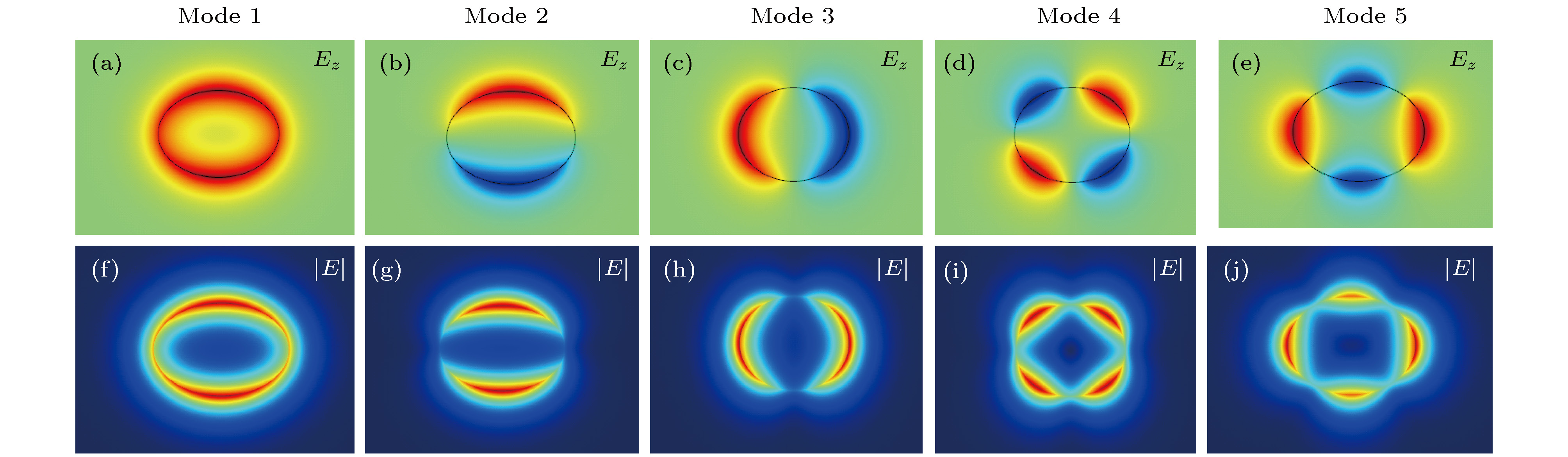 图 2 在a = 110 nm, b = 80 nm,


 图 3 在a = 110 nm, b = 80 nm和


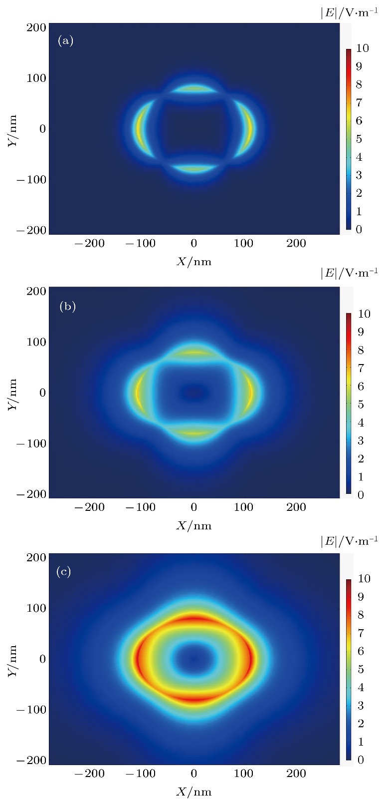 图 4 在a = 110 nm, b = 80 nm和


 图 5 b = 90 nm,


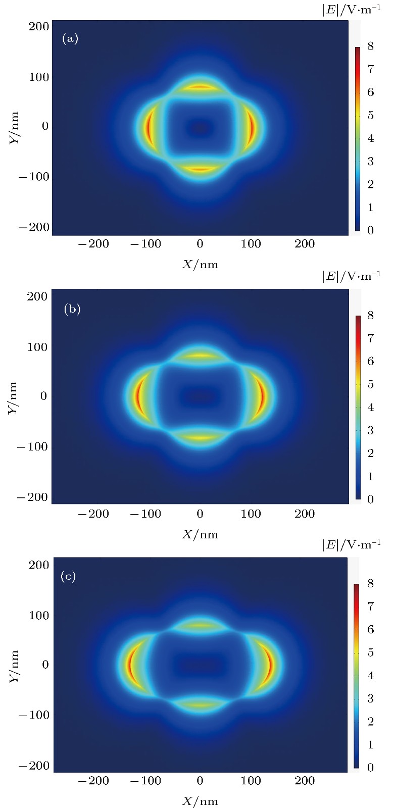 图 6 在b = 80 nm,


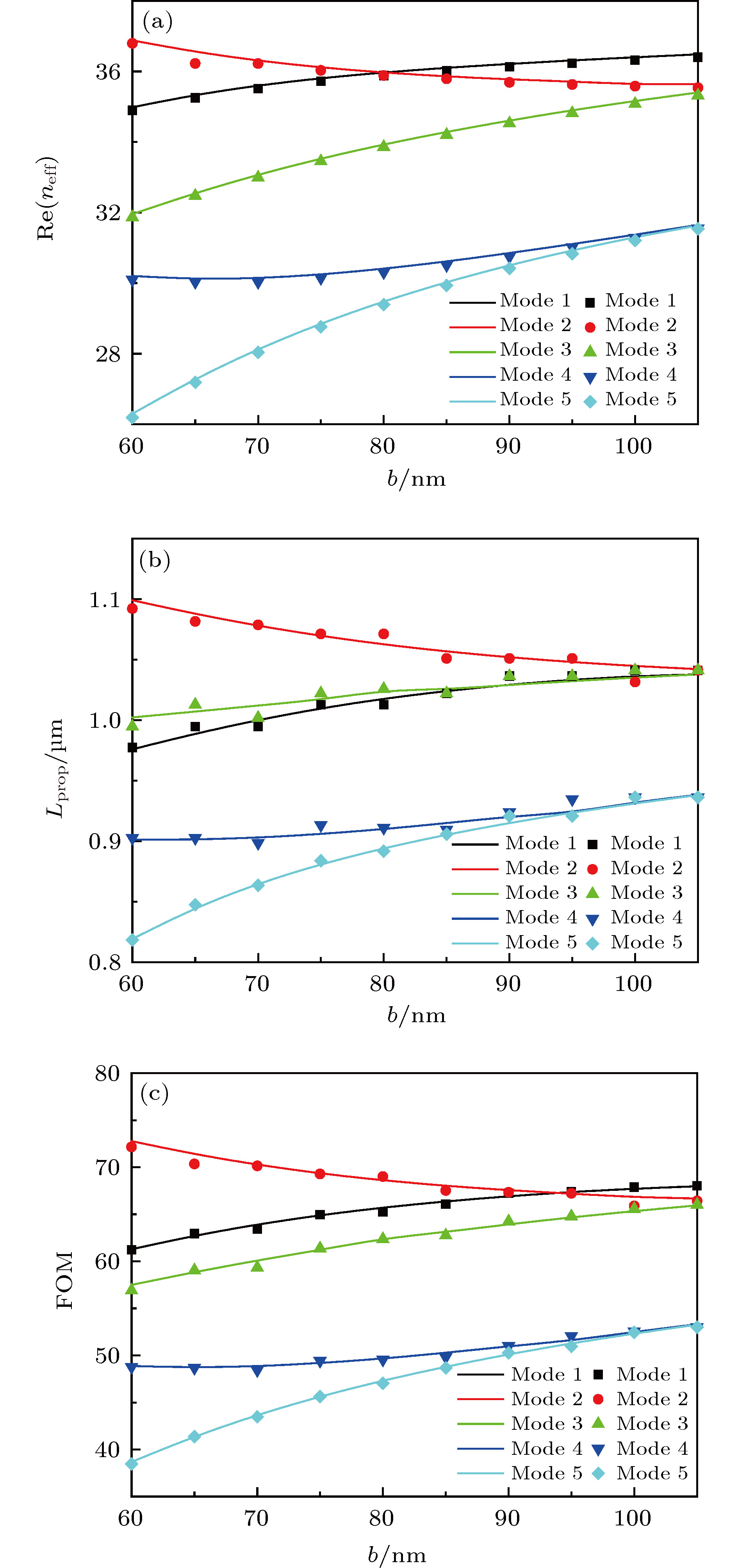 图 7 当a = 110 nm,


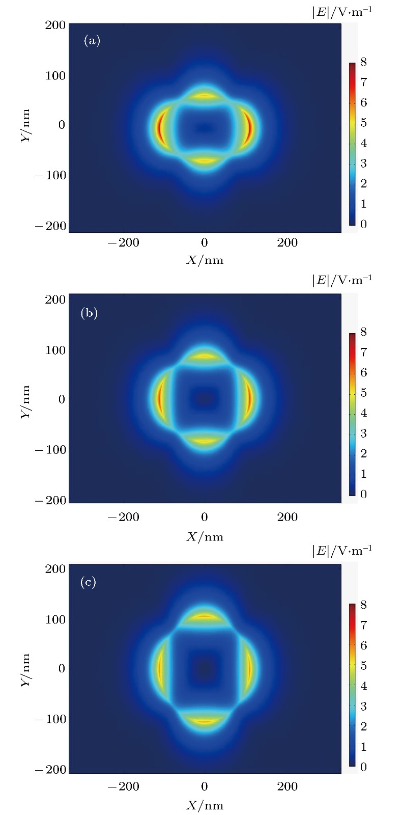 图 8 在a = 110 nm,


 图 9 当a = 110 nm, b = 80 nm和


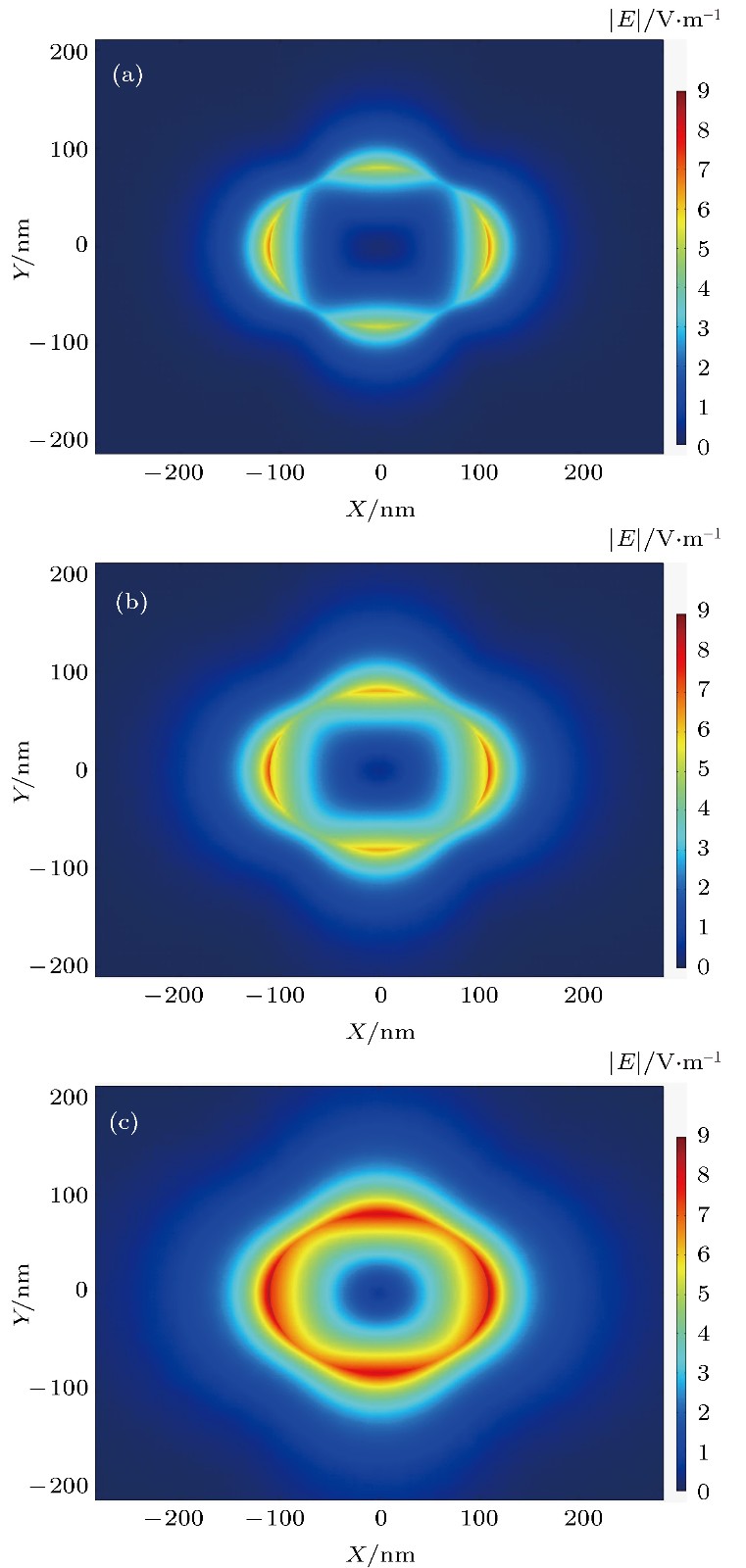 图 10 在a = 110 nm, b = 80 nm和


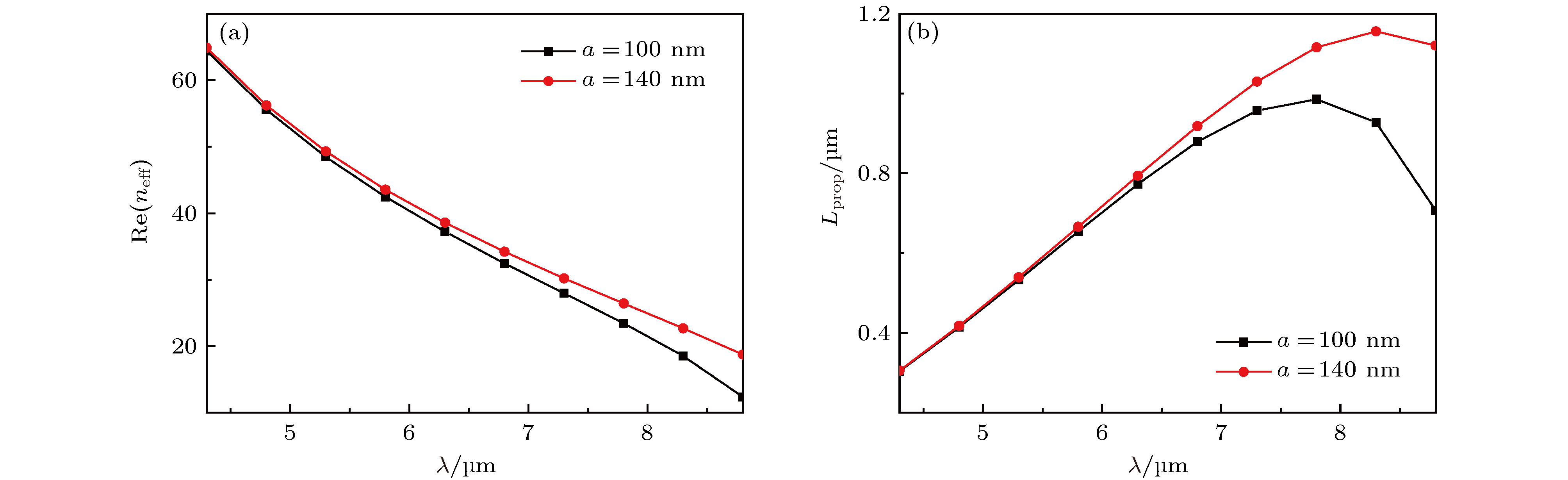 图 11 在


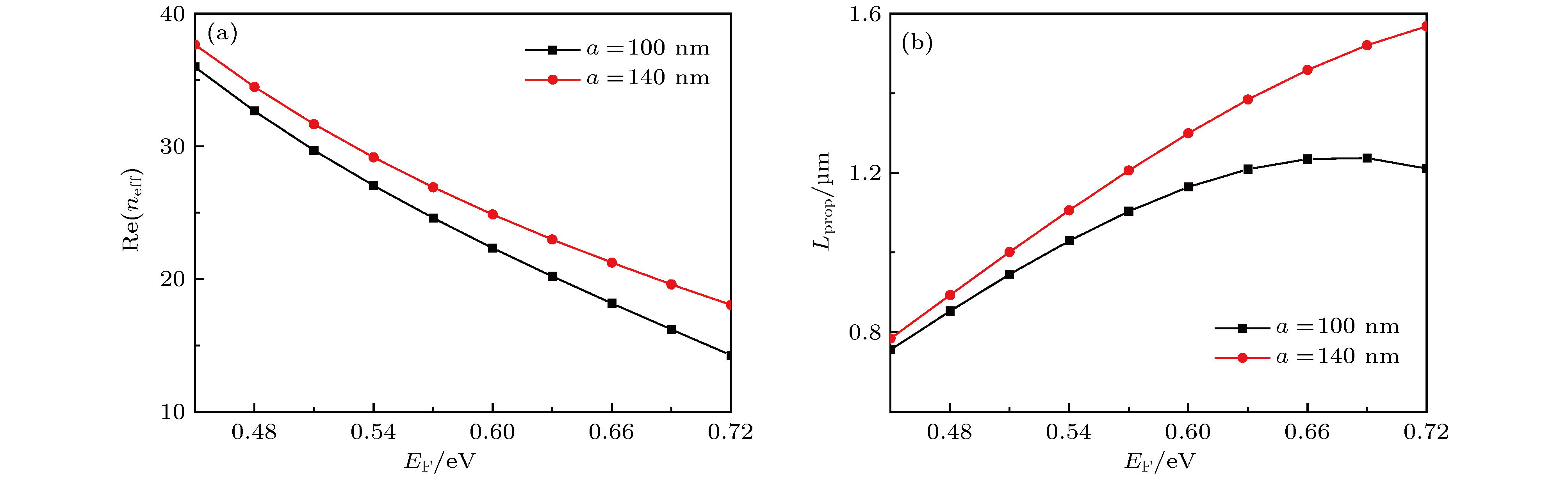 图 12 在b = 100 nm和


