全文HTML
--> --> -->近年来THz波技术发展迅速, 但目前THz波在应用中仍以自由空间光路为主, 自由空间中THz波不易长距离传输, 传输方向也难以控制, 并且自由空间中THz波的传输通常会受到灰尘和水蒸汽的影响[6]. 为了实现THz波的高效传输, 科研工作者提出了多种THz波导, 包括塑料光纤[7]、布拉格光纤[8]、光子晶体光纤[9]和反谐振光纤[6](anti-resonant fiber, ARF)等. 其中ARF利用反谐振效应将入射光束限制在光纤中心的空气孔内进行传输, 以空气为导光介质, 有很低的非线性效应以及很高的损伤阈值. ARF因其结构简单、传输损耗低、损伤阈值高、色散低以及传输带宽高而引起科研工作者的广泛关注[10].
二氧化钒(vanadium, VO2)是一种具有相变性质的金属氧化物, 最大特点是在环境温度达到68 ℃时, 会由单斜结构的绝缘相转变为四方结构的金属相, 在这一过程中其电导率、介电常数等性质都会发生剧烈变化[11]. 除改变环境温度外, 利用光场、电场等外部激励也可以实现VO2的相变, 尤其是利用光调控可以使VO2的相变速度达到皮秒量级[12]. VO2的相变条件低且可控性强, 因而有很广泛的应用空间, 科研工作者将VO2集成至波导内制成多种波导调控器件, 如硅波导振幅调制器[13]、基于硅波导的偏振调控器[14]、光触发纳米级存储器[15]以及等离子体调制器[16]等. 此外, 在近红外波段, VO2与ARF的结合也表现出一定的调制效果, 2020年, Huang等[17]将VO2涂敷于ARF内壁, 利用VO2的相变实现了1550 nm宽带光调制器, 调制深度在60%以上.
VO2在THz波段同样具有非常重要的应用价值, 早在2006年, Jepsen等[18]实验发现, VO2发生相变时, 其对THz波的透过率会发生显著的变化, 证明VO2可应用于诸如光开关、调制器、偏振器等THz器件中. 此后, 利用VO2的相变特性, 研究者们实现了多种THz波调控器件, 如有源宽带THz偏振控制器[19]、宽带THz超材料吸收器[20]、太赫兹编码超表面[21]、可控开环谐振器[22]等.
本文利用有限元分析法研究包层管内壁涂敷有VO2的反谐振光纤(VO2-coated ARF, VO2-ARF), 理论分析VO2相变对VO2-ARF传输特性的影响. 研究VO2的电导率、薄膜厚度以及VO2-ARF包层管壁的厚度对VO2-ARF导光特性的影响. 研究结果表明, VO2发生相变时, VO2-ARF的反谐振周期会发生显著变化, ARF包层管对入射光束的作用效果由反谐振状态变为谐振状态, 在不改变ARF结构的情况下, 仅通过控制VO2的相变便可以实现对ARF内入射光的有效调控. 基于这种原理, 本文提出了一种THz光开关以及一种偏振调控器, 并对其传输特性进行了研究.
2.1.结构设计
利用有限元分析软件COMSOL设计包层管内壁涂敷有VO2的ARF, 结构如图1所示, 该光纤由一定厚度的介质外包层、均匀分布在外包层内壁的6个包层管以及涂敷在包层管内壁的VO2薄膜组成. 光纤外包层壁厚T = 0.5 mm, 包层管直径d = 1.3 mm, 壁厚t = 0.078 mm, 由反谐振条件
 图 1 VO2-ARF结构示意图
Figure1. Cross-section diagram of VO2-ARF.
在VO2-ARF中,包层管内壁涂敷有VO2, VO2薄膜厚度t0为1 μm, 如图1中蓝色部分所示, 为了平衡光纤损耗与光纤的尺寸, 光纤纤芯直径Dcore控制为2 mm. 此光纤用于2.5 THz波的传输与调控, ARF主体材料为环烯烃共聚物(cyclic olefin copolymers, COC), COC是一种具有良好热塑性和高机械强度的聚合物材料, 并且其在THz波段有较低的吸收损耗[23]. ARF利用反谐振效应将入射的THz波限制在中心空气孔内进行传输, 此时模场不依赖材料传输, 材料损耗远小于限制损耗(confinement loss, CL), 光纤的传输损耗以CL为主, ARF中的CL由以下公式进行计算[24]:
VO2的介电常数等参数可通过Drude模型进行计算[20], 在模拟仿真过程中, 以VO2的电导率σ表示其所处状态, VO2由绝缘相向金属相的相变过程中, 电导率会从100 S/m增加至最高3 × 105 S/m.
2
2.2.模拟结果
利用上述VO2-ARF结构, 研究VO2相变对VO2-ARF传输特性的影响. 图2(a)是VO2电导率不同时, VO2-ARF的损耗随包层管壁厚度t的变化曲线. 可以看出, 当VO2电导率由100 S/m变为3 × 105 S/m, 即VO2发生相变时, VO2-ARF的反谐振周期发生分裂, 此时包层管对入射光束的作用效果由反谐振状态变为谐振状态, 光纤的损耗发生突变. 例如, 在t = 78 μm处光纤的损耗由0.5 dB/m增加至100 dB/m以上, 在不改变光纤结构的条件下, 仅控制VO2发生相变, 便可以实现对VO2-ARF损耗的控制. 为了研究这种变化出现的原因, 对比了t = 78 μm时, 不同电导率下光纤的电磁损耗情况, 图2(b)为光纤电磁损耗分布图, 可见, 光纤的电磁损耗主要集中在包层管壁处, 当VO2电导率由100 S/m变为3 × 105 S/m时,包层管壁处的电磁损耗会有3个数量级以上的增加, 由此可知金属相的VO2会产生很高的电磁损耗.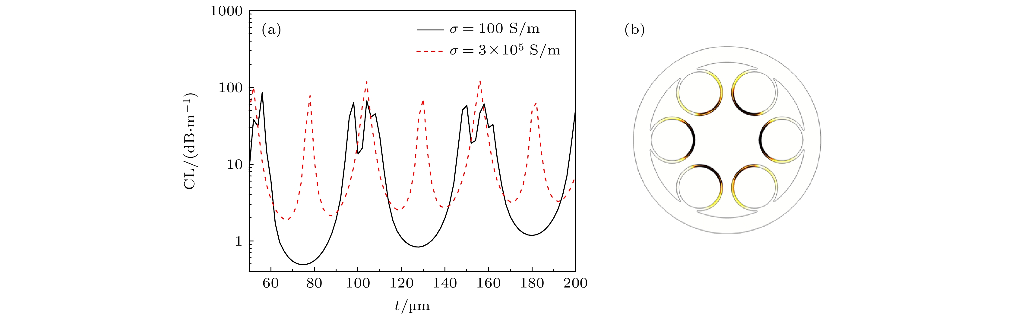 图 2 (a) VO2电导率σ不同时, 光纤的损耗随包层管壁厚t的变化; (b) VO2-ARF电磁损耗分布
Figure2. (a) Confinement loss (CL) of VO2-ARF as a function of cladding tube wall thickness (t) under different conductivity of VO2 (σ); (b) electromagnetic loss distribution of VO2-ARF.
进一步研究VO2的电导率与厚度对VO2-ARF反谐振周期的影响. VO2厚度t0 = 1 μm时, 光纤的损耗随VO2-ARF包层管壁厚度以及VO2电导率的变化如图3(a)所示. 可以看出, 随着电导率的增加, 在t = 60 μm附近反谐振周期中开始出现额外的高损耗点, 并且该高损耗点随着电导率的增加而右移, 损耗也随之增加, 在这一过程中, 包层管对光束的作用效果由反谐振状态变为谐振状态. 在VO2电导率增加的过程中, VO2会由最初的绝缘相向金属相过渡, 当电导率大于6 × 10⁴ S/m后, VO2由金属相占主导, 随着电导率的继续增加, 高损耗点不再发生变化.
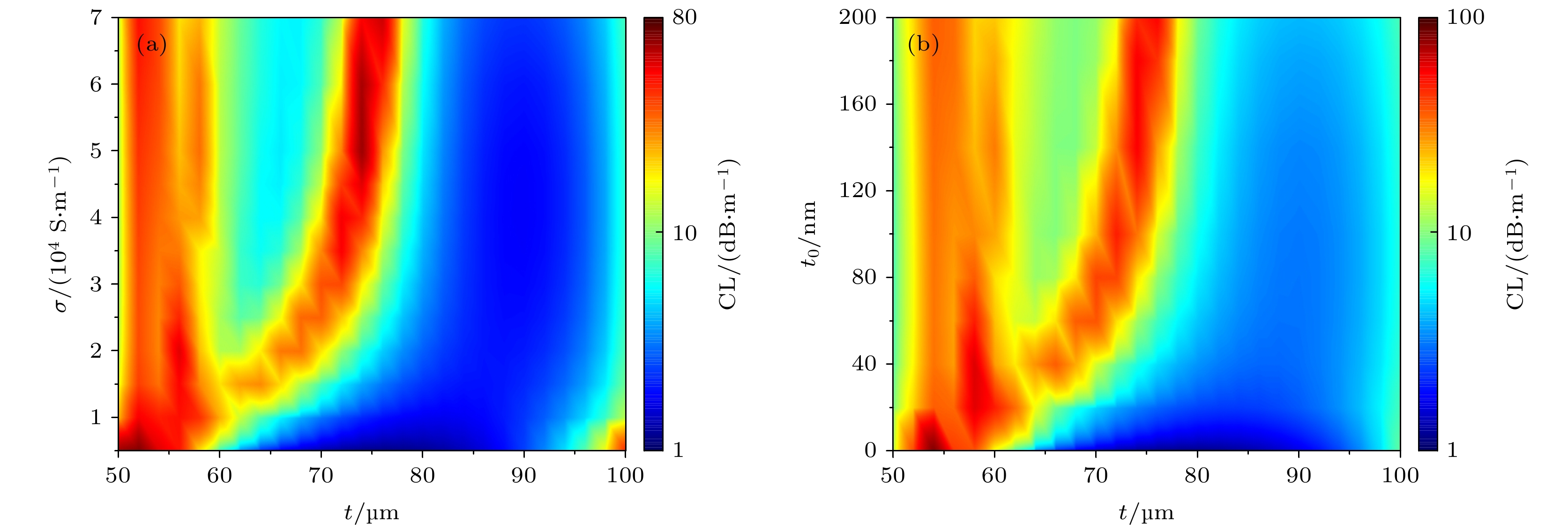 图 3 (a) VO2-ARF的损耗随包层管壁厚t以及VO2电导率σ的变化; (b) VO2-ARF损耗随包层管壁厚t以及VO2厚度t0的变化
Figure3. Confinement loss (CL) of VO2-ARF as a function of cladding tube wall thickness (t) and the conductivity of VO2 (σ); (b) confinement loss (CL) of VO2-ARF as a function of cladding tube wall thickness (t) and the thickness of VO2 (t0).
当VO2电导率设置为最大值3 × 10⁵ S/m时, 光纤损耗随VO2-ARF包层管壁厚度以及VO2厚度的变化如图3(b)所示. 此时VO2为金属相, 由图3(b)可见, 当VO2厚度较小时, VO2-ARF的反谐振周期并没有受到VO2的影响, 较薄的VO2对VO2-ARF传输特性几乎没有影响, 其金属相的性质并没有表现出来. 随着VO2厚度的增加, 在t = 65—80 μm范围内, 反谐振周期中开始出现高损耗点, 并且高损耗点随着VO2厚度的增加出现右移, 损耗也随之增加, 当VO2厚度大于160 nm后, 异常的高损耗点便不再受到VO2厚度的影响, 此时包层管对光束的作用效果为谐振状态. 可见, 在ARF包层管内壁涂敷一层厚度足够的VO2, 通过控制VO2的相变, 便可实现对ARF包层管反谐振状态的调控, 利用该原理, 本文提出了一种基于VO2-ARF的THz光开关和一种偏振调控器.
3.1.光开关
根据VO2相变调控VO2-ARF反谐振周期的原理, 本文提出了基于VO2-ARF的THz光开关. 光开关的三维结构如图4(a)所示, 外包层壁厚T = 0.5 mm, 6个包层管均匀分布在外包层内壁, 包层管内径d = 1.3 mm, 壁厚t = 0.078 mm, 包层管内壁涂敷有VO2, 如图4(a)中蓝色部分所示, VO2厚度t0 = 1 μm, 考虑到光纤的尺寸及损耗, 控制纤芯直径Dcore = 2 mm, 光开关长度为10 cm. 利用光调控的方法, 可实现对VO2相变的高速调控, Liu等[12]利用800 nm的脉冲激光对VO2进行光激励, 使其发生快速相变, 研究VO2的光学特性, 这一过程中800 nm脉冲激光会使VO2发生带间跃迁, 改变其光学特性. 根据上述研究, 本文采用波长为800 nm的脉冲激光器作为激励光源, 脉冲宽度为纳秒级, 激光能量密度不小于100 μJ/cm2, 控制6个包层管处激励光源分别入射至各包层管内, 使激励光源能够均匀辐照位于包层管内部的VO2, 控制其相变情况. 激励光源的通断对光纤损耗的影响如图4(b)所示, 激励光源关闭时, VO2为绝缘相, 此时光纤的损耗随波长的变化如图4(b)中黑色曲线所示, 光纤内电场分布如图4(c)所示, 可见THz波被有效限制在纤芯中进行传输. 激励光源打开, 诱导VO2发生相变后, ARF的损耗在入射光波长接近120 μm时发生剧烈变化, 此时光纤中的电场分布如图4(d)所示, 可见此时入射光与包层管壁发生强烈耦合, 致使光纤损耗急剧增加. 对波长约为120 μm的入射光, 激励光源打开与关闭状态下的损耗分别为0.5 dB/m和110 dB/m, 可见, 该光开关可实现对2.5 THz波有效的“开”与“关”的效果. 图 4 (a) 光开关结构示意图; (b) 光开关处于“开”、“关”状态时, 光纤损耗随波长λ的变化曲线; (c) 光开关为开状态和(d)关状态时的电场分布图
Figure4. (a) Cross-section diagram of optical switch; (b) when the optical switch is on and off, confinement loss (CL) of ARF as a function of incident light wavelength (λ); electric field distribution diagram when optical switch is (c) on and (d) off.
2
3.2.偏振调控器
基于VO2-ARF的研究, 本文提出了如图5(a)所示的偏振调控器, 外包层壁厚T = 0.5 mm, 4个包层管均匀分布在外包层内壁, 分别命名为1, 2, 3, 4, 包层管内径d = 2 mm, 壁厚t = 0.078 mm, 包层管内壁涂敷有VO2, 如图5(a)中蓝色部分所示, VO2厚度t0 = 1 μm, 控制纤芯直径Dcore = 2 mm, 光纤入射光为2.5 THz波. 与光开关相同, 偏振调控器同样使用波长为800 nm脉冲激光诱导VO2发生相变, 从而达到调控效果. 分别控制光纤4个包层管内部激励光源的通断以控制不同包层管内VO2的相变情况, 使光纤的不同偏振方向处于不同的谐振状态, 因而光纤不同偏振方向的有效折射率及损耗会产生很大的差别, 入射的THz波会转变为偏振光, 且偏振方向可控. 图 5 (a) 偏振调控器结构示意图; (b) 光纤实现偏振光传输时, 光纤不同偏振方向的有效折射率随激励光源光通量的变化曲线; (c) 光纤实现偏振光传输时, 光纤不同偏振方向的损耗随激励光源光通量的变化曲线
Figure5. (a) Cross-section diagram of polarization controller; (b) effective refractive index (neff) and (c) confinement loss (CL) of ARF in orthogonal polarization directions as a function of excitation fluences of the excitation laser when ARF realizes the polarized transmission.
将包层管1, 2内激励光源打开, 同时关闭3, 4内激励光源时, 此时x, y偏振方向光纤的有效折射率与损耗随激励光源光通量的变化如图5(b)和图5(c)所示, 在光通量较低时, VO2为绝缘相, 可见此时光纤不同偏振方向的有效折射率与损耗几乎无差别. 随着包层管1, 2内激励光源光通量的增加, 光纤的双折射系数Δn (

