Fund Project:Project supported by the National Key R&D Program of China (Grant No. 2017YFC1405605), the Innovation Youth Fund of the Ocean Telemetry Technology Innovation Center of the Ministry of Natural Resources, China (Grant No. 21k20190088), the Natural Science Foundation of Inner Mongolia, China (Grant No. 2018MS01005), and the Graduate Students’ Scientific Research Innovation Fund Program of Inner Mongolia Normal University, China (Grant No. CXJJS19098)
Received Date:04 June 2020
Accepted Date:26 July 2020
Available Online:27 November 2020
Published Online:20 December 2020
Abstract:According to the conformal mapping from the exterior region of the regular n-polygon hole to the exterior region of a unit circle and from the exterior region of four cracks emanating from a circle to the interior region of a unit circle, a new conformal mapping is constructed to map the exterior region of four cracks emanating from a regular 4n-polygon hole to the interior of a unit circle. Then, based on the Gurtin-Murdoch surface/interface model and complex method, the anti-plane fracture of four nano-cracks emanating from a regular 4n-polygon nano-hole in magnetoelectroelastic material is studied. The exact solutions of stress intensity factor, electric displacement intensity factor, magnetic induction intensity factor, and energy release rate are obtained under the boundary condition of magnetoelectrically impermeable with considering the surface effect. Without considering the effect of the surface effect, the exact solution of four cracks emanating from a regular 4n-polygon hole in a magnetoelectroelastic material can be obtained. The numerical results show the influences of surface effect and the size of defect on the stress intensity factor, electric displacement intensity factor, magnetic induction intensity factor and energy release rate under the magnetoelectrically impermeable boundary condition. It can be seen that the stress intensity factor, electric displacement intensity factor, and magnetic induction intensity factor are significantly size-dependent when considering the surface effects of the nanoscale defects. And when the size of defect increases to a certain extent, the influence of surface effect begins to decrease and finally tends to follow the classical elasticity theory. When the distance between the center and the vertex of the regular 4n-polygon nano-hole is constant, the dimensionless field intensity factor decreases gradually with the increase of the number of edges, and approaches to the conclusion of a circular hole with four cracks. With the increase of the relative size of the crack, the dimensionless field intensity factor increases gradually. The dimensionless energy release rate of the nanoscale cracked hole has a significant size effect. The increase of mechanical load will increase the normalized energy release rate. The normalized energy release rate first decreases and then increases with electrical load increasing. The normalized energy release rate decreases with magnetic load increasing. Keywords:magnetoelectroelastic materials/ surface effect/ nanoscale
5.数值分析根据文献[18], 取磁电弹性材料作为基体, 材料常数为$ c_{44} = 44 $ GPa, $ e_{15} = 5.8 $ C/m2, $\varepsilon_{11} = 5.64 \times 10^{-9}$ C2/(N·m2), $ h_{15} = 275 $ N/(A·m), $\beta_{11} = 5000 \times10^{-9}$ N·s/(V·C), $ \mu_{11} = 297 \times10^{-6} $ (N·s2)/C2. 假设表面层由压磁材料构成[18], $ c_{44}^{\rm S} = 10 $ N/m, $\varepsilon_{11}^{\rm S} \!=\! 0.03 \!\times\! 10^{-18}$ C2/(N·m), $h_{15}^{\rm S} \!=\! 330 \times 10^{-9}$ N/A. 图3—5分别给出了在磁电非渗透边界条件下考虑表面效应时, 只受机械载荷作用、只受电载荷作用和只受磁载荷作用下的裂纹尖端应力强度因子随正$ 4 n $边形孔尺寸的变化. 在经典弹性理论中, 应力强度因子只与机械载荷的变化有关. 而从图中看出在纳米尺度下, 应力强度因子还受到电载荷和磁载荷的影响, 这与经典弹性理论中具有明显的差异. 所以可以得出结论, 表面效应会使磁、电、弹性场耦合. 从图3可以看出, 当$ a = 0 $ nm时$ K_{\tau}^*/\tau_{32}^{\infty} $也趋于$ 0 $, 而随着$ a $的增大$ K_{\tau}^*/\tau_{32}^{\infty} $也逐渐增大, 最终趋于2, 即趋于经典弹性理论中的结论. 图4和图5表明当$ a = 0 $ nm时, 表面效应的影响非常小($ K_{\tau}^*/D_2^{\infty} $和$ K_{\tau}^*/B_2^{\infty} $趋于0), 而当边长$ a $在纳米尺度逐渐增加时, 缺陷的表面积与体积的比值变得非常大, 表面效应的影响也非常大. 此时$ K_{\tau}^*/D_2^{\infty} $随着$ a $的增加迅速增大, 而$ K_{\tau}^*/B_2^{\infty} $随着$ a $的增加迅速减小, 之后随着孔口的不断增加表面效应的影响开始逐渐减小, 最终趋于经典弹性理论中的结论. 图 3 只受机械载荷作用时表面效应对应力强度因子的影响 Figure3. Surface effect on the stress intensity factor near the crack tip induced by anti-plane mechanical load $\tau_{32}^{\infty}$ only
图 4 只受电载荷作用时表面效应对应力强度因子的影响 Figure4. Surface effect on the stress intensity factor near the crack tip induced by in-plane electrical load $D_2^{\infty}$ only
图 5 只受磁载荷作用时表面效应对应力强度因子的影响 Figure5. Surface effect on the stress intensity factor near the crack tip induced by in-plane magnetic load $B_2^{\infty}$ only
图6—8分别给出了只受机械载荷作用、只受电载荷作用和只受磁载荷作用下的裂纹尖端电位移强度因子随正$ 4 n $边形孔尺寸的变化. 而从图中可以看出, 在纳米尺度下, 电位移强度因子还受到机械载荷和磁载荷的影响, 所以可以得出同样的结论, 表面效应会使磁、电、弹性场耦合. 从图6可知, $ K_{D}^*/\tau_{32}^{\infty} $随着$ a $的增大而减小, 最终趋于0. 图7表明$ K_{D}^*/D_2^{\infty} $随着$ a $迅速减小并趋于经典弹性理论中的结论, 可以看出当表面层选为压磁材料时电载荷对于电位移强度因子的影响只在$ a $很小时有显著的影响. 图8表明当$ a = 0 $ nm时, $ K_{D}^*/B_2^{\infty} $趋于$ 0 $, 而当边长$ a $在纳米尺度逐渐增加时, 此时$ K_{D}^*/B_2^{\infty} $随着$ a $的增加迅速减小. 之后表面效应的影响开始逐渐减小, 此时$ K_{D}^*/B_2^{\infty} $逐渐增加, 最终趋于经典弹性理论中的结论. 图 6 只受机械荷作用时表面效应对电位移强度因子的影响 Figure6. Surface effect on the electric displacement intensity factor near the crack tip induced by anti-plane mechanical load $\tau_{32}^{\infty}$ only
图 7 只受电载荷作用时表面效应对电位移强度因子的影响 Figure7. Surface effect on the electric displacement intensity factor near the crack tip induced by in-plane electrical load $D_2^{\infty}$ only
图 8 只受磁载荷作用时表面效应对电位移强度因子的影响 Figure8. Surface effect on the electric displacement intensity factor near the crack tip induced by in-plane magnetic load $B_2^{\infty}$ only
图9—11分别给出了在磁电非渗透边界条件下考虑表面效应时, 只受机械载荷作用、只受电载荷作用和只受磁载荷作用下的裂纹尖端电位移强度因子随正$ 4 n $边形孔尺寸的变化. 从图中可以看出, 在纳米尺度下, 电位移强度因子受到机械载荷、电载荷和磁载荷的影响, 进一步印证了表面效应会使磁、电、弹性场耦合. 图9和图10表明当$ a = 0 $ nm时, 表面效应的影响非常小($ K_{B}^*/\tau_{32}^{\infty} $和$ K_{B}^*/D_2^{\infty} $趋于$ 0 $), 而当边长$ a $在纳米尺度逐渐增加时, 缺陷的表面积与体积的比值变得非常大, 而后逐渐减小, 此时$ K_{B}^*/\tau_{32}^{\infty} $和$ K_{B}^*/D_2^{\infty} $随着$ a $的增加迅速减小. 之后随着孔口表面积与体积的比值逐渐减小, 表面效应的影响开始逐渐减小, 此时$ K_{B}^*/\tau_{32}^{\infty} $和$ K_{B}^*/D_2^{\infty} $随着$ a $的增加逐渐增加, 最终趋于经典弹性理论中的结论. 图11表明$ K_{B}^*/B_{2}^{\infty} $随着$ a $的增加迅速增大并趋于经典弹性理论的结果. 这说明当表面层选为压磁材料时, 磁载荷只在$ a $很小时才对磁感应强度因子有显著影响. 图 9 只受机械载荷作用时表面效应对磁感应强度因子的影响 Figure9. Surface effect on the magnetic induction intensity factor near the crack tip induced by anti-plane mechanical load $\tau_{32}^{\infty}$ only
图 10 只受电载荷作用时表面效应对磁感应强度因子的影响 Figure10. Surface effect on the magnetic induction intensity factor near the crack tip induced by in-plane electrical load $D_2^{\infty}$ only
图 11 只受磁载荷作用时表面效应对磁感应强度因子的影响 Figure11. Surface effect on the magnetic induction intensity factor near the crack tip induced by in-plane magnetic load $B_2^{\infty}$ only
图12给出了当$ n = 1 $, 即缺陷为带四条裂纹的正方形孔, 不考虑表面效应时无量纲场强度因子随右侧裂纹长度的变化. 从图12可以看出, K随着右侧裂纹长度的增加而增加, 这就是说右侧裂纹长度增加会促进裂纹的扩展. 图13给出了无量纲场强度因子随正多边形边的数量的变化, 可以看出当裂纹长度为$ a = L_1 = 0.02 $ m, $ L_2 = 0.03 $ m, $L_3 = 0.04$ m时, 带四条裂纹的孔口为正方形时应力强度因子最大. 随着$ n $的增加正$ 4 n $边形的形状越来越接近圆形, 此时应力强度因子逐渐减小, 最终趋于带四条裂纹的圆孔的应力强度因子. 从图13可以看出, 正$ 4 n $边形边的数量越小, 缺陷扩展得越快. 图14给出了无量纲能量释放率$ J/J_0 $随$ a $的变化, 其中$ J_0 $表示不考虑表面效应时的能量释放率. 从图14可以看出, 在纳米尺度下考虑表面效应的影响, $ J/J_0 $随$ a $的增加而增大, 最终趋于经典弹性理论. 图 12 无量纲应力强度因子随右侧裂纹长度变化 Figure12. Variations of the dimensionless stress intensity factor at crack tip with the crack length $L_1$
图 13 无量纲应力强度因子随n的变化 Figure13. Variations of the dimensionless stress intensity factor at crack tip with n
图 14 无量纲能量释放率随孔口尺寸的变化 Figure14. Variations of the dimensionless energy release rate with the size of the cracked hole


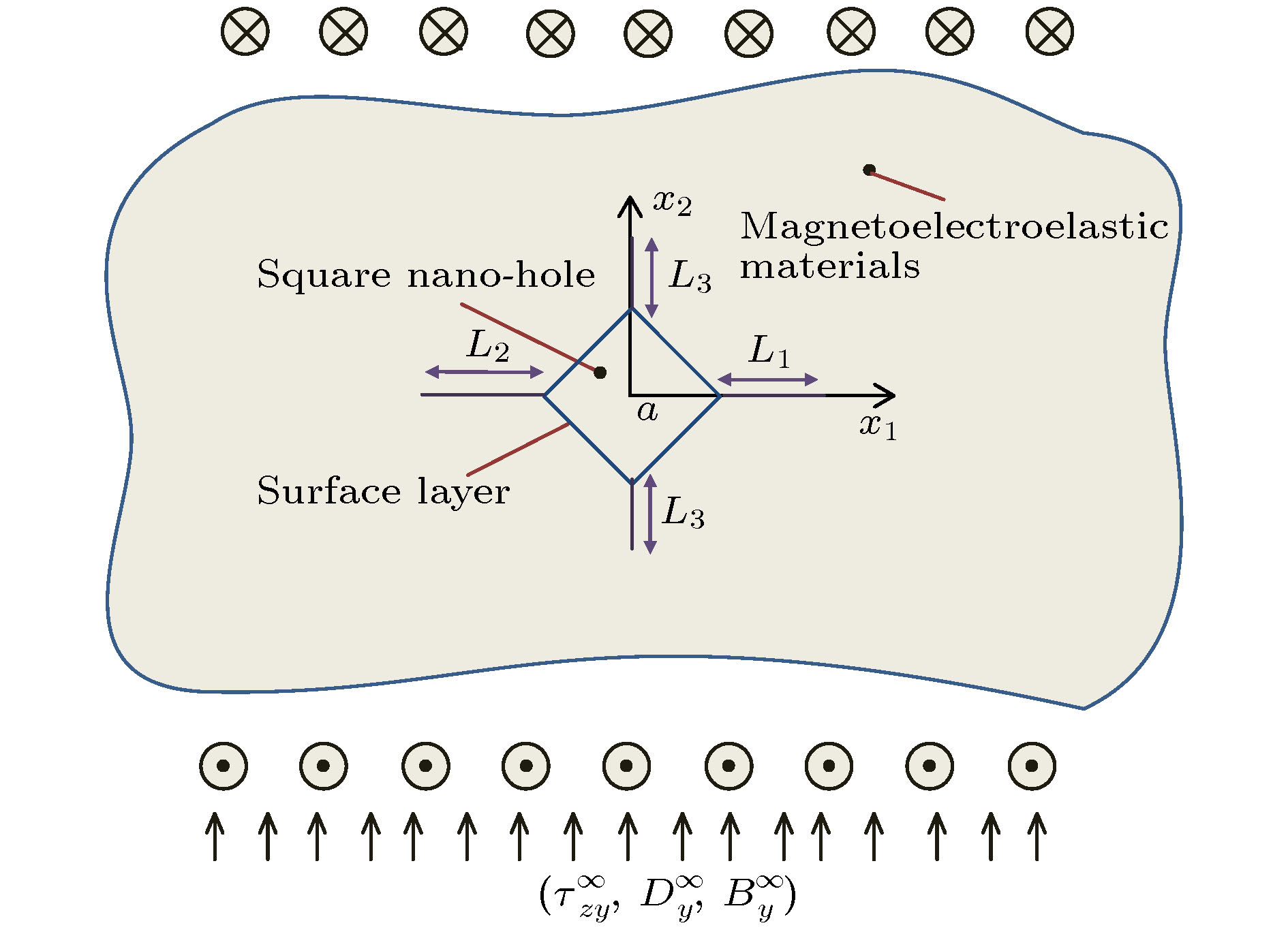 图 1 磁电弹性材料中含有带四条裂纹的正方形孔


 图 2 保角变换


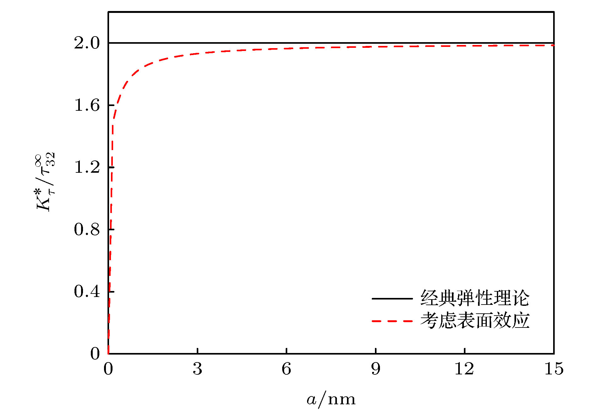 图 3 只受机械载荷作用时表面效应对应力强度因子的影响
 图 4 只受电载荷作用时表面效应对应力强度因子的影响
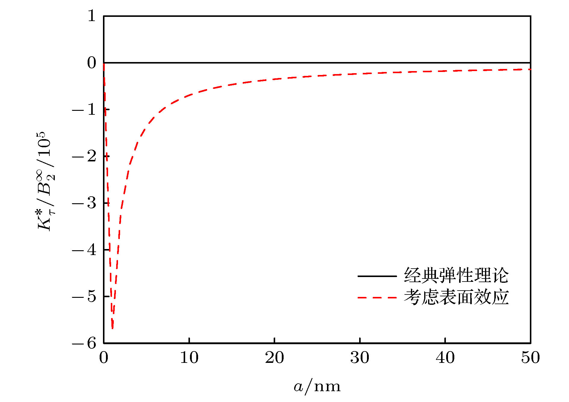 图 5 只受磁载荷作用时表面效应对应力强度因子的影响


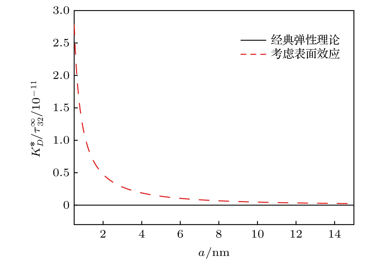 图 6 只受机械荷作用时表面效应对电位移强度因子的影响
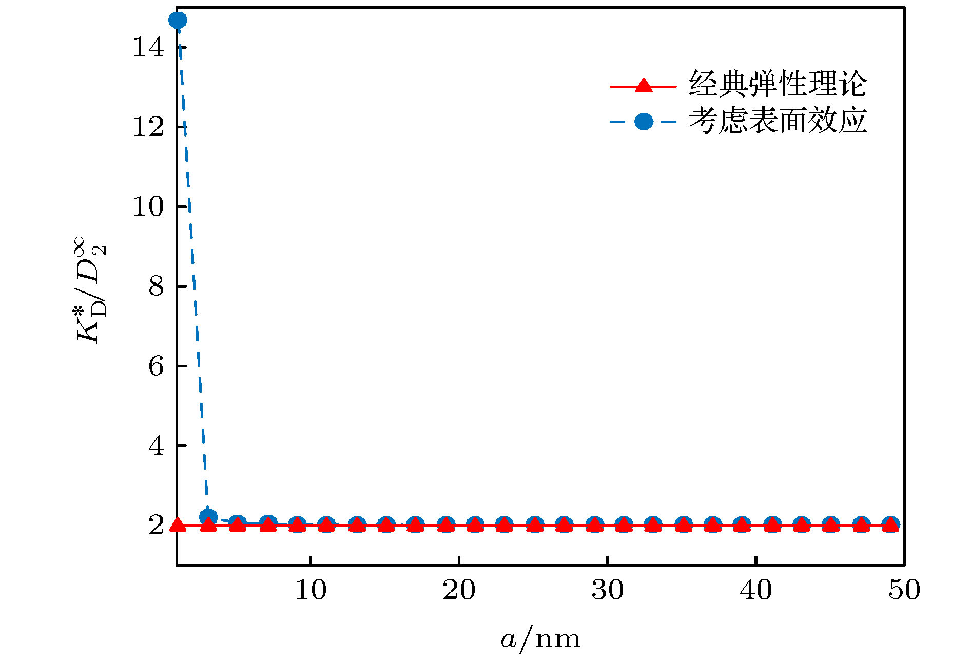 图 7 只受电载荷作用时表面效应对电位移强度因子的影响
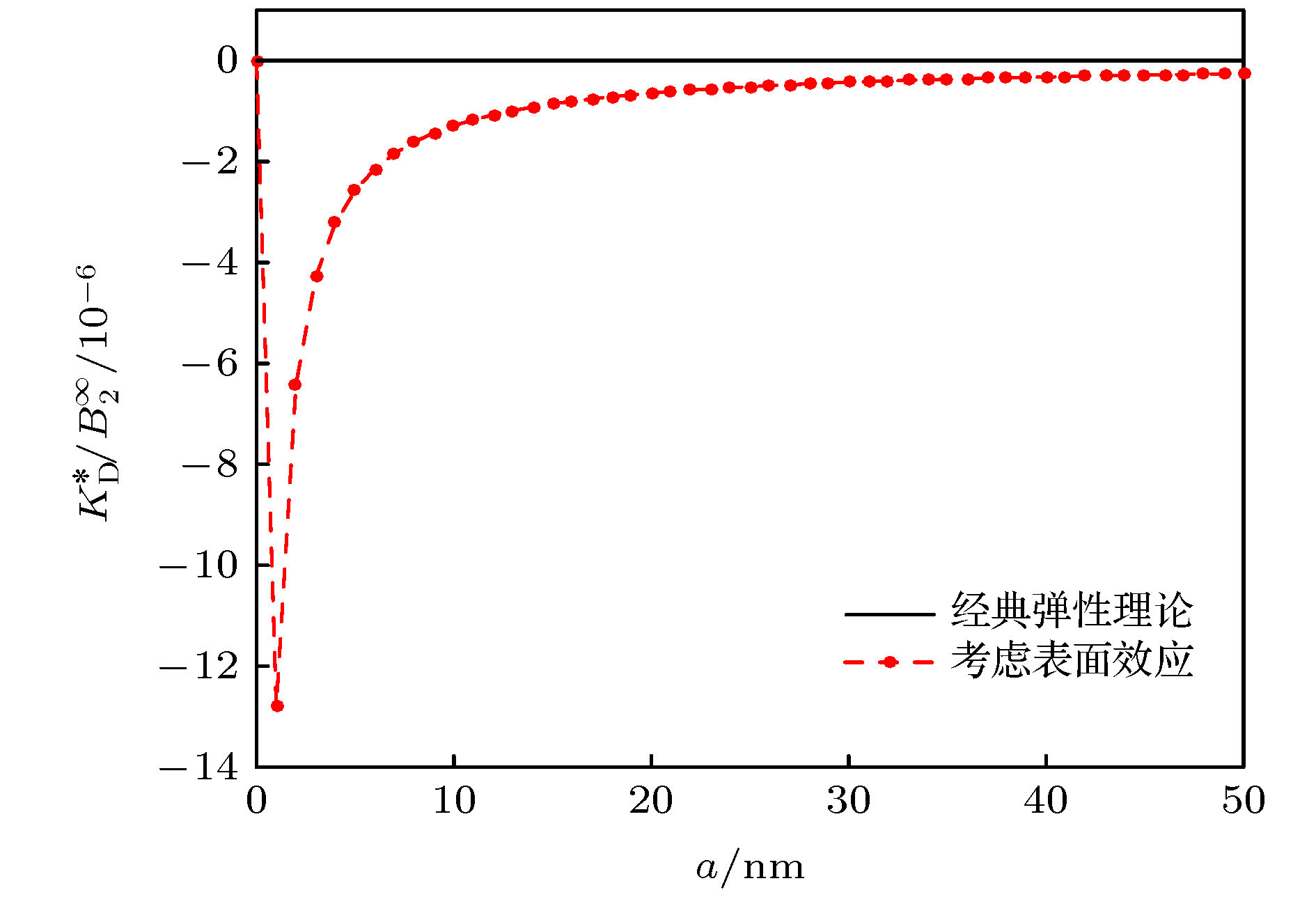 图 8 只受磁载荷作用时表面效应对电位移强度因子的影响


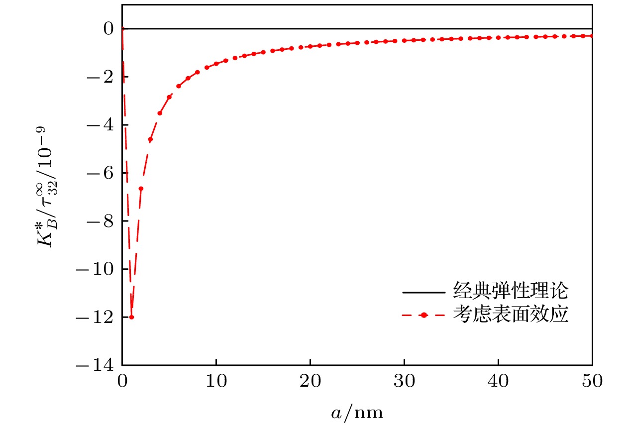 图 9 只受机械载荷作用时表面效应对磁感应强度因子的影响
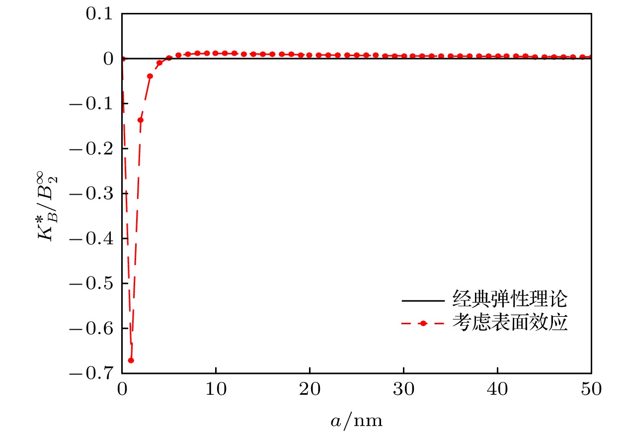 图 10 只受电载荷作用时表面效应对磁感应强度因子的影响
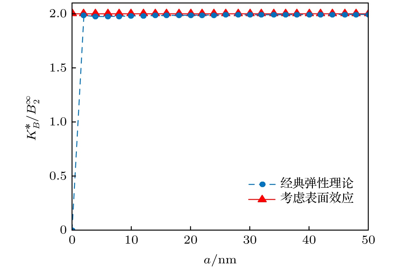 图 11 只受磁载荷作用时表面效应对磁感应强度因子的影响


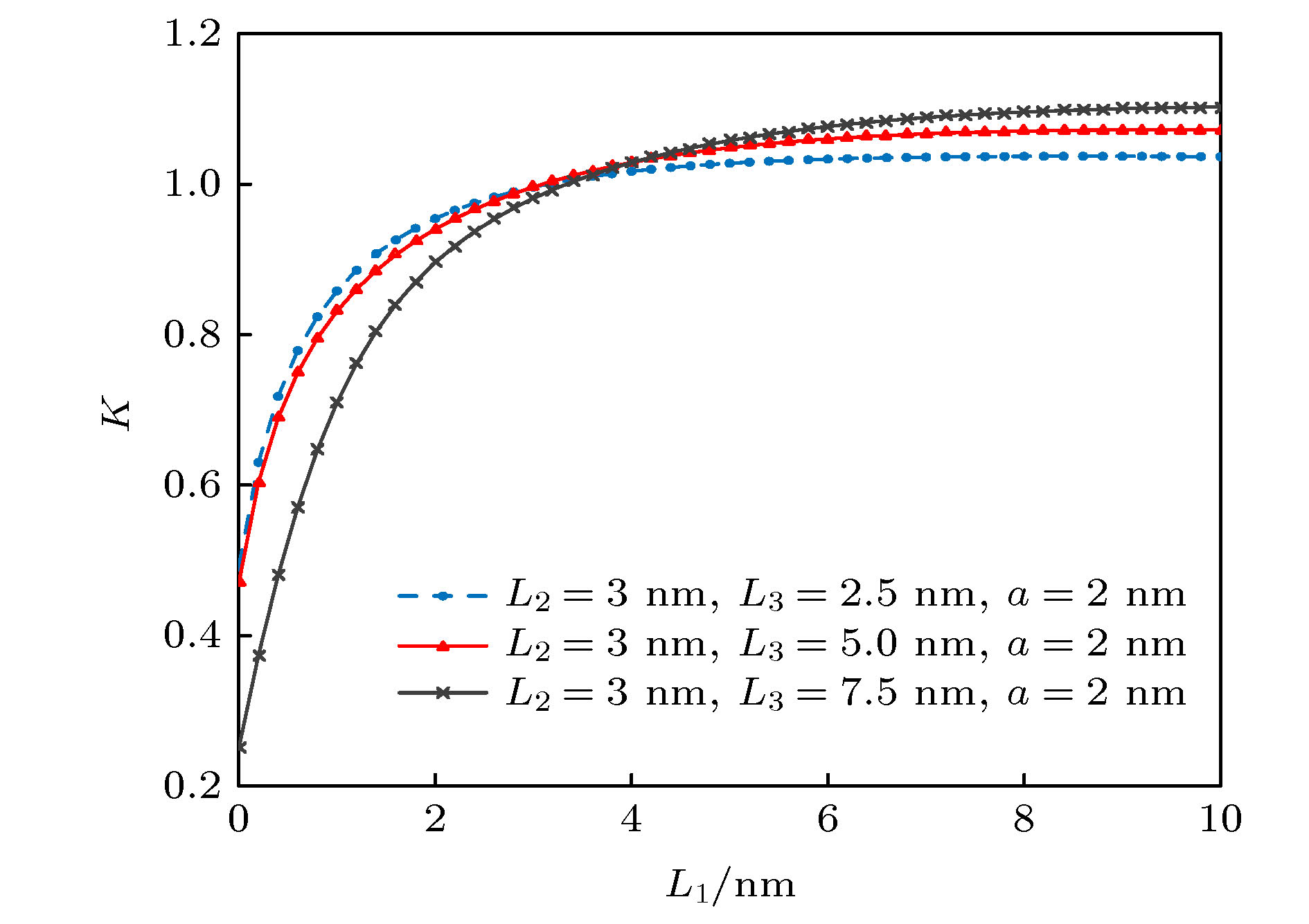 图 12 无量纲应力强度因子随右侧裂纹长度变化
 图 13 无量纲应力强度因子随n的变化
 图 14 无量纲能量释放率随孔口尺寸的变化


 图 15 正则化能量释放率随机械载荷的变化
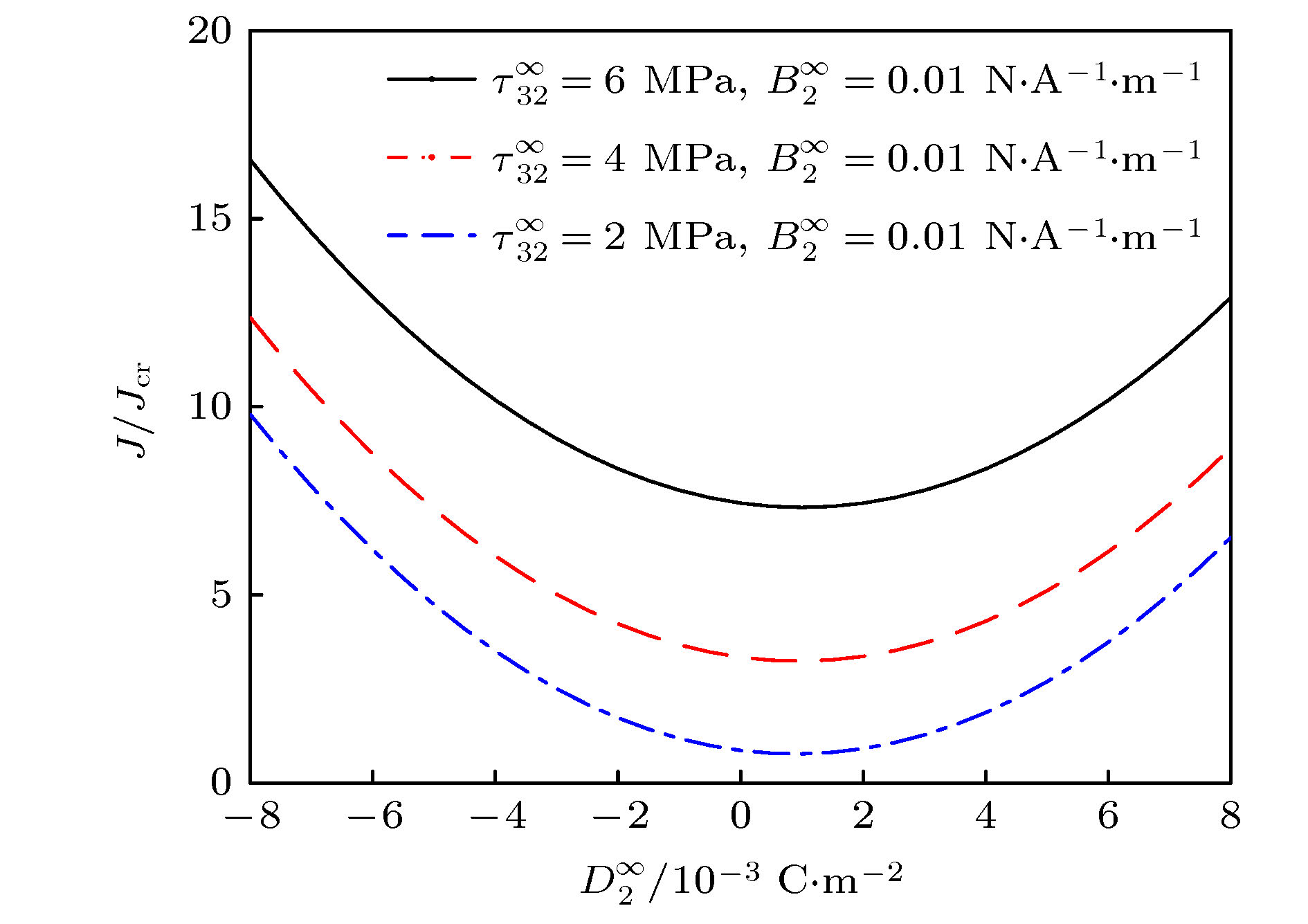 图 16 正则化能量释放率随电载荷的变化
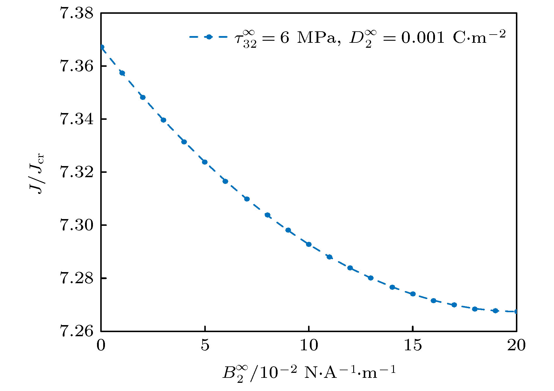 图 17 正则化能量释放率随磁载荷的变化


