1.Department of Foundation, Air Force Engineering University, Xi’an 710051, China 2.Department of Wired Communications, Air Force Communications NCO Academy, Dalian 116100, China
Abstract:Recently, the operating frequency of nanomagnetic logic device has reached the spin wave frequency of nanomagnets. Therefore, the dynamic magnetic properties of nanomagnets, which are excited by microwave magnetic field, have been explored by many researchers. In this paper, the micro-magnetic model of asymmetric strip nanomagnets under microwave excitation is established. By using the anisotropic stress field (along the x-axis direction) that is generated by a constant voltage and the SINC function microwave magnetic field (along the y-axis direction) to excite the nanomagnets at the same time, the effects of tilt angle and defect angle on the ferromagnetic resonance (FMR) spectrum and spin wave mode of the asymmetric strip nanomagnets are studied. Spectral analysis is performed on the micromagnetic simulation data. Simulation results show that as the tilt angle of the asymmetric strip nanomagnet increases, the ferromagnetic resonance frequency increases. What is more, this phenomenon is independent of the defect angle of the nanomagnet. When the tilt angle is constant, there exists a monotonically increasing relation between the ferromagnetic resonance frequency of the asymmetric strip nanomagnet and the defect angle. The spin wave modes of the nanomagnets differ a lot as defect angle changes. The asymmetric strip nanomagnet is compared with the rectangle nanomagnet, and the spin wave mode of the asymmetric strip nanomagnet is localized. Specifically, the spin wave mode of the asymmetric strip nanomagnets is asymmetric and the high precession region exists at the edge, which is termed asymmetric edge mode. The changes of the tilt angle lead to the changes in the demagnetizing field inside the nanomagnet, which gives rise to the movement of the edge mode. However, the center mode is not sensitive to the change of tilt angle. Finally, the magnetic loss of the model under the excitation of high frequency microwave magnetic field is analyzed and the reliability of the model is verified. These findings indicate that the defect angle and tilt angle can be used to tune the spin wave mode and the ferromagnetic resonance frequency of nanomagnets, and thus providing an important theoretical basis for designing the tunable microwave nanomagnetic devices. Keywords:asymmetric strip nanomagnet/ ferromagnetic resonance (FMR)/ spin wave mode/ microwave devices
2.模型结构建立利用微磁仿真软件OOMMF[30]对具有不同缺陷角和倾斜角的非对称条形纳磁体的铁磁共振谱和自旋波模式的空间分布进行了仿真分析. 为了确定FMR频率, 同时对纳磁体施加满足sinc函数的微波激励和外加电压产生的应力. 结构如图1(a)所示. 图 1 (a) 微波磁场和应力各向异性场相互垂直激励纳磁体的结构示意图, 此图中纳磁体未倾斜; (b) 纳磁体的俯视图, θ是缺陷角度, φ是纳磁体长轴和y轴之间的倾斜角度 Figure1. (a) Schematic illustration of nanomagnet excited by perpendicular microwave magnetic field and bias magnetic field, the magnet in this figure is not tilted; (b) top view of nanomagnet, where θ is the defect angle and φ is the tilt angle between y-axis and the long axis of nanomagnets.
式中 μ0H0 = 5 mT, f = 15 GHz, μ0 = 4π × 10–7 N/A2是真空中磁导率, 同时施加与微波磁场相互垂直的μ0Hstress = 100 mT恒定应力各向异性场. 在微磁仿真中采用的网格大小为4 nm × 4 nm × 4 nm. 根据交换距离公式得到的网格距[30]${l_{{\rm{ex}}}}=\sqrt {{{2 A} / {({\mu _0}{M_{\rm{s}}}^2)}}} \approx 6.8\;{\rm{ nm}}$, 但由于OOMMF软件对模型定义的限制并不能选择7 nm作为网格距离. 网格划分在缺角部位产生的锯齿状会造成部分磁矩丢失, 这会导致仿真中的材料交换能低于真实材料的交换能. 选用4 nm的网格距离满足了OOMMF软件对模型的定义, 但会导致与真实材料比交换能略微增加, 网格距离变小导致的交换能增大与锯齿状造成的交换能降低抵消后, 仿真中的交换能与真实材料的交换能的误差可以被忽略, 达到了对真实材料的仿真目的. 施加激励后, 6种纳磁体的磁化动力学行为如图3所示. 图 3 纳磁体的归一化的磁化分量mz随外加磁场的激励时间的变化 Figure3. Normalized magnetization components mz of nanomagnets versus the excitation time of magnetic field applied.
从图3可以看出, 由于纳磁体具有不同的平面内磁各向异性, 磁化矢量具有不同的稳定状态. 通过对得到的磁化分量mz的时域数据进行快速傅里叶变换(FFT), 得到了具有不同缺陷角的非对称条形纳磁体(tanθ = 0, 2/6, 4/6, 5/6)的铁磁共振谱, 此时的纳磁体未发生倾斜φ = 0°, 如图4所示. 红色区域代表高进动区域, 蓝色区域代表低进动区域. 图 4 不同纳磁体的FMR频率谱和最高吸收峰对应的自旋波模式(tan θ = 0, 1/6, 2/6, 3/6, 4/6, 5/6), 图中的自旋波模式为边缘模式, 红色区域为磁矩的高进动幅值的位置, 蓝色区域为磁矩的低进动幅值的位置 Figure4. FMR spectra and spin wave modes of different nanomagnets (tan θ = 0, 1/6, 2/6, 3/6, 4/6, 5/6). The spin wave mode in this figure is the edge mode, the red region is the position of the high precession amplitude of the magnetic moment, and the blue region is the position of the low precession amplitude of the magnetic moment.
4.倾斜角度对FMR频率和自旋波模式的影响仿真本节中, 将第3节模型中的纳磁体顺时针旋转一定的角度对其进行微磁仿真, 等效偏置磁场方向和微波磁场方向不变. 图5展示了随机选取的三种非对称条形纳磁体(tanθ = 2/6, 4/6, 5/6)与矩形纳磁体在不同倾斜角度下的铁磁共振谱, 图5中的红色角度为纳磁体倾斜角度. 结果表明随着纳磁体顺时针旋转, 最高吸收峰对应的FMR频率也随着倾斜角度增大而增大. 这个现象的主要原因是由于随着纳磁体顺时针旋转, 在外加等效偏置磁场的作用下, 磁化方向随倾斜角的增大而远离难磁化轴, 此时退磁场逐渐降低, 退磁场抵消的外加有效场部分减小, 总有效场作用在纳磁体内部的磁场增大, 从而导致纳磁体的FMR频率增大. 这表明可以通过调整纳磁体的倾斜角度来改变纳磁体的退磁场分布, 从而改变铁磁共振谱和自旋波模式的分布. 并且发现, 非对称条形纳磁体的最高吸收峰值对应的FMR频率与缺陷角呈单调递增的关系的这一规律与非对称条形纳磁体的倾斜角度无关. 图 5 四种纳磁体(矩形, tanθ = 2/6, 4/6, 5/6的三种非对称条形纳磁体)在不同倾斜角度φ下的铁磁共振频率谱, 绿色箭头标记了最高吸收峰 Figure5. FMR spectra of nanomagnets(tan θ = 0, 2/6, 4/6, 5/6) for different tilt angle φ. The green arrow marks the highest absorption peak.
通过空间傅里叶变换, 得到了在不同铁磁共振频率下的纳磁体的自旋波模式. 图6展示了非对称条形纳磁体(tanθ = 4/6)和矩形纳磁体在不同倾斜角度下的自旋波模式. 图 6 矩形和非对称条形纳磁体(tanθ = 4/6)在不同倾斜角度φ下的自旋波模式. 图的右侧为自旋波模式的进动幅度的色标, 红色区域为磁矩的高进动幅值的位置, 蓝色区域为磁矩的低进动幅值的位置 Figure6. Spin wave mode of rectangular and asymmetric strip nanomagnets (tanθ = 4/6) at different tilt angle. The color scale for the precession intensity of the spin modes is shown at the right side of the figure, the red region is the position of the high precession amplitude of the magnetic moment, and the blue region is the position of the low precession amplitude of the magnetic moment.
其中ρ = 7.0 × 10⁻⁷ Ω·m为超坡莫合金的电阻率, μ = 1.13 H/m为超坡莫合金的最大磁导率[42], f = 15 GHz为外加交变磁场的频率. 得到所用材料的趋肤深度ds ≈ 1022.2 nm. 取超坡莫合金的最大磁导率的目的就是获得所用材料极限条件下的最小趋肤深度. 当所用材料表面到中心的距离d远小于趋肤深度时可以认为表面和中心受到的外场作用近似相同. 本文所用纳磁体厚度2d = 20 nm, 考虑到在制作微波纳磁器件的时候, 需要将纳磁体的一面粘合在压电层上, 所以表面到中心的距离我们定义为20 nm(外表面到粘合面的距离). 20 nm远小于趋肤深度1022.2 nm, 所以可以认为交变磁场对所用的纳磁体(120 nm × 60 nm × 20 nm)的磁化作用在表面和内部近似一致, 趋肤效应影响很小. 然后又对所用的交变磁场在纳磁体的内部位置的具体作用进行了分析, 如图7所示. 图 7 纳磁体在高频(15 GHz)交变磁场激励下, 外加磁场在内部作用的效果与纳磁体深度的关系, Hm是外加交变磁场作用在材料内部的磁场幅值, H0为交变磁场的幅值 Figure7. Under the excitation of high frequency (15 GHz) alternating magnetic field, the relation between the effect of external magnetic field acting on the inside and the depth of the nanomagnet. Hm is the amplitude of the external alternating magnetic field acting on the inside of the material, and H0 is the amplitude of the alternating magnetic field.
 图 1 (a) 微波磁场和应力各向异性场相互垂直激励纳磁体的结构示意图, 此图中纳磁体未倾斜; (b) 纳磁体的俯视图, θ是缺陷角度, φ是纳磁体长轴和y轴之间的倾斜角度
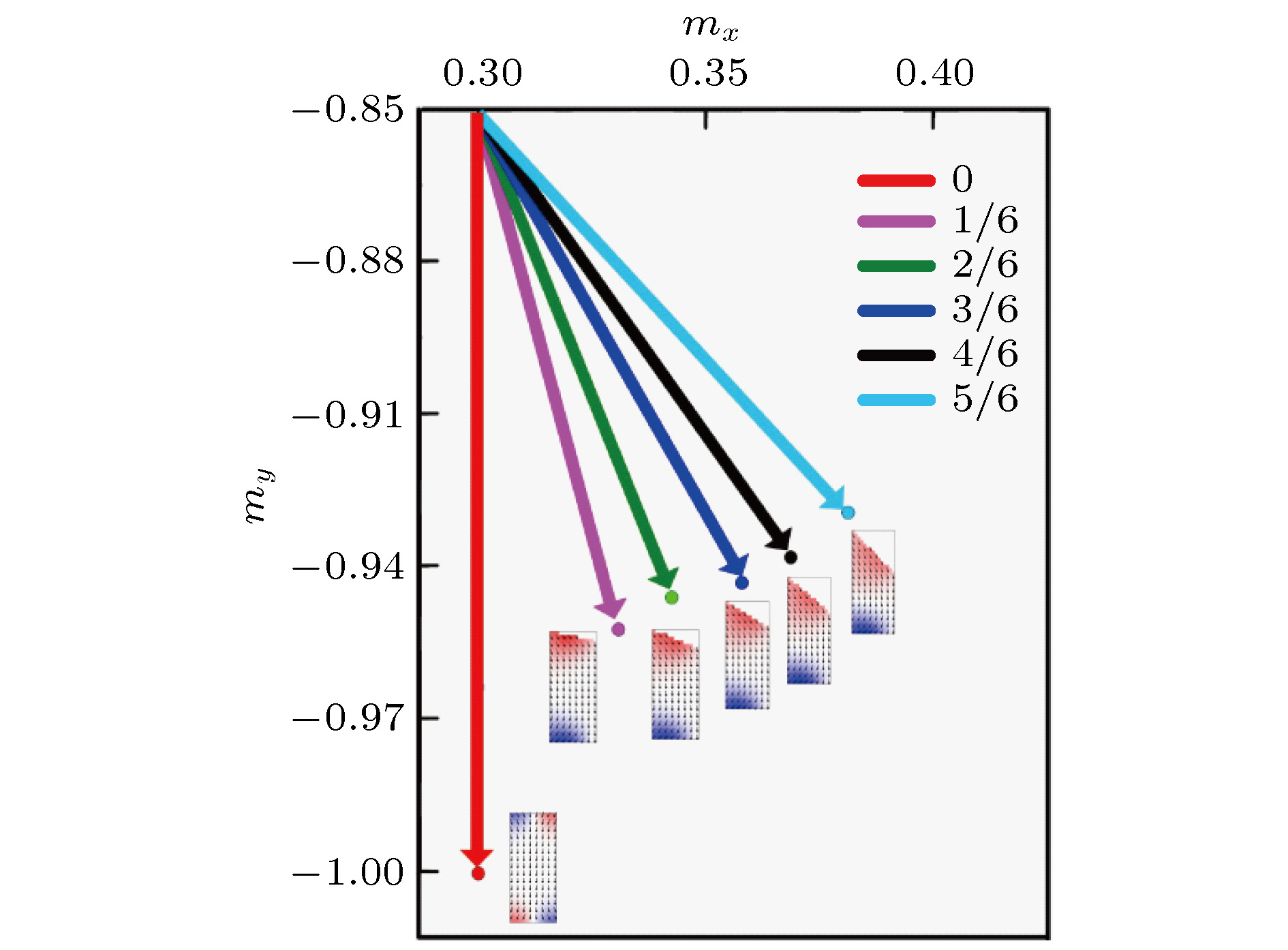 图 2 在室温下, 不同纳磁体(tanθ = 0, 1/6, 2/6, 3/6, 4/6, 5/6)在没有外加磁场激励下的静态自旋方向, 随着缺角的增大非对称条形纳磁体的磁化方向逐渐偏离y轴
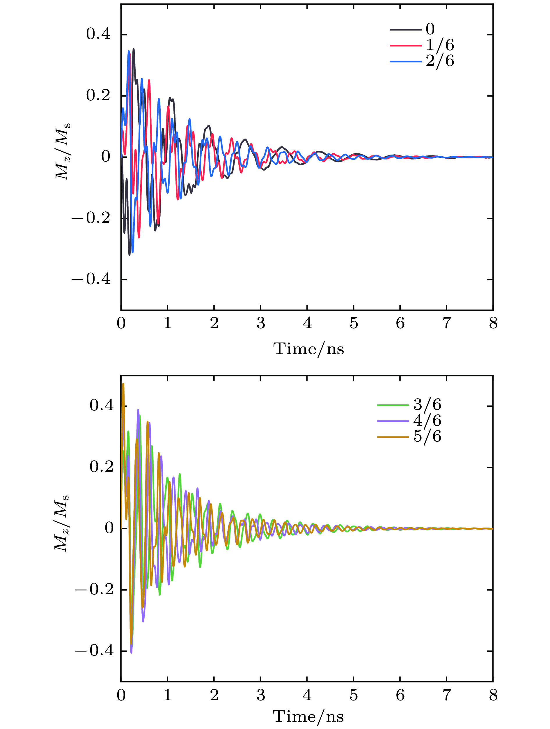 图 3 纳磁体的归一化的磁化分量mz随外加磁场的激励时间的变化
 图 4 不同纳磁体的FMR频率谱和最高吸收峰对应的自旋波模式(tan θ = 0, 1/6, 2/6, 3/6, 4/6, 5/6), 图中的自旋波模式为边缘模式, 红色区域为磁矩的高进动幅值的位置, 蓝色区域为磁矩的低进动幅值的位置
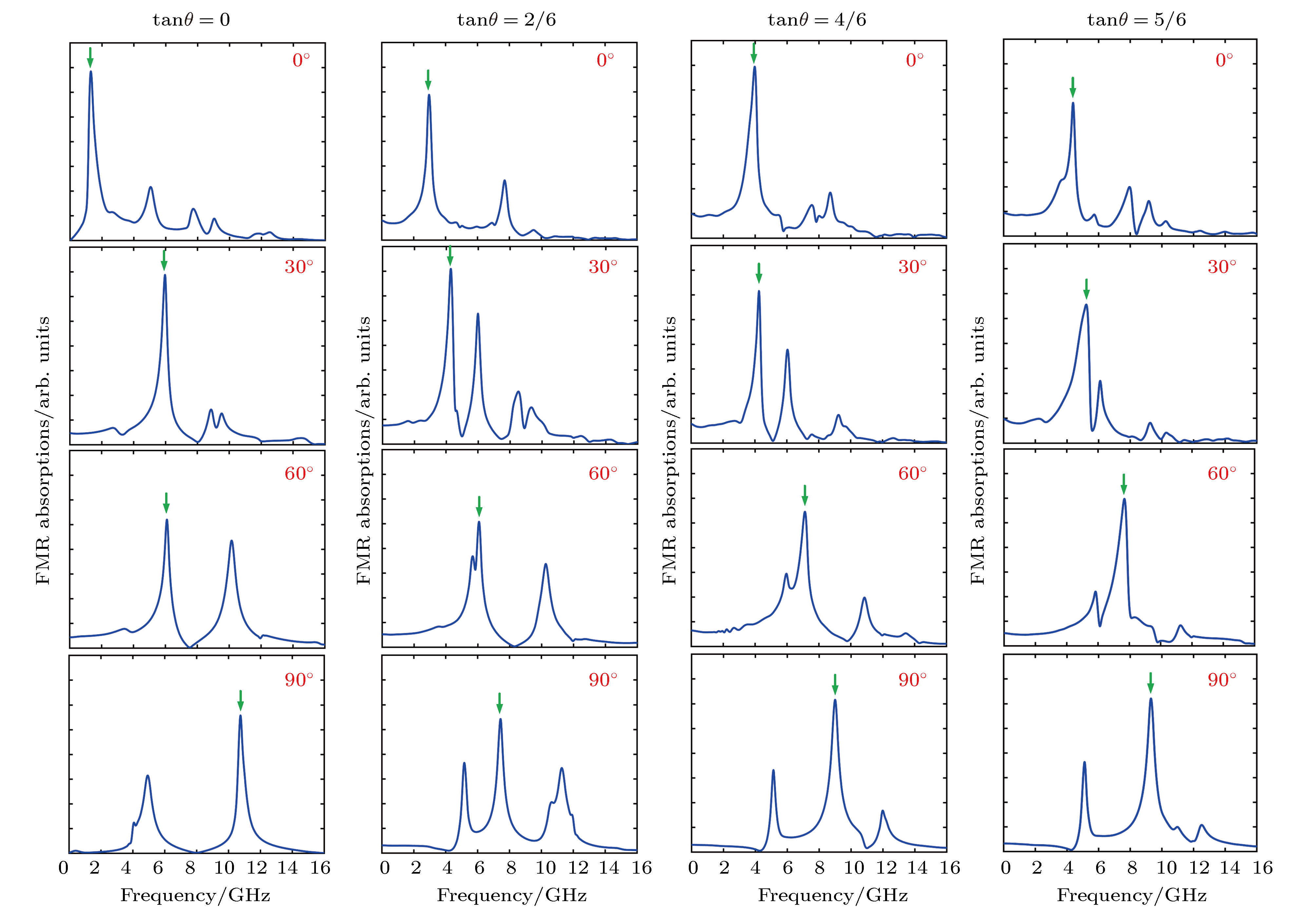 图 5 四种纳磁体(矩形, tanθ = 2/6, 4/6, 5/6的三种非对称条形纳磁体)在不同倾斜角度φ下的铁磁共振频率谱, 绿色箭头标记了最高吸收峰
 图 6 矩形和非对称条形纳磁体(tanθ = 4/6)在不同倾斜角度φ下的自旋波模式. 图的右侧为自旋波模式的进动幅度的色标, 红色区域为磁矩的高进动幅值的位置, 蓝色区域为磁矩的低进动幅值的位置
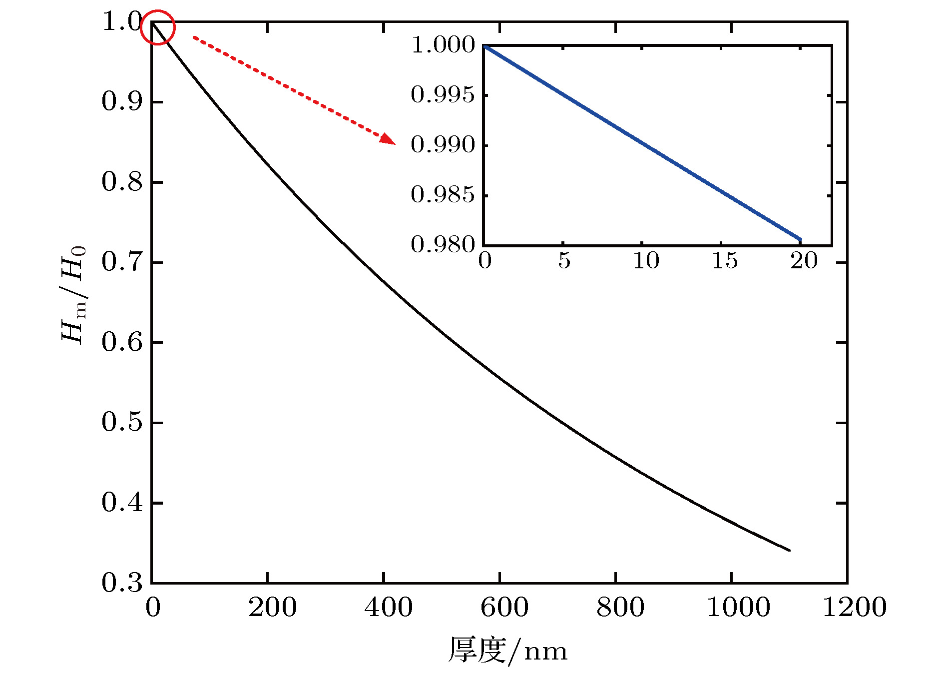 图 7 纳磁体在高频(15 GHz)交变磁场激励下, 外加磁场在内部作用的效果与纳磁体深度的关系, Hm是外加交变磁场作用在材料内部的磁场幅值, H0为交变磁场的幅值