全文HTML
--> --> -->传统产生涡旋光束的方法有计算全息法[14]、螺旋相位板法[15]、空间光调制器法[16]、几何模式转换法[17,18]等. 但是, 受衍射效率的限制计算全息法仅适合低阶涡旋光束的产生; 空间光调制器无法处理高功率光束; 高质量螺旋相位板制作困难; 几何光学模式转换法对光学器件的加工制作要求较高, 转换系统结构复杂且不易控制涡旋的参数. 相比之下, 相干合成涡旋光束在降低系统成本、提高热管理效率和灵活光束控制等方面都具有明显的优势. 基于相干合成技术, Yu等[19]和Xie等[20]已经实现高光束质量特定涡旋光束的相干合成, 且系统架构具有向高功率拓展的优势.
在实际应用中, 对光束质量进行有效评价是非常必要的. 针对不同应用, 人们定义了不同光束质量评价函数, 例如聚焦光斑尺寸、远场发散角、斯特列尔比、衍射极限倍数β因子、光束参数乘积、桶中功率和M2因子等, 也形成了多种检测方法[21-23]. 对于相干合成涡旋光束, 传统分析方法主要利用桶中功率、相关系数等. 但这些评价函数均基于强度分布定义, 只能对强度分布进行评价, 而不能反映合成涡旋光束相位特征.
本文应用螺旋谱分析理论, 对相干合成贝塞尔-高斯(Bessel-Gaussian, BG)涡旋光束进行定量谱分析. 理论推导了相干合成涡旋光束螺旋谱分量的位置和大小. 以目标谱分量纯度为评价函数对合束子光束数量、子光束束腰半径、组束环半径等参数进行了优化, 验证了其作为相干合成涡旋光束评价函数的可行性, 本文对深入理解相干合成涡旋光束的技术本质具有一定参考意义.
2.1.涡旋光束谱分析理论
柱坐标系下, 沿z轴传输的涡旋光束复振幅表达式为

为了定量分析涡旋光束螺旋相位谱特征, 这里引入螺旋谐波分析方法, 设有任意l和


2
2.2.相干合成涡旋光束螺旋谱理论分析
对环形排列的高斯光束阵列加载离散涡旋相位, 相干合成n阶BG涡旋光束. 源平面高斯光束阵列及相位分布如图1(a)和图1(b)所示. 具有离散螺旋相位的高斯光束阵列在自由空间的传播方程为[24]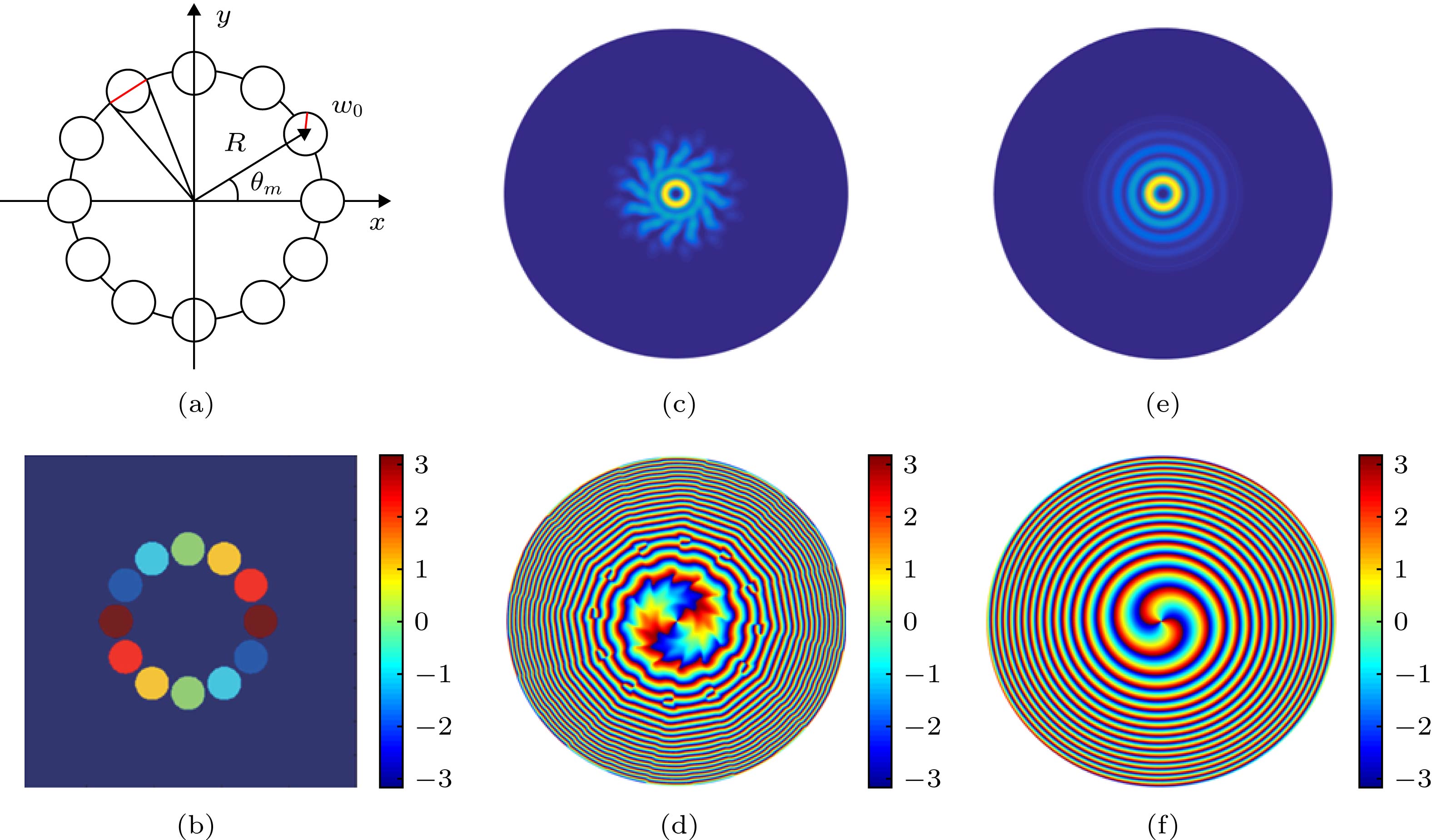 图 1 M = 12, n = 2, R = 1.2 mm, w0 = 0.24 mm时的高斯光束阵列 (a)源平面空间分布; (b)源平面相位分布; (c)传输 2 m后合成涡旋光束强度分布; (d)传输2 m后合成涡旋光束相位分布; (e)标准2阶BG涡旋光束强度分布; (f)标准2阶BG涡旋光束相位分布
Figure1. Gaussian beam array with M = 12, n = 2, R = 1.2 mm, w0 = 0.24 mm: (a) Source plane spatial distribution; (b) source plane phase distribution; (c) light field distribution of synthetic vortex beam after 2 m transmission; (d) phase distribution of synthetic vortex beam after 2 m transmission; (e) light field distribution of standard 2nd order BG vortex beam; (f) phase distribution of standard 2nd order BG vortex beam.


当M = 12, n = 2, R = 1.2 mm, w0 = 0.24 mm时, 子光束阵列及相位分布如图1(a)和图1(b)所示, 根据(6)和(7)式, 计算z = 2 m处与光轴垂直平面内的合成光场强度、相位分布如图1(c)和图1(d)所示, 对比图1(c)与图1(e), 图1(d)与图1(f)可见, (6)和(7)式所示的相干合成涡旋光束是可行的.
结合谱分析理论, 任意z平面处相干合成涡旋光束第l阶螺旋谐波振幅为

为了进一步探究相干合成涡旋光束螺旋谱位置, 可令


2
2.3.相干合成涡旋光束螺旋谱数值分析
以


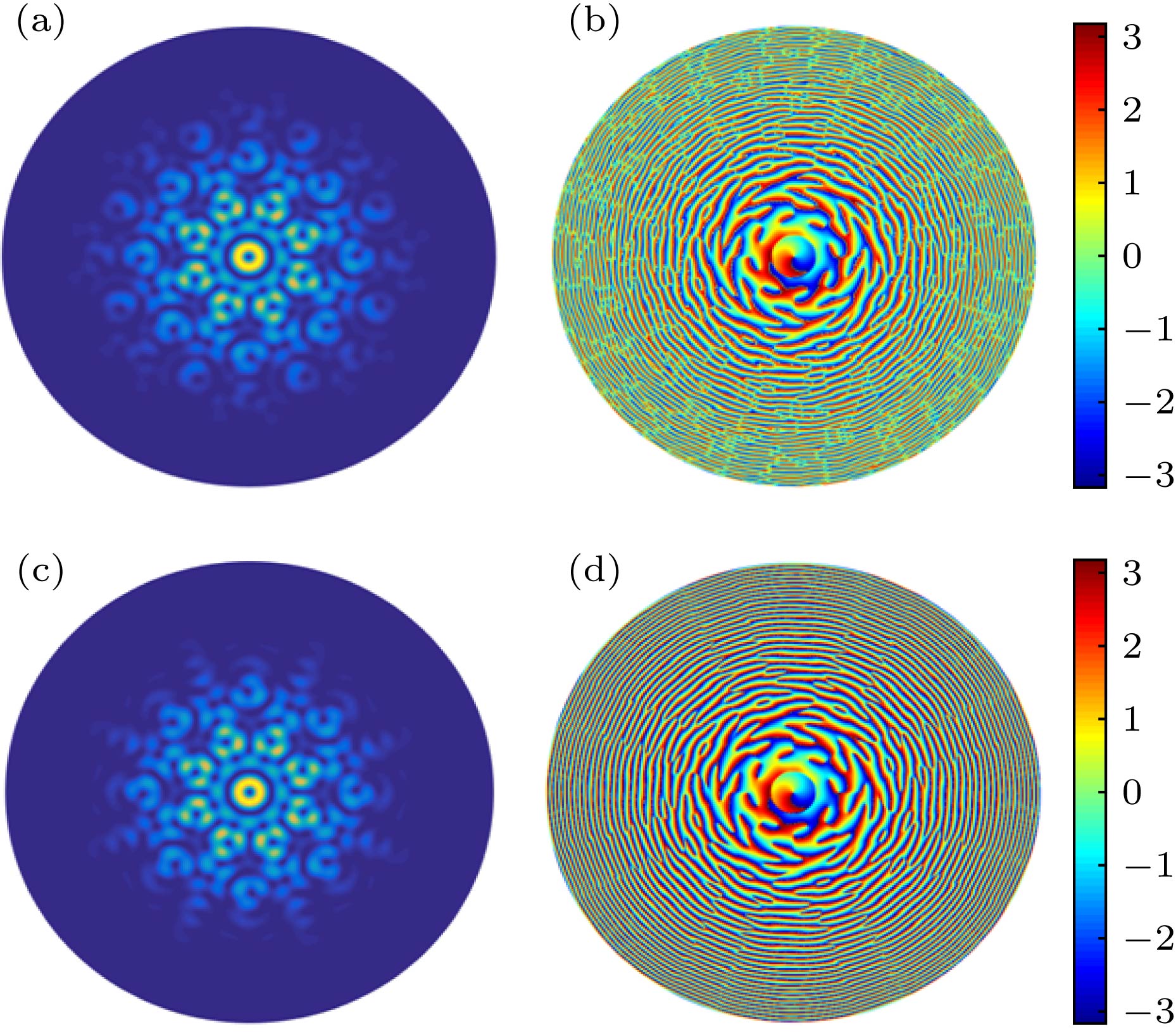 图 2 z = 10 m处相干合成涡旋光束的(a)强度分布和(b)光束相位分布; 螺旋谐波重建的(c)强度分布和(d)相位分布
Figure2. Target plane at z = 10 m: (a) Light field distribution of coherent synthetic vortex beam; (b) phase distribution of coherent synthetic vortex beam; (c) light field distribution of spiral harmonic reconstruction light field; (d) phase distribution of spiral harmonic reconstruction light field.
根据(9)式可计算得到M不同时, 目标合成拓扑荷n为1的相干合成涡旋光束螺旋谱分布及大小, 如图3(a)—(c)所示.
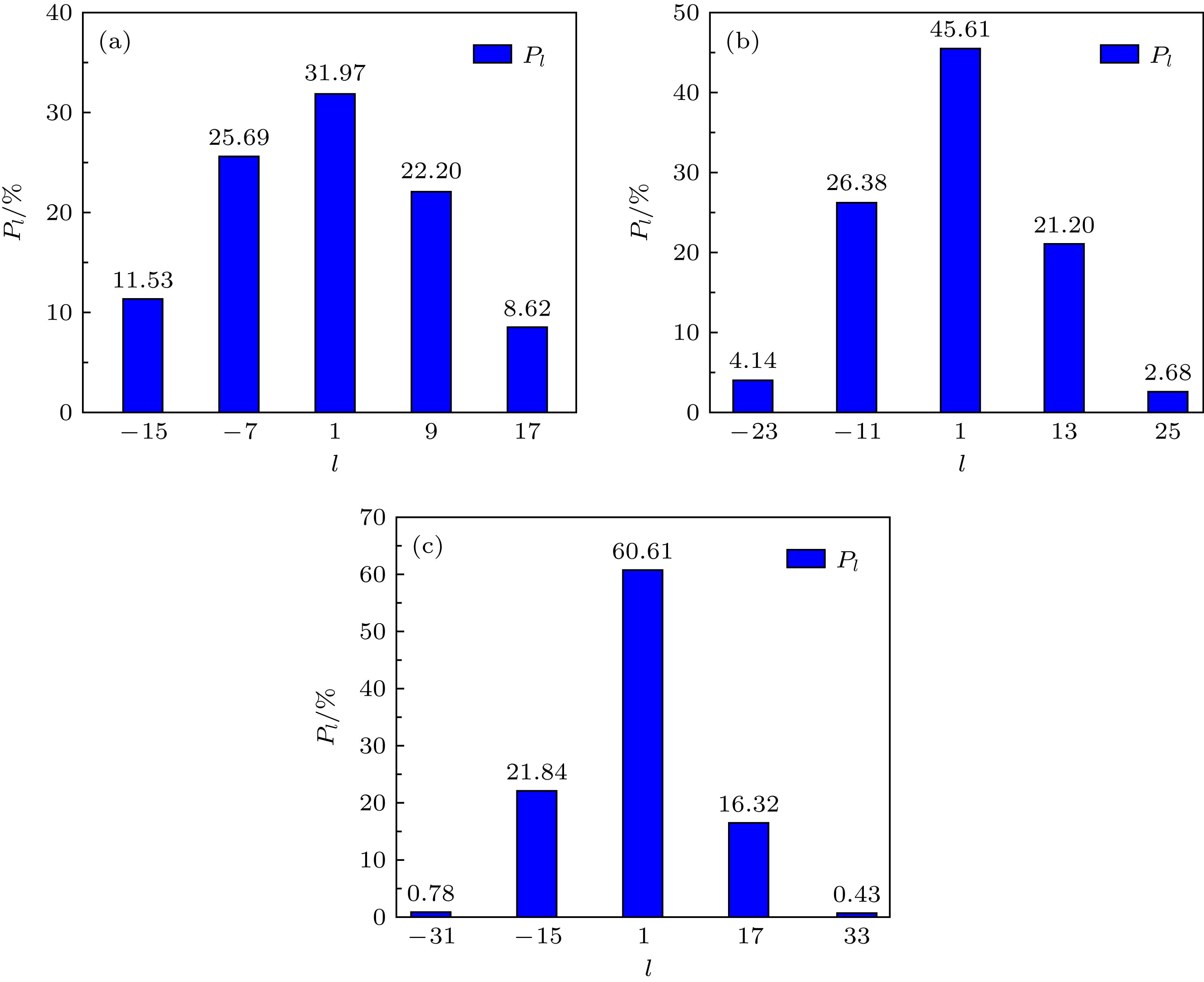 图 3 相干合成涡旋光束螺旋谱分布及大小(其中n = 1, z = 10 m, w0 = 0.2 mm, R = 2.1 mm) (a) M = 8; (b) M = 12; (c) M = 16
Figure3. Coherent synthetic vortex beam spiral spectrum distribution and size (n = 1, z = 10 m, w0 = 0.2 mm, R = 2.1 mm): (a) M = 8; (b) M = 12; (c) M = 16.
图3(a)中, 当M为8时, 拓扑荷为1的螺旋谐波相对功率最高, 为31.97%, 正是相干合成涡旋光束的目标拓扑荷. 根据谱分析理论, 可以预测合成光束非0谱必然出现在


3.1.基于谱分析理论的相干合成涡旋光束参数优化
33.1.1.子光束数量M
根据(7)和(9)式, 计算了n = 1, w0 = 0.2 mm, R = 2.1 mm, λ = 632.8 nm时, M = 8和M = 16两种情况z = 10 m处相干合成BG涡旋光束的强度分布、相位分布以及螺旋谱分布, 分别如图4(a)、图4(c)、图4(e)和图4(b)、图4(d)、图4(f)所示. M = 8和M = 16时拓扑荷n = 1的螺旋谐波相对功率分别为31.97%和60.61%. 可见, 其他参数相同时, M越大合成涡旋光束越接近标准拓扑荷为1的BG涡旋光束. 进一步对比发现: M = 16时合成涡旋光束环外旁瓣明显较少, 主环能量更高, 光束质量更好; 同时合成相位分布中环上交叉条纹更少, 相位分布更加光滑.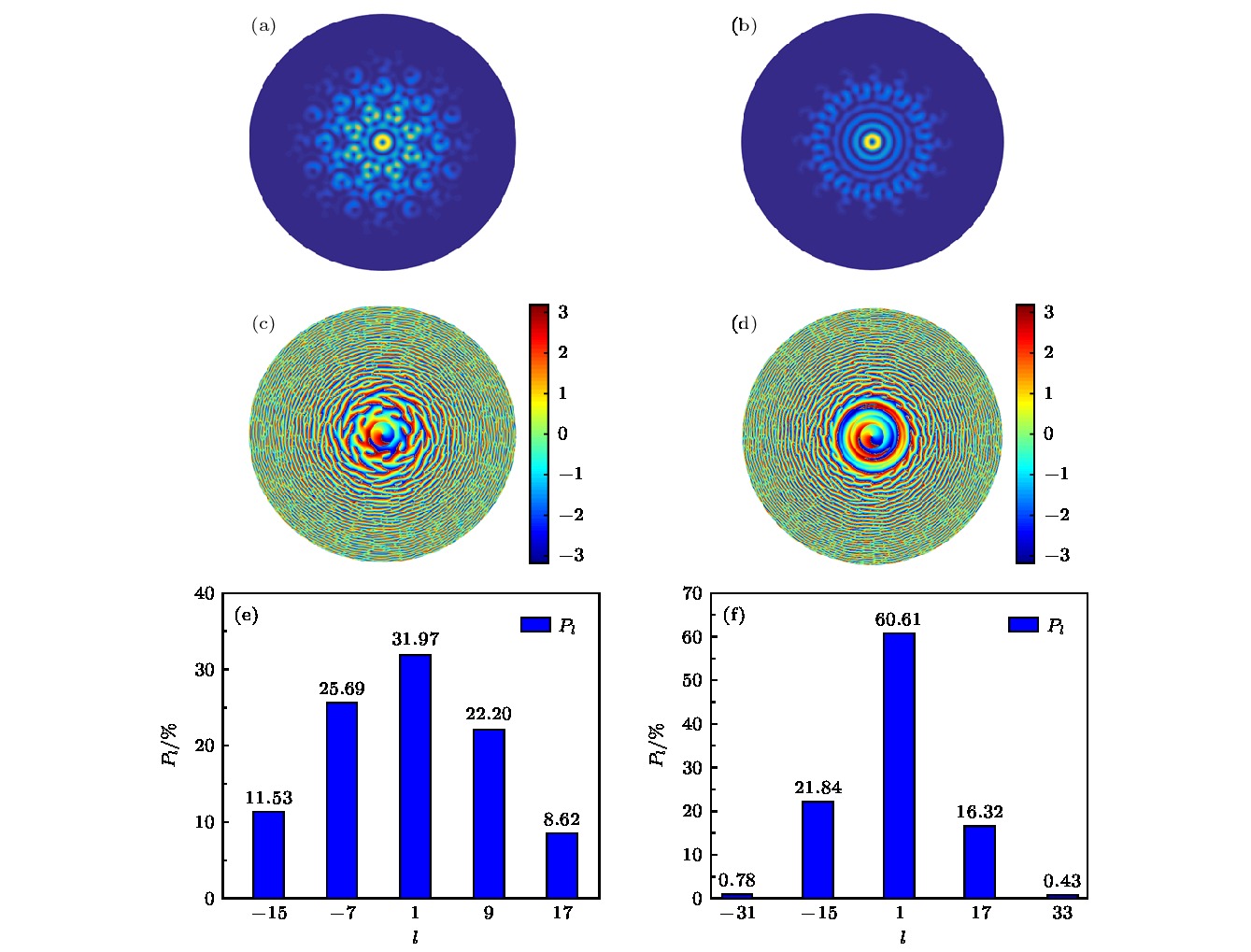 图 4 相干合成BG涡旋光束(n = 1, z = 10 m, w0 = 0.2 mm, R = 2.1 mm) (a) M = 8时强度分布; (b) M = 16时强度分布; (c) M = 8时相位分布; (d) M = 16时相位分布; (e) M = 8时螺旋谱分布; (f) M = 16时螺旋谱分布
Figure4. Coherently synthesized BG vortex beam (n = 1, z = 10 m, w0 = 0.2 mm, R = 2.1 mm): (a) M = 8, light intensity distribution; (b) M =16, light intensity distribution; (c) M = 8, phase distribution; (d) M = 16, phase distribution; (e) M = 8, spiral distribution; (f) M = 16, spiral distribution.
当w0 = 0.2 mm, R = 2.1 mm, z = 10 m 时, 不同目标拓扑荷相干合成BG涡旋光束中心谱纯度Pl随子光束数量M的变化趋势如图5所示. 可见, 随着M不断增大, 非目标螺旋谱分量逐渐减小至0, 目标合成拓扑荷的螺旋谐波纯度不断增加, 趋近100%, 合成光束趋近标准BG涡旋光束.
 图 5 不同阶合成涡旋光束拓扑荷模式纯度Pl随子光束数量M的变化趋势(w0 = 0.2 mm, R = 2.1 mm, z = 10 m)
Figure5. Variation trend of the spectral purity Pl of the different order synthetic vortex beams with the number of sub-beams M (w0 = 0.2 mm, R = 2.1 mm, z = 10 m).
3
3.1.2.源平面束腰半径
根据(7)和(9)式, 计算了n = 1, M = 12, R = 2.1 mm, λ = 632.8 nm时w0 = 0.15 mm和w0 = 0.3 mm两种情况z = 10 m处相干合成BG涡旋光束的强度分布、相位分布以及螺旋谱分布, 分别如图6(a)、图6(c)、图6(e)和图6(b)、图6(d)、图6(f)所示. w0 = 0.15 mm和w0 = 0.3 mm时拓扑荷n = 1的螺旋谐波相对功率分别为35.12%和67.75%. 可见, 其他参数相同时, w0越大合成涡旋光束越接近标准拓扑荷为1的BG涡旋光束. 进一步对比发现: w0 = 0.3 mm时合成涡旋光束环外旁瓣明显较少, 主环能量更高, 光束质量更好; 同时合成相位分布中, 环上交叉条纹更少, 相位分布更加光滑.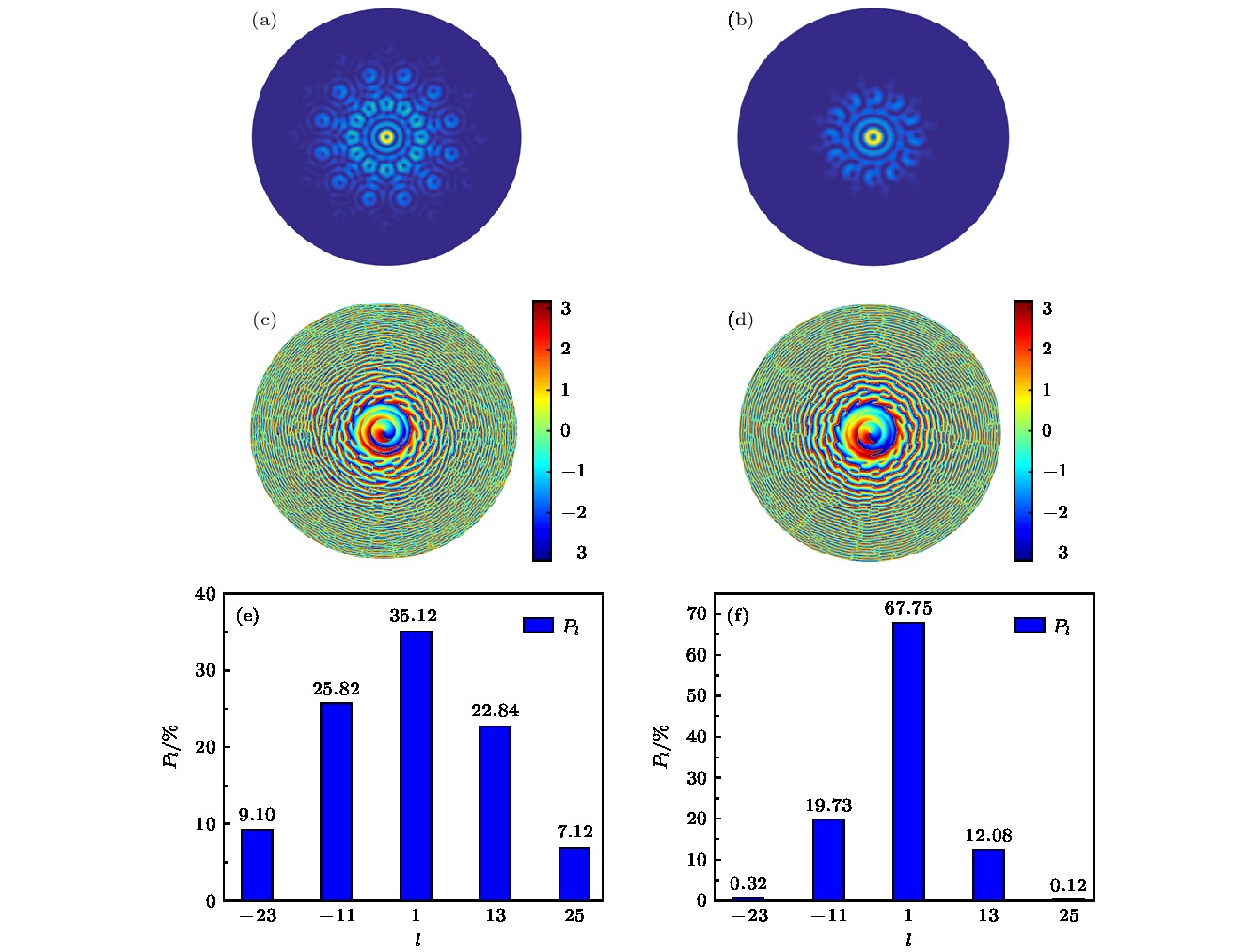 图 6 相干合成BG涡旋光束(n = 1, z = 10 m, M = 12, R = 2.1 mm) (a) w0 = 0.15 mm时强度分布; (b) w0 = 0.3 mm时强度分布; (c) w0 = 0.15 mm时相位分布; (d) w0 = 0.3 mm时相位分布; (e) w0 = 0.15 mm时螺旋谱分布; (f) w0 = 0.3 mm时螺旋谱分布
Figure6. Coherently synthesized BG vortex beam (n = 1, z = 10 m, M = 12, R = 2.1 mm): (a) w0 = 0.15 mm, light intensity distribution; (b) w0 = 0.3 mm, light intensity distribution; (c) w0 = 0.15 mm, phase distribution; (d) w0 = 0.3 mm, phase distribution; (e) w0 = 0.15 mm, spiral distribution; (f) w0 = 0.3 mm, spiral distribution.
当M = 12, R = 2.1 mm, z = 10 m时, 不同目标拓扑荷相干合成BG涡旋光束中心谱纯度Pl随子光束束腰半径w0的变化趋势如图7所示. 可见, 随着w0不断增大, 非目标拓扑荷螺旋谱分量逐渐减小至0, 目标合成拓扑荷的螺旋谐波纯度不断增加, 趋近100%, 合成光束趋近标准BG涡旋光束.
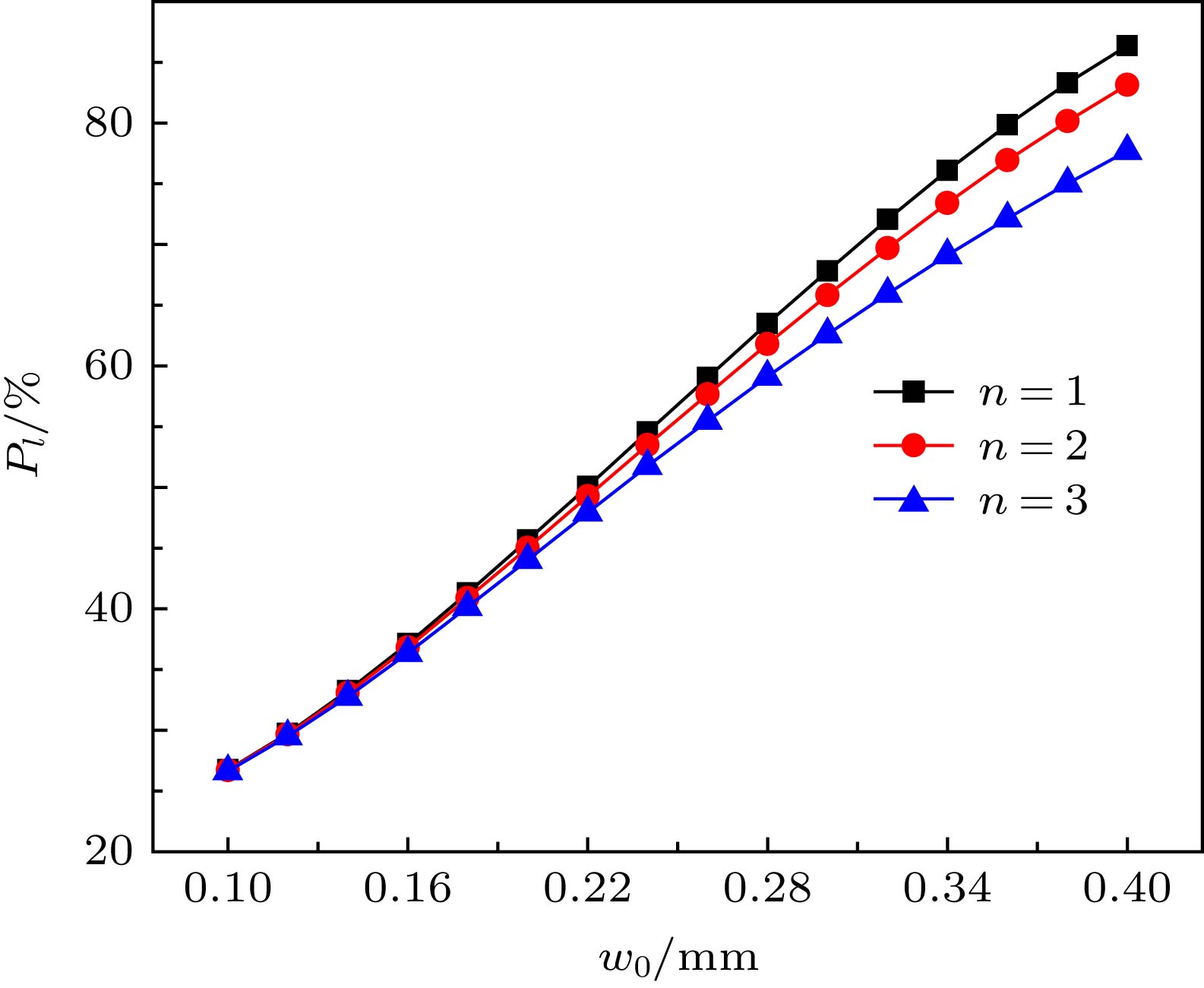 图 7 不同阶合成涡旋光束拓扑荷模式纯度Pl随子光束束腰半径w0的变化(M = 12, R = 2.1 mm, z = 10 m)
Figure7. Variation trend of the spectral purity Pl of the different order synthetic vortex beams with sub beam waist radius w0 (M = 12, R = 2.1 mm, z = 10 m).
3
3.1.3.组束环半径
根据(7)和(9)式, 计算了n = 1, M = 12, w0 = 0.2 mm, λ = 632.8 nm时, R = 1 mm和R = 2.2 mm两种情况z = 10 m处相干合成BG涡旋光束的强度分布、相位分布以及螺旋谱分布, 分别如图8(a)、图8(c)、图8(e)和图8(b)、图8(d)、图8(f)所示. R = 1 mm和R = 2.2 mm时拓扑荷n = 1的螺旋谐波相对功率分别为88.92%和43.62%. 可见, 其他参数相同时, R越小合成涡旋光束越接近标准拓扑荷为1的BG涡旋光束. 进一步对比发现: R = 1 mm时合成涡旋光束环外旁瓣明显较少, 主环能量更高, 光束质量更好; 同时合成相位分布中环上交叉条纹更少, 相位分布更加光滑.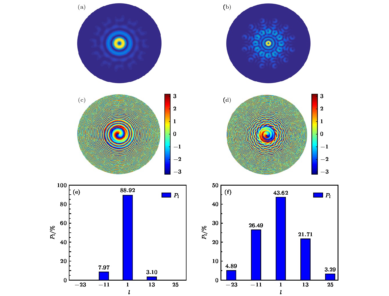 图 8 相干合成BG涡旋光束(n = 1, z = 10 m, M = 12, w0 = 0.2 mm) (a) R = 1 mm时强度分布; (b) R = 2.2 mm时强度分布; (c) R = 1 mm时相位分布; (d) R = 2.2 mm时相位分布; (e) R = 1 mm时螺旋谱分布; (f) R = 2.2 mm时螺旋谱分布
Figure8. Coherently synthesized BG vortex beam (n = 1, z = 10 m, M = 12, w0 = 0.2 mm): (a) R = 1 mm, light intensity distribution; (b) R = 2.2 mm, light intensity distribution; (c) R = 1 mm, phase distribution; (d) R = 2.2 mm, phase distribution; (e) R = 1 mm, spiral distribution; (f) R = 2.2 mm, spiral distribution.
当M = 12, w0 = 0.2 mm, z = 10 m时, 不同目标拓扑荷相干合成BG涡旋光束中心谱纯度Pl随组束环半径R的变化趋势如图9所示. 由图9可见, 随着R不断增大, 非目标拓扑荷螺旋谱分量逐渐增大, 目标合成拓扑荷的螺旋谐波纯度不断减小, 趋近0, 更难相干合成标准BG涡旋光束.
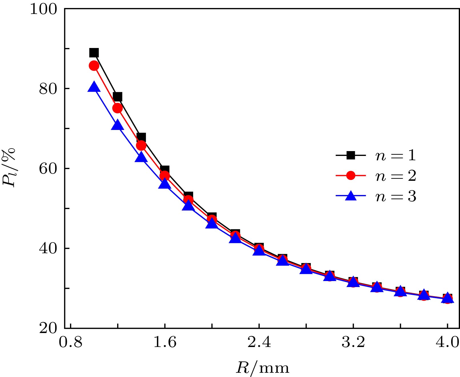 图 9 不同阶合成涡旋光束拓扑荷模式纯度Pl随组束环半径R的变化(M = 12, w0 = 0.2 mm, z = 10 m)
Figure9. Variation trend of the spectral purity Pl of the different order synthetic vortex beams with beam ring radius R (M = 12, w0 = 0.2 mm, z = 10 m).
2
3.2.基于谱分析理论的相干合成涡旋光束质量评价
基于上文对相干合成参数M, w0, R的讨论, 我们发现合成光束螺旋谱分量的位置和大小直观影响了相干合成涡旋光束的光束质量和螺旋相位的合成效果. 目标合成拓扑荷的模式纯度Pl越高, 合成光束的环外旁瓣就会越少, 主环能量更高, 相位分布更光滑, 光束质量更好, 更接近连续涡旋相位的标准BG涡旋光束. 这与采用传统评价函数桶中功率等作为评价函数优化的结论具有一致性. 因此基于谱分析理论, 我们可以通过计算相干合成涡旋光束目标拓扑荷的模式纯度来定量评价涡旋光束质量. 与此同时, 综合M, w0, R三个参数考虑, 可通过占空比Q表示光束阵列圆形排布的紧密程度, 其中

