Fund Project:Project supported by the National Natural Science Foundation of China (Grant No. 11775073) and the Sichuan Provincial Foundation for Program of Science and Technology, China (Grant No. 2019YJ0705).
Received Date:01 May 2019
Accepted Date:07 August 2019
Available Online:01 November 2019
Published Online:05 November 2019
Abstract:For anode layer Hall plasma thruster, the etching of inner magnetic pole is one of the key factors affecting its service life. In order to solve the problem of inner magnetic pole etching in anode layer Hall plasma thruster, the effect of anode magnetic shield on inner magnetic pole etched in anode layer Hall thruster is studied by combining particle simulation PIC with sputtering simulation. The magnetic shielding of anode changes the distribution of magnetic field configuration on the surface of the anode, and improves the magnetic mirror ratio of the magnetic mirror field of the thruster to the magnetic field width of the positive gradient on the central axis. The ratio of the magnetic mirror is 1.4 times that of the original one, and two additional saddle magnetic fields are added on both sides of the original saddle magnetic field region. It not only is conducive to confining electrons and improving the ionization rate of working gas, but also keeps a certain distance between the anode and the high temperature electron region, which provides the reliable reference data for the design of high power Hall plasma thruster. When the discharge voltage is 900 V and the working pressure is 2 × 10⁻² Pa, the simulation results show that after the anode is shielded by the magnetic shield, the energy range of most of the incident ions on the inner magnetic pole is 40–260 eV, which is 100 eV lower than the energy range 40–360 eV in the case without shielding the anode. The probability distribution of particle energy without magnetically shielding the anode between 260 eV and 600 eV is obviously higher than that of ion energy with magnetically shielding the anode. The maximum probability distribution of cosine value of incident angle is extended from a small range near 0.1 (incident angle 84°) to a large range of 0.1–0.45 (incident angle 84°–63°). The magnetic shielding makes the incident ions disperse on the surface of the inner magnetic pole, which is helpful in reducing the etching of inner magnetic pole. The maximum etching rate of inner magnetic pole after the anode has been magnetically shielded is reduced from 16 × 10–10 m/s to 6.1 × 10⁻¹⁰ m/s, which is 2.62 times lower. The comparison of simulation results with experimental results in the case without magnetically shielding the anode shows that they are in good agreement. Keywords:anode layer Hall thruster/ magnetic shield/ incident ion energy/ etching rate
在图1的阳极磁屏蔽结构下, 得到有无阳极层磁屏蔽时的磁场线分布(如图2所示), 通过对比无阳极磁屏蔽的图2(a)和有阳极磁屏蔽的图2(b)可知, 阳极层磁屏蔽时穿过阳极的磁场线明显减少, 阳极表面存在更多的弯曲磁场线, 并且增加了内磁极和阳极之间的径向磁场分量. 由于圆柱形阳极层霍尔推力器内磁场位形是磁镜场分布, 其磁镜比为 图 2 磁场线 (a) 无阳极磁屏蔽; (b) 有阳极磁屏蔽 Figure2. Magnetic field lines: (a) Without anode magnetic shield; (b) with anode magnetic shield.
在推力器的放电电压为900 V, 工作气压为2 × 10⁻² Pa, 无阳极磁屏蔽时得到轰击内磁极上的入射离子数量与总的入射离子比值为0.27, 存在阳极磁屏蔽时的比值降低到0.25. 说明了入射离子束流密度在阳极磁屏蔽下降低了, 由(5)式可知刻蚀速率就会降低. 入射离子的能量越高溅射就越明显, 这点与离子推力器的栅极刻蚀是一样的[21]. 同时得到如图5所示的入射离子的能量概率分布, 可知在无阳极磁屏蔽时入射离子的能量大部分在40—360 eV之间, 通过阳极磁屏蔽以后的入射离子能量在40—260 eV的范围, 由此可知通过阳极磁屏蔽可以使得入射离子的能量整体降低100 eV. 并且在260—600 eV之间无阳极磁屏蔽的粒子能量概率分布要明显高于有阳极磁屏蔽时的离子能量概率分布. 由(5)式可知入射离子的能量${E_0}$降低, 则刻蚀速率就会降低. 所以从入射到内磁极上的离子能量概率分布来看阳极磁屏蔽技术可很大程度上降低磁极的刻蚀速率, 提高磁极的寿命. 图 5 入射离子能量的概率分布 Figure5. Probability distribution of the incident ion energy.
图6是轰击离子入射到内磁极上表面和内表面的入射角余弦值的概率分布. 由图6可知无阳极磁屏蔽时最大概率分布位于入射角余弦值为0.1处(入射角84°), 且随着入射角余弦值的增加概率分布逐渐降低. 而阳极磁屏蔽下的入射角余弦值概率分布主要在0.1—0.45 (入射角84°—63°)之间, 磁屏蔽的存在使得入射离子不沿着特定的一个小范围角度入射, 而是分散在内磁极表面上的各处入射, 这在一定程度上有利于降低内磁极的刻蚀. 图 6 入射角余弦值的概率分布 Figure6. Probability distribution of the cosine of the incident angle.
图7为内磁极上表面的刻蚀速率在径向方向的分布, 沿着径向方向刻蚀速率是逐渐降低的. 无阳极磁屏蔽时, 最大刻蚀速率为16 × 10–10 m/s, 在0.019 m处(靠近内磁极内表面), 之后逐渐降低, 并在径向方向上的外边沿0.0236—0.024 m之间有一个明显的增加. 由图7可知阳极磁屏蔽时的刻蚀速率明显降低, 最大刻蚀速率为6.1 × 10⁻¹⁰ m/s, 内磁极上表面的刻蚀速率比无阳极磁屏蔽时降低了38.2%. 图8为内磁极内表面的刻蚀速率沿着轴向方向的分布情况, 在最底面的刻蚀速率接近于零, 从图5的离子轨迹图也可看出几乎没有离子入射到内磁极内表面的底面. 在轴向–10至–4 mm处的刻蚀速率几乎相同, 之后随着轴向方向的增加刻蚀速率逐渐增加, 在与内磁极上表面的交界处刻蚀速率达到最大值. 此刻蚀速率的分布与实验后的推力器内磁极刻蚀形貌类似(如图9所示). 对比无阳极层磁屏蔽的刻蚀速率走势与图9的150 h后的内磁极内表面和上表面的刻蚀形貌上是一致的. 一方面验证了此仿真计算方法的正确性, 另一方面也证实了阳极磁屏蔽技术不仅在提高引出束流能量方面有很重要的作用[20], 而在降低内磁极的刻蚀方面也起到了很重要的作用. 对于降低内磁极的刻蚀速率, 提高推力器的寿命提供了一个可靠的研究方向. 图 7 内磁极上表面刻蚀速率分布 Figure7. Distribution of etching rate on upper surface of inner magnetic pole.
图 8 内磁极内表面刻蚀速率分布 Figure8. Distribution of etching rate on inner surface of inner magnetic pole.
图 9 实验后的内磁极刻蚀形貌图 Figure9. Photos of the inner magnetic pole after experiment.
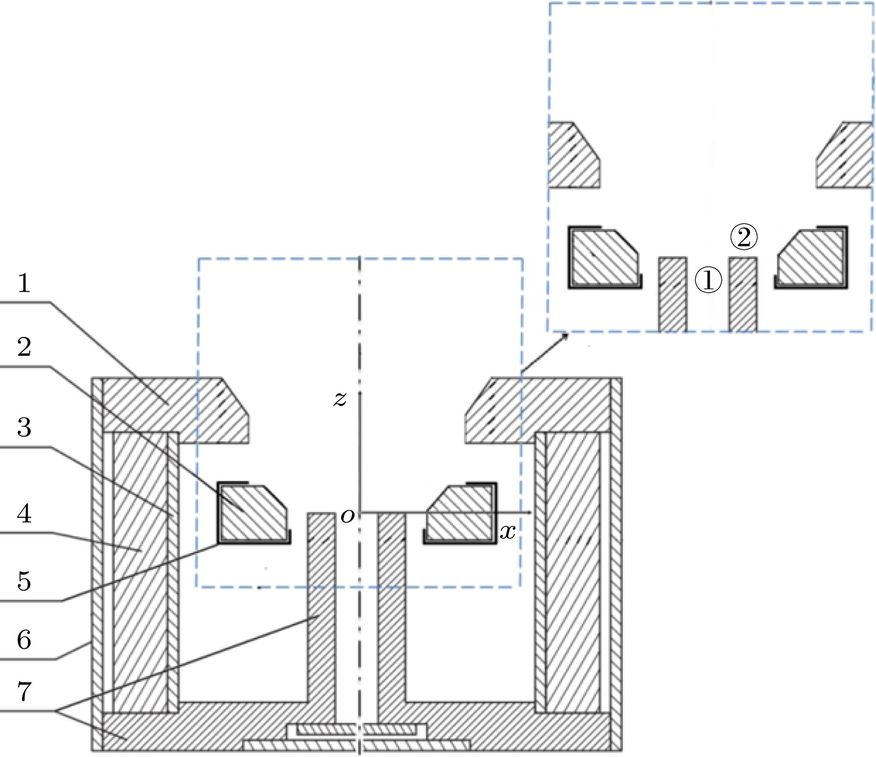 图 1 阳极层霍尔推力器结构示意图(1, 外磁极; 2, 阳极; 3, 内屏蔽筒; 4, 磁钢; 5, 阳极磁屏蔽; 6, 外屏蔽筒; 7, 内磁极)
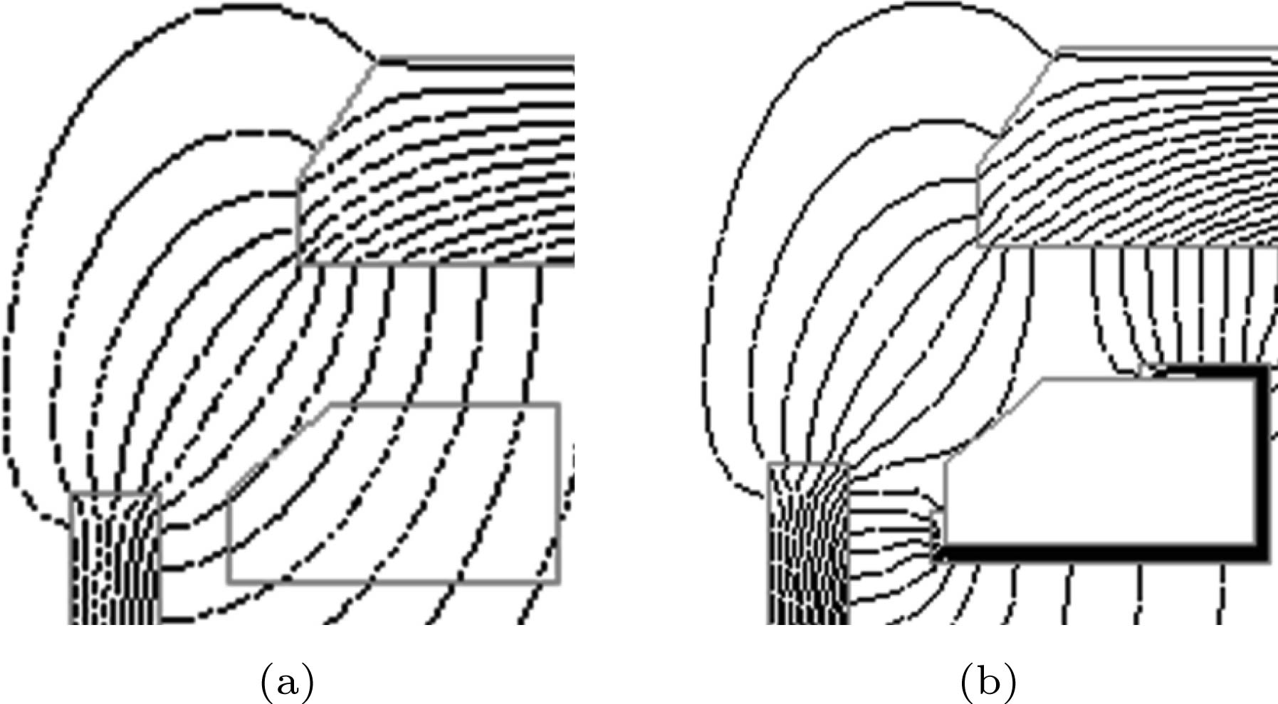 图 2 磁场线 (a) 无阳极磁屏蔽; (b) 有阳极磁屏蔽


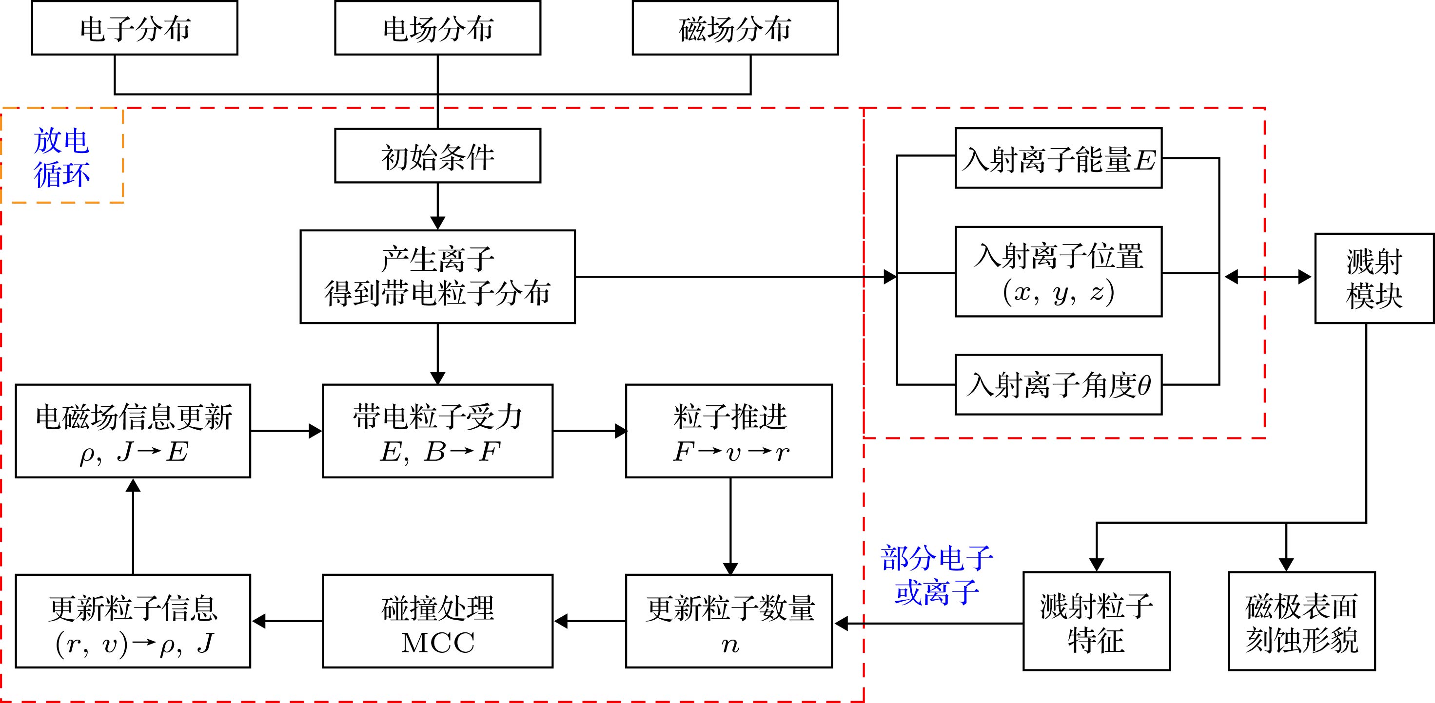 图 3 仿真流程


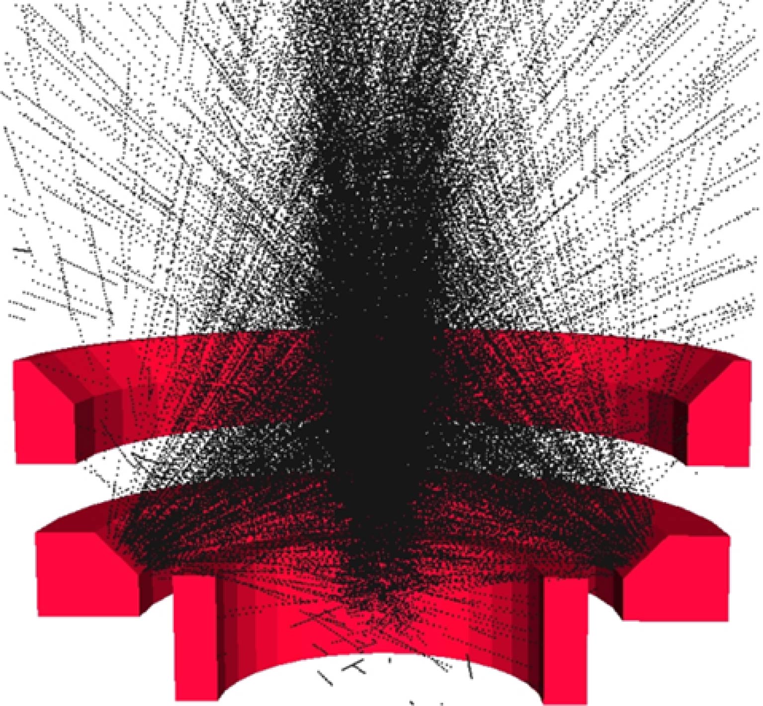 图 4 离子轨迹
 图 5 入射离子能量的概率分布
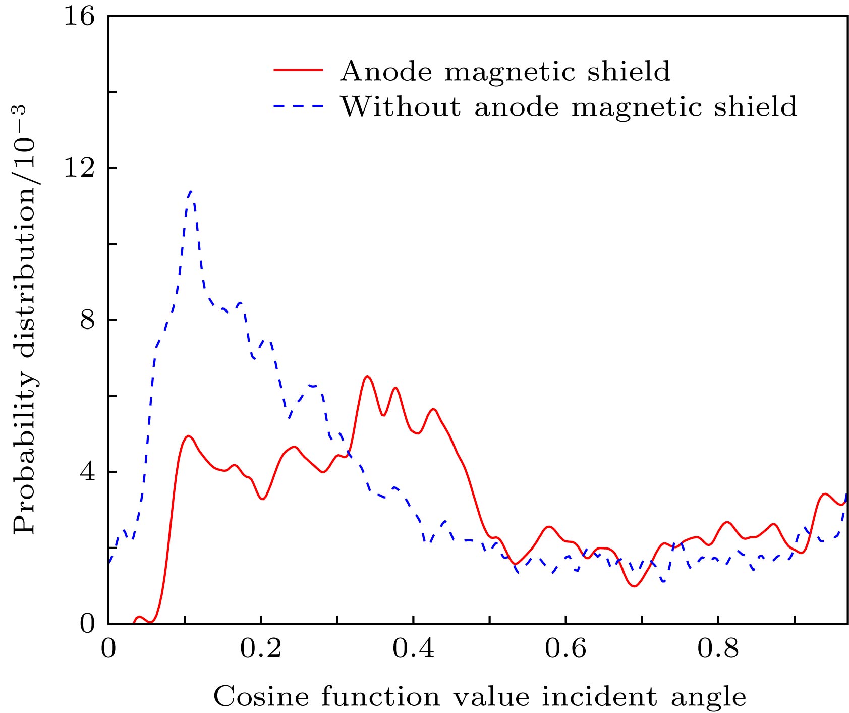 图 6 入射角余弦值的概率分布
 图 7 内磁极上表面刻蚀速率分布
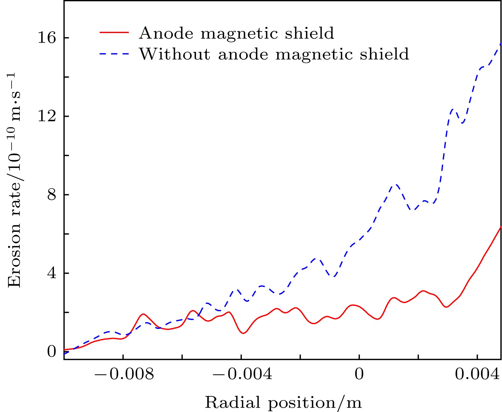 图 8 内磁极内表面刻蚀速率分布
 图 9 实验后的内磁极刻蚀形貌图