全文HTML
--> --> -->高质量的冲击脉冲是利用冲击点火方案实现聚变点火的关键因素. 袁强等[16]通过数值模拟分析了影响冲击脉冲质量的主要参数有冲击脉冲峰值功率、冲击脉冲宽度、冲击脉冲上升沿时间. 这3个关键参数主要会影响冲击点火中实现点火的激光功率阈值和靶增益. 冲击点火所需要的激光峰值功率达到10 TW量级, 但随着功率的增加, 靶增益开始下降, 所以冲击脉冲峰值功率并不是越大越好; 冲击点火所需要的冲击脉冲宽度需要达到100 ps量级, 以提供足够的能量才能实现成功点火, 但宽度越大意味着更多的点火能量输入, 这样又会降低靶增益, 所以冲击脉冲宽度需要结合具体的实验条件进行设计; 冲击脉冲上升沿时间在百皮秒范围时不会影响点火的效果, 但是如果上升沿时间过长就会增强激光等离子体的不稳定性[17,18]. 基于以上分析, 冲击点火脉冲的脉冲宽度、脉冲上升沿时间、峰值功率对比度是影响成功点火的重要参数指标, 因此如何实现高精度可控的冲击脉冲显得尤为重要.
袁强等[19]曾提出利用时域复合技术和空域复合技术来产生冲击点火激光脉冲. 时域复合技术指的是在不同的时段施加不一样的调制, 不同的调制方案达到的效果不同; 空域复合技术指的是将压缩脉冲与冲击脉冲分开调制, 然后再在耦合点处进行时域拼接. 上述工作并没有具体描述如何实现高精度主动可控以及高对比度的冲击脉冲.
本文基于光纤环循环相位调制与光栅对压缩的时间透镜系统[20], 提出一种新的获取冲击脉冲的设计方案并对其进行深度研究. 利用相位调制器对脉冲信号进行非对称频谱展宽(左右两侧均为线性调制, 但调制频率不一样), 然后再利用光栅对对脉冲信号整体进行频域线性啁啾补偿, 实现对脉冲的时域非对称压缩, 从而达到控制冲击脉冲宽度、对比度等参数的目的. 通过建立理论模型和数值模拟, 研究了光纤环时间透镜系统中的相位调制参数(调制函数、调制频率、调制深度、调制圈数等)对频谱信号和光栅对压缩参量对最终输出脉冲波形的影响, 并采用多参量优化方法对各个参数进行了系统优化. 这种对冲击脉冲的脉宽与峰值功率对比度独立高精度可控的研究思路以及具体的参数设计方案, 对产生高质量冲击脉冲具有一定的参考意义.
本文采用了如图1所示的装置, 该装置主要包括三个部分: 第一部分是通过强度调制器将连续光斩波为初始脉冲信号; 第二部分是通过光纤环相位调制系统, 在时域上对脉冲进行循环相位调制, 从而实现光场的频谱展宽, 避免了为实现较宽频谱展宽而采用多个相位调制器级联的弊端; 第三部分是利用光栅对提供一个反常色散, 类似于色散延迟线, 在频域上对信号进行时间调制, 最终实现脉冲压缩.
 图 1 时间透镜装置图(MZ, 马赫-曾德尔调制器; YDFA, 掺镱光纤放大器; AWG, 任意波形发生器; BPF, 带通滤波器; PM, 位相调制器; G1和G2, 光栅1和光栅2)
Figure1. Schematic setup of the time lens concept (MZ, Mach-Zehnder modulator; YDFA, ytterbium-doped fiber amplifier; AWG, arbitrary waveform generator; BPF, band-pass filter; PM, phase modulator; G1 and G2, grating1 and grating2).
如图1所示, 装置第一部分采用了1053 nm波段的单模连续光纤激光器作为种子光, 通过强度调制器(12 GHz的任意波形发生器(AWG)施加调制信号)将连续种子光信号斩波为一定时域宽度和一定频谱宽度的初始超高斯脉冲信号(受强度调制器本身的电学特性影响, 如果需要斩波的脉冲低于10 ps, 需要利用两个强度调制器进行错位削波); 第二部分, 脉冲经过光纤环相位调制系统,光纤环内, AWG施加调制信号精确控制光开关与相位调制器, 放大器的作用主要是补偿激光脉冲经过光开关与相位调制器的功率损耗, 从而能够保证信号持续不断地获得相位调制; 相位调制函数采用分段二次函数, 左右两侧的调制频率不一致并且要保证相位调制函数的时间宽度大于初始斩波输出脉冲的宽度, 这是因为由于光纤的正色散, 脉冲在光纤环内循环数圈之后, 初始脉冲的宽度会增加, 如果相位调制函数的时间宽度小于脉冲宽度, 那么脉冲将不能完全被相位调制函数调制; 由于两侧的调制频率的差异, 脉冲经过相位调制后, 两侧的频谱展宽量不同, 当频谱展宽一定量后, 脉冲将从光纤环内输出; 第三部分, 光纤环输出脉冲经过平行光栅对系统实现压缩, 本系统中构造的平行光栅对系统所产生的色散补偿量主要由平行光栅对整体相对于光信号的入射角和光栅对之间的距离决定. 本文中, 保持激光相对于光栅对的入射角不变, 通过改变平行光栅对之间的距离来控制光栅对所提供的压缩量. 光栅对类似反常色散延迟线, 其作用是对通过的光脉冲施加反常的群速度时延(GVD). 因此, 脉冲经过光栅对系统后, 脉冲被压缩. 在相同的光栅对压缩参数下, 频谱展宽量越大, 脉冲压缩的程度越大.
初始斩波输出的脉冲信号可以表示如下:
其中, n是光纤环的圈数, F是傅里叶变化,

脉冲在光纤环内经过多次循环调制直到其频谱展宽到预先设定好的展宽量, 然后从光开关的另一端口输出进入光栅对压缩系统, 从光纤环输出的激光脉冲可表示为


通常情况下, 二阶色散导致的相位延迟对脉冲的展宽或者压缩起主要作用[22], 光栅对施加的二阶色散相位变化表述如下:
因此, 脉冲经过光栅对压缩之后的信号可表述为
首先利用强度调制器斩波出脉宽大约1.06 ns、频谱宽度大约为0.0045 nm的超高斯脉冲(如图2所示).
 图 2 强度调制器斩波出的脉冲频谱(a)与波形(b)
Figure2. Spectrum (a) and pulseshape (b) of the seed laser after the intensity modulator.
相位调制函数设计图如图3所示, 设计相位调制函数两侧均为二次函数, 保证施加给脉冲的频率啁啾为线性啁啾. 调制深度设定为30. 相位调制函数左右两侧的调制频率自适应输入脉冲的脉宽. 在图2所示的输入脉冲下, 脉冲左侧调制频率fl设定约为1.17 GHz, 右侧调制频率fr设置约为1.3 GHz. 脉冲被相位调制的次数越多, 光谱展宽越大, 但是由于右侧调制频率较左侧调制频率更大, 因此两侧的光谱展宽量有差异.
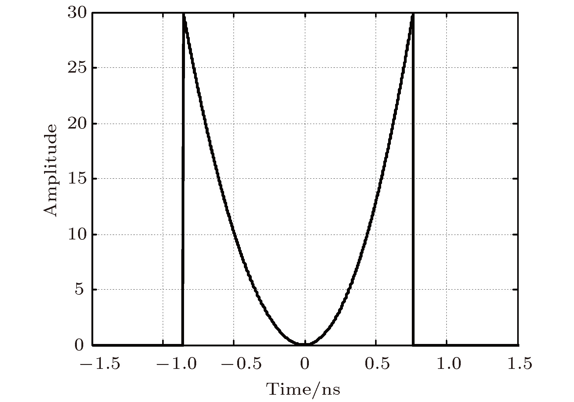 图 3 相位调制函数图
Figure3. Diagram of phase modulation function.
图4是经过相位调制器后的频谱信号与输出脉冲波形. 图4(a)表示输出频谱信号. 随着环绕圈数的增加, 频谱宽度不断增加. 相位调制函数右侧对应的是短波信号, 即蓝移分量, 左侧对应的是长波信号, 即红移分量. 在图3所示的相位调制函数调制下(右侧调制频率大于左侧调制频率), 短波对应的频谱展宽量会大于长波对应的频谱展宽量. 由于能量守恒的原因, 所以图4(a)频谱图中左侧短波信号对应的幅值小于右侧长波对应的幅值. 当环绕圈数达到55圈时, 光谱会发生细微振荡, 这是因为脉冲宽度也在不断增加, 相位调制函数已经不能够完全调制脉冲(脉冲边缘部分没有被调制), 由于光纤的非线性效应(自相位调制)和色散相互作用导致光谱振荡. 图4(b)表示的是输出脉冲信号. 由于光纤的正常色散特性, 脉冲经过光纤环内循环多圈后, 脉冲宽度会展宽. 由于光纤的色散对称地施加于脉冲频谱两侧, 而宽频谱展宽量的脉冲部分获得的色散量更大, 使得脉宽展宽更大, 因此经过光纤色散后输出的脉冲信号的两侧脉宽都展宽, 但是右侧相对展宽更大, 从而也导致右侧的强度幅值小于左侧的强度幅值.
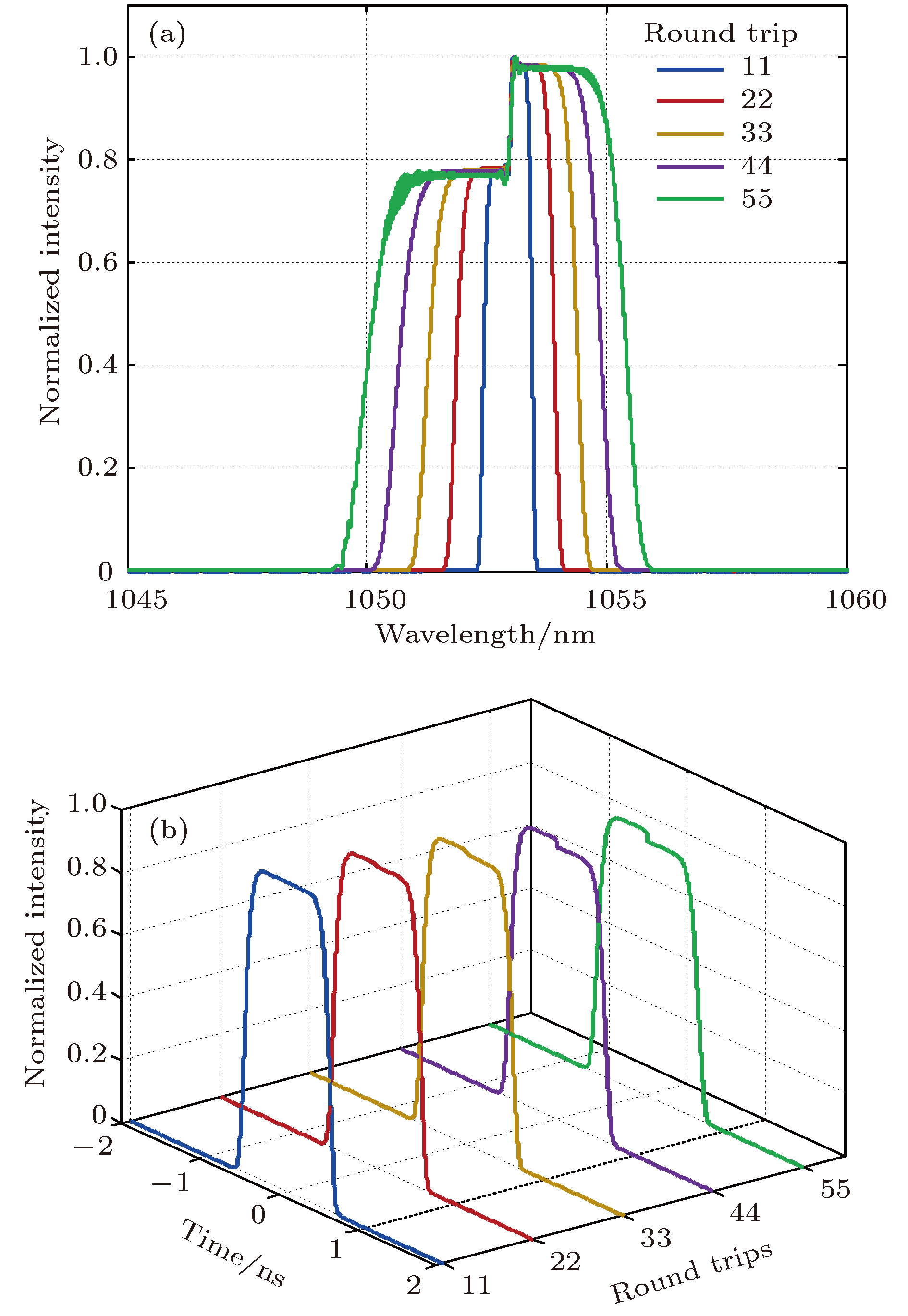 图 4 考虑色散与非线性效应时脉冲信号经过光纤环不同圈数相位调制之后的频谱(a)与脉冲(b) 的演化
Figure4. Evolution of the spectrum (a) and shape (b) of the pulse after different round trips of phase modulation (before compression) when the dispersion and nonlinear effects of fibers are included.
2
3.1.光栅对的间距对冲击脉冲特性的影响
光栅对实际上类似于反常色散延迟线, 即对脉冲信号施加反常色散. 对于拥有正啁啾的脉冲信号经过此光栅对时, 脉冲宽度就会被压缩. 如图4(a)所示, 短波对应的频谱展宽量比长波更大, 因此脉冲在经过光栅对压缩时, 短波更容易被压缩, 所以短波部分对应的强度幅值大于长波部分对应的强度幅值, 于是在时域上便被调制出冲击脉冲形状.对于拥有一定频谱展宽的脉冲再利用光栅对进行压缩时, 该压缩量必然有一个范围, 超过这个范围, 脉冲就会发生分裂和振荡. 脉冲压缩量逐渐增大时, 压缩脉冲与冲击脉冲的宽度都会被压缩且冲击脉冲的峰值功率的对比度也会相应地发生改变. 在本系统中, 控制光栅对角度不变, 通过改变光栅对的间距来调节了光栅对提供的压缩量.
如图5所示, 随着光栅对距离的增大, 光栅对所提供的压缩量越大, 则其压缩输出的脉冲宽度越窄, 同时冲击脉冲峰值功率的对比度越大. 当光栅对的距离为3 m时, 冲击脉冲功率与压缩脉冲的功率之比约为2︰1, 且冲击脉冲的宽度约为100 ps, 符合冲击点火对冲击脉冲宽度的要求. 当光栅对的距离为3.5 m时, 由于光栅对提供的压缩量相对较大造成了过度压缩, 因此冲击脉冲峰值处逐渐发生分裂, 脉冲波形也产生了畸变(如图5插图所示). 因此, 在采用光栅对进行脉冲压缩时, 并不是压缩量越大越好, 需要根据冲击脉冲的特性而设计出相应的压缩参数方案.
 图 5 不同光栅对距离对最终输出脉冲的影响(光纤环环绕圈数设定为55圈, 光栅对角度设定为30°)
Figure5. Final output pulse shape with different grating-pair distance settings (the number of fiber loops is set to 20 turns and the grating pair angle is set to 30 degrees).
2
3.2.输入脉冲波形对冲击脉冲特性的影响
冲击脉冲的上升沿特性对冲击点火效能具有很大的影响, 其中脉冲沿的陡峭度是一个关键参数. 影响冲击脉冲陡峭度的最主要因素是输入脉冲函数的阶数, 阶数越大, 输入脉冲越陡峭, 波形越接近方波, 阶数越小, 输入脉冲越平滑, 波形越接近高斯函数.输入函数的方程可以表示为
模拟过程中, 控制X = 1.7, 脉冲在光纤环中环绕圈数不变(55圈), 控制光栅对参数不变(

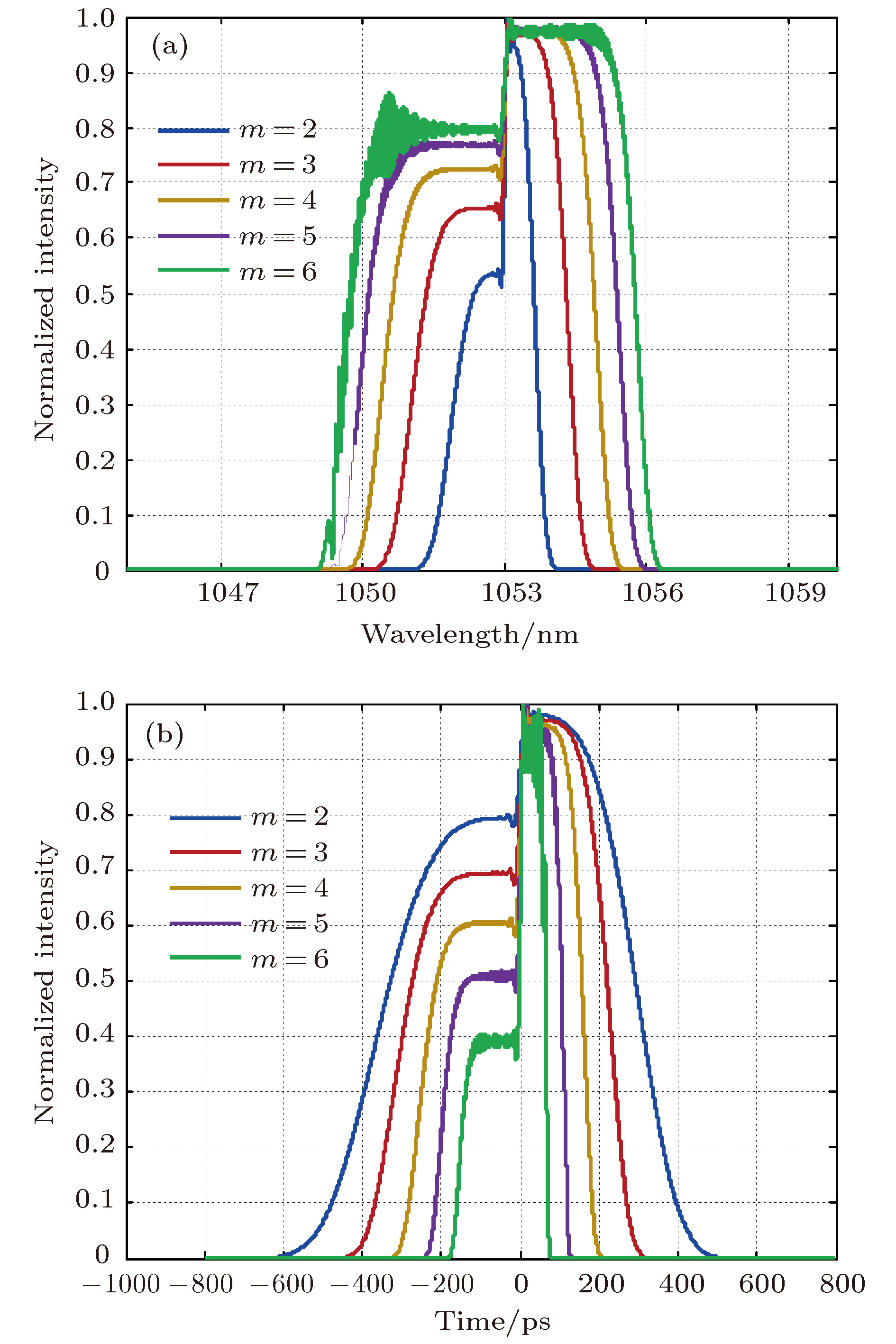 图 6 输入脉冲陡峭度对经过时间透镜系统之后的频谱展宽(a)和脉冲波形(b)的影响
Figure6. Influences of the input pulse shape (different orders of Gaussian function) on the spectrum (a) and pulse shape (b) of the output pulse after being operated by the time lens system.
2
3.3.频谱展宽量对冲击脉冲性能的影响
上述分析表明, 当脉冲获得不同的频谱展宽量时, 必须要计算出光栅对提供的合适压缩量才能产生特定性能指标的冲击脉冲. 影响频谱展宽量的因素主要有单次相位调制的展宽量与相位调制的次数. 影响单次相位调制展宽量的主要因素是相位调制深度与调制频率. 本文研究通过控制光栅对参数不变(

 图 7 压缩量一定时, 频谱展宽量不一样时被压缩输出后的脉冲 (a), (b) 表示调制深度不同的情况下, 频谱展宽与被压缩输出后的脉冲; (c), (d) 表示相位调制次数不同, 频谱展宽与被压缩输出后的脉冲
Figure7. Output pulse after different amount of spectrum broadening when the amount of compression is constant: (a), (b) Broadening spectrum and the output pulse after different modulation depth; (c), (d) the broadening spectrum and output pulse after different round trips.
2
3.4.产生特定冲击脉冲波形的参数设计方案
在具体使用冲击点火方案时, 可能会根据现场实验条件而选择不同指标的冲击脉冲. 基于以上分析, 影响冲击脉冲性能指标的因素有初始斩波函数、相位调制函数、光栅对压缩等参数, 因此通过优化组合设计上述参数达到保证冲击脉冲宽度一定时独立控制冲击脉冲峰值功率对比度、或者保证冲击脉冲峰值功率对比度一定时独立控制冲击脉冲宽度将对灵活控制最终的实验效果具有参考意义.如果光栅对的压缩量不变, 那么经过相位调制之后的频谱展宽中, 仅有在短波(蓝移分量)的频谱展宽量也保持不变的情况下, 冲击脉冲的宽度与冲击脉冲对应的强度幅值才会保持不变, 此时仅需要调节长波(红移分量)的频谱展宽量, 即可单独控制冲击脉冲峰值功率的对比度. 如果冲击脉冲的脉宽发生变化, 则其对应的强度幅值也会发生变化. 在这种情况下, 必须综合调节短波长部分的频谱展宽量、光栅对的压缩量才能保持冲击脉冲峰值功率对比度不变. 因此通过斩波函数、相位调制函数、光栅对压缩量的综合参数设计才能保证冲击脉冲峰值功率对比度一定时独立控制冲击脉冲宽度. 图8(a)中, 斩波函数中X = 1.7, 高斯阶数m = 5, 相位调制函数中调制深度为30, 右侧调制频率fr设置约为1.31 GHz, 光纤环的环绕圈数为55, 控制光栅对参数不变(


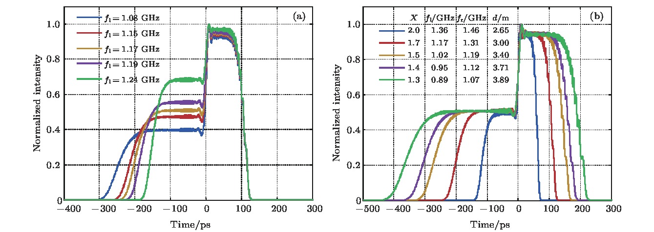 图 8 不同参数设计下最终压缩输出的脉冲 (a) 控制冲击脉冲宽度不变, 改变冲击脉冲峰值功率对比度; (b) 控制冲击脉冲峰值功率之比不变, 改变冲击脉冲宽度
Figure8. Final output pulse under different combined-parameter design: (a) Tuning the ratio of the peak power of the shock pulse and the compress pulse while keeping the shock pulse width unchanged; (b) modifying the shock pulse width while keeping the ratio of the peak power of the shock pulse to the compress pulse unchanged.
