 ,*,?,2)
HYSTERESIS IN VORTEX-INDUCED VIBRATIONS OF A NEAR-WALL CYLINDER1)
Liu Jun*,?, Gao Fuping,*,?,2)通讯作者: 2) 高福平,研究员,主要研究方向:流固土耦合力学 (波流-结构-海床相互作用). E-mail:fpgao@imech.ac.cn
收稿日期:2019-10-22接受日期:2019-11-12网络出版日期:2019-11-18
| 基金资助: |
Received:2019-10-22Accepted:2019-11-12Online:2019-11-18
作者简介 About authors

摘要
柱体涡激振动是典型的流固耦合问题,其响应规律标识码在升速流动和远离壁面条件下获得的. 而自然环境流动通常不断经历升速和降速过程,近壁面柱体的涡激振动可呈现与远离标识码体不同的响应特征. 本研究结合大型波流水槽,设计了具有微结构阻尼的柱体涡激振动装置. 基于量纲分析,开展系列水槽标识码验,通过同步测量柱体涡激振动位移时程和绕流流场变化,研究了升降流速作用下柱体涡激振动触发和停振的临界速度(即上临标识码临界速度)变化规律,探究了近壁面柱体涡激振动迟滞效应. 采用自下向上激光扫射的 PIV 流场测量系统,对比分析了固定柱体标识码振动柱体的绕流特征. 实验观测表明,近壁面柱体涡激振动触发的临界速度呈现随壁面间距比减小而逐渐减小的变化趋势;但标识码速条件下的涡激振动停振所对应的下临界速度却明显小于升速时的涡激振动触发所对应的上临界速度. 采用上临界与下临界约标识码差值可定量表征涡激振动迟滞程度,研究发现该值随着柱体间距比减小呈线性增大趋势. 涡激振动迟滞现象通常伴随振幅阶跃标识码阶跃值则随着间距比减小而非线性减小.
关键词:
Abstract
The vortex-induced vibration (VIV) of a cylinder is a typical fluid-solid coupling problem. Previous investigations on VIV responses were mainly made under increasing-velocity flow and wall-free conditions. Nevertheless, the natural flow always features with alternately increasing or decreasing velocities, so that the VIV response of a near-wall cylinder holds different characteristics from that of a wall-free cylinder. In this study, a VIV device for a cylinder with low structural damping was designed and constructed in conjunction with a flume. Based on dimensional analyses, a series of flume model tests were carried out to investigate the critical velocities for the initiation and the cease of VIV (i.e., the upper critical and lower critical reduced velocities) of a near-wall cylinder under the action of increasing-velocity and decreasing-velocity flows, respectively. To examine wall-proximity effects on the VIV hysteresis, synchronous measurements were made for the time-variation of vibration displacement and the corresponding flow fields around the cylinder. Meanwhile, a specially designed PIV system with bottom-up laser scanning was employed to capture the flow field characteristics. Experimental observations indicate that the critical velocity for the initiation of VIV of a near-wall cylinder decreases with the decrease of gap-to-diameter ratio. The lower-critical reduced velocity for the cease of VIV under decreasing-velocity conditions is however much smaller than the upper-critical value for the initiation of VIV under increasing-velocity conditions. The deviation of the upper-critical reduced velocity from the lower-critical one is used for quantitative characterization of the hysteresis in VIVs, which increases approximately linearly with the decrease of gap-to-diameter ratio. Moreover, it was found that such VIV hysteresis is always accompanied with the jump of vibration amplitude, whose value decreases nonlinearly with the decrease of gap-to-diameter ratio.
Keywords:
PDF (13052KB)元数据多维度评价相关文章导出EndNote|Ris|Bibtex收藏本文
本文引用格式
刘俊, 高福平. 近壁面柱体涡激振动的迟滞效应1). 力学学报[J], 2019, 51(6): 1630-1640 DOI:10.6052/0459-1879-19-293
Liu Jun, Gao Fuping.
引 言
涡激振动是一种典型的流固耦合问题,广泛存在于交通工程、机械工程、海洋工程等领域. 在一定流速下,工程结构后方交替脱标识码旋可诱导结构表面产生压力脉动,使结构受到周期性作用力;而当涡脱落频率与结构固有频率接近时,可诱发结构发生涡激振动[1]. 鉴于流向涡激振动幅值通常较横向幅值小一个量级[2-4],横向涡激振动在工程设计中更受关注. 涡激振动的触发临界速度及幅频响应特性直接影响到结构的疲劳安全性,因而受到了结构设计师和科研人员的广泛关注[5-13].对于海底管道这类柱体结构而言,海床不平顺和局部冲刷均可使其下方悬空而形成管道标识码[14]. 涡激振动的触发临界速度与管道悬跨长度密切相关,通常采用约减速度 $V_{\rm r}$进行表征 ($V_{\rm r}=U/(f_{\rm n}D)$,其中 $U$ 为流速, $f_{\rm n}$ 为柱体在水中的固有频率,$D$ 为柱体直径). DNVGL-RP-F105 设计规范[15]将涡激振动无量纲振幅增大至 $A/D \approx 0.15$ ($A$ 为柱体振动幅值)所对应的约减速度取为涡激振动的触发临界速度 $V_{\rm cr}$. 对于远离壁面的柱体而言,横向涡激振 动通常发生在约减速度 $V_{\rm r} \approx 4.0$ 处. 涡激振动的激发范围主要受管道质量比的影响较大,而最大无量纲振幅则与质量比和阻尼比的组合参数相关[16-20]. 当海底管道与海床边壁之间的间距较小时,壁面剪切流动使得管道绕流流场发生改变,进而影响管道的涡激振动响应. 国内外****已针对近壁面柱体绕流做了大量的实验观测和数值模拟研究[21-26]. 当柱体接近壁面时,柱体表面边界层和壁面边界层可发生相互作用,可导致柱体涡脱落强度受到抑制,涡脱落的抑制程度受到来流雷诺数以及壁面边界层厚度等因素的影响. Lei 等[23]计算表明,当雷诺数${Re}=1.0 \times 10^{3}$时,涡脱落抑制的临界间距比约为0.20. 而随着间距比的减小,斯特劳哈尔数及相应的涡脱落频率均增大 5${\%}$ $\sim $ 10${\%}$ [6,22,27-28]. Raven 等[29]较早开展大型实验研究了海底管道初始间距比对涡激振动触发临界约减速度的影响. Freds${\phi}$e 等[30]随后的研究发现,刚性壁面附近的柱体涡激振动最大振幅及其相应的约减速度均随间距比的减小呈增大趋势. 可见,在工程设计中,柱体涡激振动触发的临界速度的取值需考虑近壁面效应[15].
值得注意的是,上述研究结果大多是在升速流动的条件下获得的,而自然环境流动通常不断经历升速和降速过程. Bishop 和 Hassan[31]以及 Feng[5]曾观察到了升降流速过程中的涡激振动迟滞现象,该现象通常出现在涡激振动幅值阶标识码中,此时柱体振动位移与升力之间的相位差发生跃迁[32]. Williamson 和 Roshko[33]发现,涡激振动幅值阶跃与涡脱落模式转变相关:当系统质量-阻尼参数 $K_{\rm s}$ 较大时(通常 $K_{\rm s} >0.25$, 注:$K_{\rm s}$ 又称“稳定性参数”,其详细说明参见第 1 节),振动幅值随约减速度增大呈现标识码段(即初始阶段和下部阶段),在振幅阶跃前的初始阶段涡脱落是 “2S” 模式,在振幅阶跃到下部阶段时涡脱落突变为“2P”模式. Khalak 和 Williamson[34]进一步研究发现,当系统的质量-阻尼组合参数 $K_{\rm s}$ 较小时 ($K_{\rm s} <0.05$),涡激振动幅值随约减速度的变化则呈现 3 个阶段(包括初始、上部和下部阶段):在初始阶段与上部阶段之间过渡时标识码响应存在迟滞性,而在上部阶段与下部阶段转换时则呈现间歇振动的特征. Singh 和 Mittal[35] 通过数值计算研究了低雷诺数条件下分别单独改变约减速度和单独改变雷诺数时柱体涡激振动的迟滞效标识码回环对应的约减速度区间为 $4.4<V_{\rm r}<4.7$ ($Re =100$),并发现雷诺数对涡激振动迟滞产生一定影响. Prasanth 等[36-38]采用有限单元方法研究了低雷诺数 (${Re}<150$) 条件下的涡激振动迟滞效应,重点关注了质量比标识码比的影响. Wanderley 等[32]通过求解二维雷诺平均N-S方程模拟了升降流速作用下远离壁面柱体的迟滞现象,分析了涡激振动幅值和频标识码力系数与耦合系统吸能的变化趋势. 陈威霖等[39]采用浸入边界法对雷诺数 ${Re}=100$ 条件下的双圆柱流致振动迟滞现象进行了数值模拟研究.
人们对涡激振动迟滞现象已获得了上述初步的基本认识. 涡激振动迟滞通常指振动幅值发生阶跃的约减速度临界值与流动的标识码降速过程相关的物理现象,即涡激振动响应与流动变化路径相关,这表现为升速和降速过程所分别对应的柱体振幅随瞬时标识码化曲线并不重合. 然而已有研究仍局限于定性的实验观测和小雷诺数条件下的数值模拟分析,且主要针对柱体远离壁面的条件. 本文结合大型波流水槽,设计了一套具有微结构阻尼的涡激振动模拟装置,分别采用自下向上激光扫射的PIV流场测量系统标识码位移传感器测量柱体绕流流场和结构振动位移. 基于量纲分析理论和实验观测结果,研究了近壁面柱体涡激振动的触发临界速度及幅频响应规律,着重分析了升降流速过程标识码涡激振动的迟滞效应.
1 量纲分析
近壁面柱体涡激振动的幅频响应,与流体和柱体的性质密切相关并受到壁面的影响. 本文仅研究水中柱体的涡激振动响标识码振动幅值 $A$ 和频率 $f$ 可分别表示为如下主要参量的函数式中,$U$ 为远场来流速度, $\rho $ 为水的质量密度 ($\rho =1.0\times 10^{3 }$kg/m$^{3}$), $\nu $ 为水的运动黏滞系数 (20${^\circ}$C 时,取 $\nu =1.0 \times 10^{ -6}$m$^{2}$/s), $k_{\rm s}$ 为柱体表面粗糙度, $m$为单位长度柱体的质量, $f_{\rm n}$ 和 $\zeta $ 分别为柱体在水中的固有频率和阻尼比, $e$ 为柱体与壁面的初始间距.
根据Buckingham $\Pi $ 定理,选取 $D$, $\rho $ 和 $U$ 等相互独立的3个物理量为基本参量对式 (1a) 和式 (1b) 进行无量纲化,可将振动幅值和频率标识码要影响参量表示为如下无量纲形式
式中,${Re}=UD/\nu $ 为柱体雷诺数;$m^*=4m/\pi \rho D^{2}$ 为结构质量比;系统的质量-阻尼组合参数 $K_{\rm s}=4(m+m_{\rm a}) \zeta / (\pi \rho D^{2})$,其中 $m_{\rm a}$ 为单位长度柱体附加质量 ($m_{\rm a}=C_{\rm A}m_{\rm d}$,对于圆柱而言,$C_{\rm A}=1.0$,$m_{\rm d} = \pi \rho D^{2}/4$);$e/D$ 为柱体与壁面的初始间距比,$\kappa =k_{\rm s}/D$ 为柱体表面的相对粗糙度. 由式 (2a) 可知,当涡激振动触发时,其临界约减速度 $V_{\rm cr}$ 可表达 为如下无量纲参量的函数
涡激振动的迟滞程度,则可采用升速条件下的上临界约减速度与降速条件下的下临界约减速度的差值 $\Delta V_{\rm cr}$ 进行表征(详见 3.1 节). 也就是说,$\Delta V_{\rm cr}$ 越大,涡激振动迟滞程度越高;若 $\Delta V_{\rm cr} \to 0$,则表明迟滞效应可以忽略.
2 实验装置
2.1 实验装置及测试系统
实验是在中国科学院力学研究所的大型流固土耦合波流水槽中进行的. 该水槽长 52.0m,宽 1.0m,高 1.5m, 实验水深 $H =0.5$m. 其造流系统可按预先设定的加载速率自动控制水流速度的升降,最大造流流量为 0.45m$^{3}$/s.在柱体涡激振动迟滞现象模拟中,系统阻尼是一个关键影响参数,需精确控制. 在前期研究中,为实现柱体横向自由振动标识码其沿流向的运动,采用了两对定滑轮进行导向;但由于滑轮和导轨之间存在摩擦和卡顿,从而造成结构阻尼较大且具有不确定性[28]. 为了更好解决上述问题,专门设计了一套具有微结构阻尼的柱体涡激振动模拟装置,布置于水槽中间实验段,如图1 所示. 在实验装置中,利用竖向组合弹簧将柱体结构通过一对刚性导轨悬挂于支撑横梁上;采用一对空气轴承对刚性标识码行竖直导向[19]:气泵产生的高压气体在空气轴承和导轨之间形成气膜,空气轴承与导轨部件之间不发生接触或碰撞. 这样,实验柱体可仅沿垂直于水流方向作竖向振动,并实现微结构阻尼的准确调控.
图1
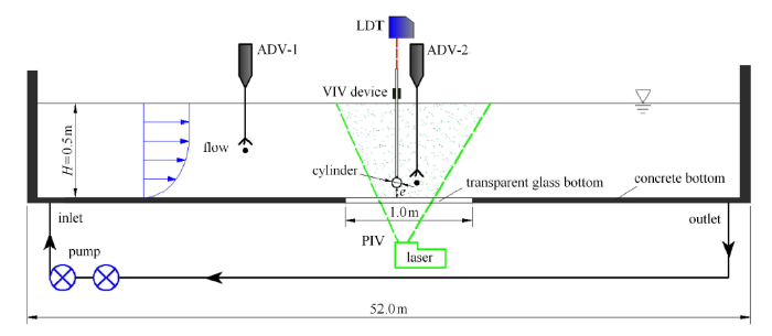 新窗口打开|下载原图ZIP|生成PPT
图1实验布置示意图
Fig.1Schematic diagram of experimental set-up
本实验所采用的柱体结构为直径 $D =0.08$m、长 $L =0.98$m 的有机玻璃管;圆柱体表面光滑,即表面相标识码度 $\kappa \approx 0$. 实验间距比的变化范围 $e/D= 0\sim 1.00$. 柱体内部可以添加配重调节质量比,实验柱体模型的质量比 $m^*=1.85$. 柱体竖向振动位移采用激光位移传感器 (LDT) 进行测量. 水中柱体结构的阻尼比 $\zeta $ 主要包括结构阻尼和流体阻尼两部分. 对于海底管道涡激振动而言,其结构阻尼通常较小,且随着悬跨长度 $L_{\rm s}$ 的增长以 $1/ L_{\rm s}^{2}$ 的比例减小. 流固耦合结构系统的固有频率 $f_{\rm n}$,可通过对水中柱体结构自由振动的位移衰减时程曲线进行频谱分析获得:$f_{\rm n} =0.57$Hz. 系统的阻尼比 $\zeta $ 采用自由衰减法进行测定[1]:$\zeta =\ln( A_{i}/A_{i + n}) /2 \pi n$,其中 $A_{i}$ 和 $A_{i + n}$ 分别为自由衰减振动位 移随时间变化曲线的第 $i$ 个和 $i+n$ 个峰值位移. 本文设计的具有微结构阻尼的柱体涡激振动模拟装置在空气中振动的阻尼比 $\zeta \approx 7.82\times 10^{ - 4}$ (可视为结构阻尼比),在水中的流体阻尼比 $\zeta \approx 1.10\times 10^{ - 2}$. 可见,结构阻尼比相对于流体阻尼比小一个量级以上. 本实验系统的质量-阻尼组合参数 $K_{\rm s}=4( m+m_{\rm a}) \zeta / (\pi \rho D^{2}) \approx 3.14\times 10^{ - 2}$.
实验柱体的绕流流场主要采用激光粒子流场测量系统 (PIV) 进行测量;同时,在柱体下游 1.5 倍管径处布置一支声学多普标识码仪 (ADV) (标号 “ADV-2”,见图1 ) 测量柱体中心高度处的尾流脉动流速. 在水槽中部实验段底部布置有专门设计的一块 1.0m$\times $1.0m 的透光玻璃板,透过该玻璃板采用“自下向上”激光扫射的PIV系统进行流场测量,这可有效避免传统的从水面向下标识码激光布设方式带来的水面反射干扰. 相机位于水槽外侧正对柱体的位置拍摄示踪粒子图像,PIV 在 $x-y$ 平面(沿水流方向为 $x$ 方向,垂直于水流的竖直方向为 $y$ 方向) 的观察区域大小为 400mm$\times $300mm ($5 D\times 3.75 D$). PIV 测量频率为 4.5Hz,每个工况拍摄 300 对粒子图像进行分析. 每个图像对产生大约 5590 (86$\times $65) 对速度矢量 ($u$,$v$),空间分辨率为 4.6mm$\times $4.6mm. 以上所有测量物理量通过实验室自主开发的流固土耦合多物理参数同步测试与实时监控系统进行同步测量.
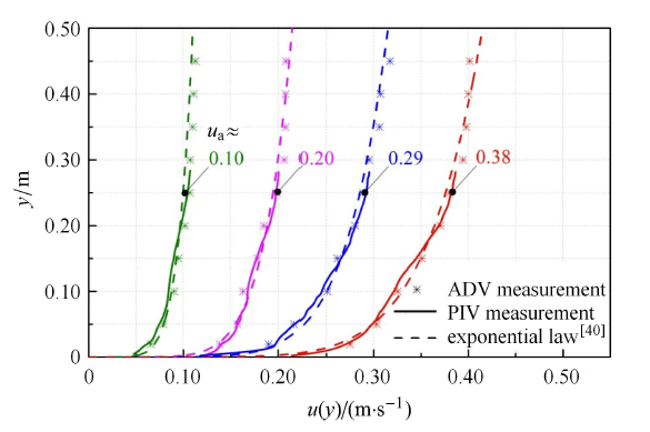
2.2 流动条件
本实验主要探究了升速过程中近壁面柱体涡激振动触发、继而在降速过程中涡激振动停振的临界速度,以及全过程中柱体涡激标识码幅频响应特性. 在实验柱体上游约 3.0m、距离床面 0.25m 处布设了另外一支声学多普勒流速仪(标号 “ADV-1”,见图1 ) 标识码切流动的来流速 度 $U=u |_{y = 0.25{\rm m}} $,记为 $u_{\rm a}$. 在实验过程中,流速先由零匀速升速到最大实验流速约 0.37m/s,随后再对称地匀速降速至零. 实验模拟标识码速度增减变化较小,流动的加速度约为 $\pm 6.67\!\!\times \!\!10^{ - 4 }$m/s$^{2}$,该值远小于柱体涡激振动的加速度,因此流动变化可视为稳态过程. 对壁面剪切流动的流速沿水深标识码分布分别采用 ADV 和 PIV 进行了测量,同时与理论预测结果进行了对比分析. 图2 给出了不同来流速度下 ($u_{\rm a}\!\!\approx\!\! 0.10$m/s,0.20m/s, 0.29m/s 和 0.38m/s),实验段流速沿水深的垂向分布情况. 图中散点“星号”对应ADV测量的不同深度处的剪切速度均值;“实线”对应PIV测量结果;“虚线”则对应指数流速分布预测结果. 根据 Prandtl 流体力学概论(可参见 Oertel[40]),指数流速分布通常满足如下关系:$u(y)=u_{\rm m}(y/H)^{n}$, 式中$u(y)$为距离水槽底面$y$处的流速;$u_{\rm m}$ 为水面处的流速;$n$ 为与来流雷诺数相关的经验参数,其建议取值范围为 $n=1/6\sim 1/10$,本实验中$n$取为 1/7. 可以看出,实验剪切流速沿水深分布基本符合该指数分布预测规律.图2
 新窗口打开|下载原图ZIP|生成PPT
图2不同特征流速下实验段流速的垂向分布
Fig.2Velocity distribution of the test section at typical flow velocities
3 实验结果及分析
3.1 近壁面柱体涡激振动的幅频响应特性
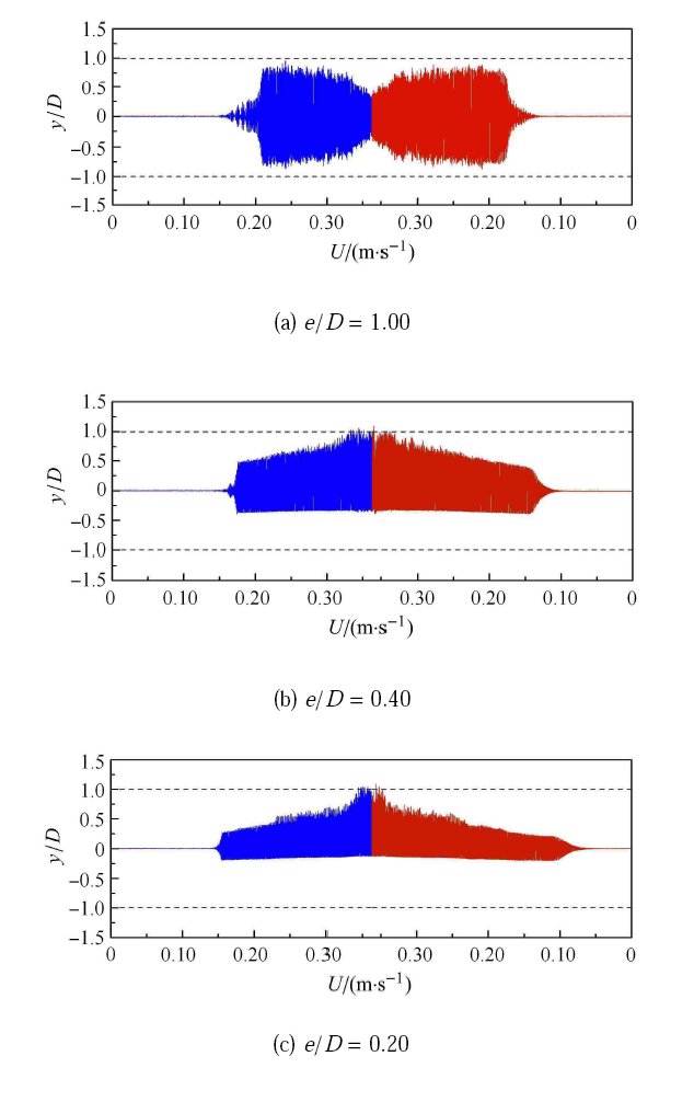
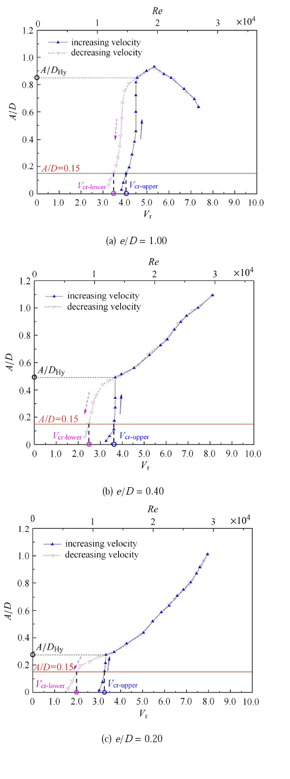
图3 给出了不同间距比 ($e/D =1.00$, 0.40, 0.20) 条件下,升速和降速过程柱体涡激振动的无量纲位移 $y/D$ 随流速变化曲线. 涡激振动触发和停振时的雷诺数 ${Re}$ 在 10$^{4}$ 量级,处于亚临界流动范围. 当 $e/D =1.00$ 时(见图3(a)),柱体涡激振动位移关于平衡位置基本呈对称分布,壁面对柱体振动的影响可以忽略. 尽管流动的升速和降速过程是对称的,但在相同流速下升速和降速过程分别对应的振动位移并不总是相同的. 在降速过程中,维持柱体涡激振动的流速范围明显增大,这说明柱体涡激振动存在迟滞效应. 由图3(b) 和图3(c) 可以看出,随着柱体与壁面间距比的减小,由于下方壁面的影响,振动位移相对于平衡位置不再呈对称分布,标识码下运动时与壁面发生碰撞(即向下的最大振动位移等于柱体与壁面的初始间距),此时柱体相对于平衡位置的向上运动位移更标识码值取为柱体的振幅. 对于间距比较小的情况,同样可发现在降速过程中涡激振动持续的流速范围更大,且随着间距比的减小其趋势愈加明显.图3
 新窗口打开|下载原图ZIP|生成PPT
图3升降流速过程柱体涡激振动位移随流速变化
Fig.3Variations of cylinder displacement with velocity both showing increasing and decreasing velocities ($D =0.08$m,$m^*=1.85$,$f_{\rm n} =0.57$Hz, $\zeta = 1.10\times 10^{ - 2}$, $K_{\rm s}=3.14\times 10^{ - 2}$,$0 \leqslant Re<4\times 10^{4}$)
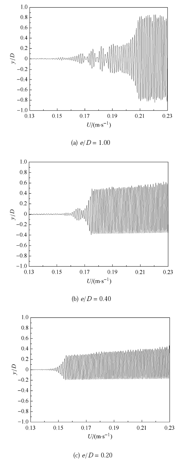
为了清晰展示涡激振动触发的动态响应过程,图4 给出了升速过程中柱体涡激振动触发前后的无量纲位移随流速的变化曲线. 由图4(a) 可以看出,对于远离壁面情况 ($e/D =1.00$),当流速较小时,柱体保持静止状态,未发生振动;随着流速的增大,一定流速范围内,柱体在平衡位置附近作标识码歇振动;随着流速逐步增大到某特定值,柱体振动幅值在短时间内急剧增大,发生振幅阶跃;当流速继续增大,柱体振标识码最大值随后逐渐减小(见图3(a)).对比图4(a) $\sim$图4(c) 可发现,随着间距比的减小,涡激振动触发前的间歇振动持续范围减少直至消失,振幅增长更趋平滑,涡激振标识码的速度也逐渐减小. 这说明,尽管间距比较小时壁面对柱体绕流涡脱落强度有削弱,但对于微结构阻尼系统而言,柱体涡激振动难以被抑制,反而更容易触发.
图4
 新窗口打开|下载原图ZIP|生成PPT
图4升速阶段涡激振动触发前后柱体位移随流速变化
Fig.4Variations of cylinder displacement with velocity before and after the onset of vortex-induced vibration in increasing velocity stage ($D =0.08$m,$m^*=1.85$,$f_{\rm n} =0.57$Hz, $\zeta =1.10\times 10^{ - 2}$,$K_{\rm s}=3.14\times 10^{ - 2}$,$Re =O(10^{4})$)
将图3 给出的上述实验结果进行无量纲化处理,可分析获得升速和降速整个过程中柱体无量纲振幅随着约减速度标识码曲线(见图5 ). 参考 DNVGL-RP-F105 规范[15],本文将升速和降速过程中的无量纲振幅 $A/D =0.15$时对应的约减速度值分别确定为涡激振动触发和停振的临界约减速度. 将上述两个临界速度分别定义为涡激振动触发的上临界约减速度 ($V_{\rm cr- upper}$) 以及涡激振动停振的下临界约减速度 ($V_{\rm cr - lower}$). 由图5(a) 可以看出,在升速和降速过程中,涡激振动幅值响应曲线并不完全重合:降速过程引起涡激振动停振所对应的标识码速度明显小于升速过程诱导涡激振动触发所对应的上临界速度. 可见,升降流速作用下的涡激振动响应具有迟滞效应. 迟滞效应通常发生在涡激振动幅值阶跃附近,发生迟滞时所对应的最大振幅用 $A/D_{\rm Hy}$ 表示. 从图5(b) 和图5(c) 同样可以看出,在近壁面条件下(如 $e/D =0.40$, 0.20),涡激振动的下临界约减速度也明显小于上临界速度,迟滞效应也发生在涡激振动振幅阶跃处;但迟滞时所对应标识码振幅 $A/D_{\rm Hy}$ 则随 $e/D$ 呈减小趋势.
图5
 新窗口打开|下载原图ZIP|生成PPT
图5升降流速过程柱体振动幅值随约减速度变化
Fig.5Variations of vibration amplitude with reduced velocity both showing increasing and decreasing velocities ($D =0.08$m,$m^*=1.85$,$f_{\rm n} =0.57$Hz, $\zeta = 1.10 \times 10^{ - 2}$,$K_{\rm s} =3.14 \times 10^{ - 2}$,$Re =O(10^{4})$)
图6 给出了升降流速过程中无量纲振动频率随约减速度的变化曲线;图中也给出了斯特劳哈尔定律线 ($f/f_{\rm n} = 0.2 V_{\rm r} $) 以 及系统的固有频率线 ($f /f_{\rm n} = 1.0$) 以作参考. 在不同间距比条件下,升速过程中的柱体涡激振动频率均随约减速度增大而增大. 对于远离壁 面的柱体而言(如 $e/D =1.0$),当约减速度较小时,振动频率和涡脱落频率遵循斯特劳哈尔定律;随着流速的增大,涡激振动幅值标识码跃时,振动频率也发生跃迁,即由小于固有频率的值跃迁至大于固有频率的值,涡脱落频率被柱体振动频率所控制而发生锁频,标识码循斯特劳哈尔定律. 随着流速的进一步增大 ($V_{\rm r} > 5.5$),振动频率虽仍成增大趋势,但振动频率则介于斯特劳哈尔频率和固有频率之间. 在降速过程中,在较大约减速度时标识码频率和升速过程基本保持一致;然而当约减速度较小时(接近停振时),振动频率并未发生明显跃迁现象,而仍按原趋势逐渐减小标识码维持在略低于固有频率值附近.可见,分别在升速和降速过程中,涡激振动触发和趋于停振 ($3.0 < V_{\rm r} <4.5$) 所对应的振动频率响应也存在显著差异:在相同约减速度下,振动触发时的频率明显低于趋于停振标识码率(见图6(a)). 而对于近壁面的柱体而言(见图6(b)、图6(c)),其频率变化趋势与远离壁面的情况类似(见图6(a));但在相同约减速度下,随着标识码的减小,振动频率有增大趋势.
图6
 新窗口打开|下载原图ZIP|生成PPT
图6升降流速过程中柱体振动频率随约减速度的变化
Fig.6Variations of vibration frequency with reduced velocity both showing increasing and decreasing velocities($D =0.08$m,$m^*=1.85$,$f_{\rm n} =0.57$Hz, $\zeta = 1.10 \times 10^{ - 2}$,$K_{\rm s}=3.14\times 10^{ - 2}$,${Re}=O(10^{4})$)
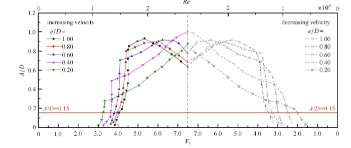
图7 对比了不同$e$/$D$条件下柱体涡激振动无量纲振幅随着约减速度的变化趋势. 图7左侧为升速过程的变化曲线;右 侧为降速过程的变化曲线. 可以看出,在本文所研究的间距比范围内 ($0.2 \leqslant e/D \leqslant 1.0$),涡激振动触发的临界约减速度随着间距比的减小而减小,这表明涡激振动触发更加容易. 然而,涡激振动触发过程中的振幅阶跃值却也随着间距比的减小而减小,且最大振幅对应的约减速度随着间距比的减小而增大. 对比图7 的升速和降速过程可以发现,降速过程中的振幅随着约减速度的变化趋势和升速过程基本一致,但降速引起涡激标识码振所对应的临界约减速度小于升速引起涡激振动触发的临界值.
图7
 新窗口打开|下载原图ZIP|生成PPT
图7升降流速过程振动幅值随约减速度的变化
Fig.7Variations of vibration amplitude with reduced velocity both showing increasing and decreasing velocities ($D =0.08$m,$m^*=1.85$,$f_{\rm n} =0.57$Hz, $\zeta = 1.10\times 10^{ - 2}$,$K_{\rm s}=3.14\times 10^{ - 2}$,$Re =O(10^{4})$)
图8 对比了不同 $e/D$ 条件下柱体涡激振动无量纲振动频率随约减速度的变化趋势,图8(a) 和图8(b) 分别对应标识码降速情况. 由图8(a) 可发现,在升速过程中,涡激振动频率随约减速度增大而增大;在给定约减速度时,振动频率则随着间距比的减小而增大. 对于不同间距比条件,涡激振动触发阶段振动幅值发生阶跃(见图5 )的同时,振动频率也发生跃迁(见图8(a));频率跃标识码值则随着间距比的减小而增大. 如前所述,与升速过程不同,降速过程中的涡激振动趋于停振时的振动频率未发生明显跃迁,而是随约减速度的减小逐渐趋于标识码系统固有频率的稳定值.
图8
 新窗口打开|下载原图ZIP|生成PPT
图8升降流速过程振动频率随约减速度的变化
Fig.8Variations of vibration frequency with reduced velocity both showing increasing and decreasing velocities ($D =0.08$m,$m^*=1.85$,$f_{\rm n} =0.57$Hz, $\zeta =1.10\times 10^{ - 2}$,$K_{\rm s}=3.14\times 10^{ - 2}$,${Re}=O(10^{4})$)
3.2 振动柱体与固定柱体绕流流场对比
当柱体涡激振动触发后,尾涡脱落和固定柱体会有显著不同. 为了定量研究柱体振动对尾涡脱落强度的影标识码文采用旋流强度值 $\varOmega $ 来定量表征旋涡[41],其能够很好地区分旋涡和剪切流动. 定义速度梯度张量 $\nabla {\pmb u}$ 具有复特征值的区域为旋涡,对于二维流动,速度梯度张量的特征多项式为当 $\varDelta <0$ 时,$\nabla {\pmb u}$ 有一对共轭复根,代表粒子做旋转运动,即有旋涡. 旋流强度值 $\varOmega $ 定义为
单位为 s$^{ - 2}$.
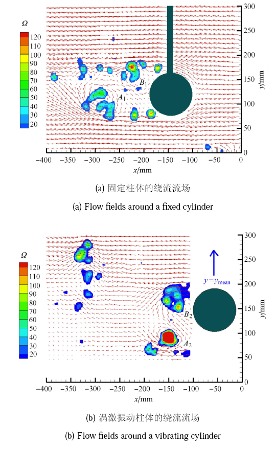
图9 给出了间距比 $e/D =1.00$、流速 $U =0.20$m/s ($Re =1.60 \times 10^{4}$) 条件下,振动柱体和固定柱体绕流瞬时流场叠加旋流强度云图的对比. 从固定柱体的瞬时流场叠加旋流强度 云图(图9(a))可以看出:柱体下表面旋涡 “$A_{1}$” 脱落并向下游移动;柱体上表面旋涡 “$B_{1}$” 刚刚脱落,最大旋流 强度值约为 120s$^{ - 2}$. 频谱分析发现涡脱落频率满足斯特劳哈尔定律. 图9(b) 为柱体周围瞬时流场叠加旋流强度云图,对应于振动柱体在平衡位置向上运动时刻. 在柱体后方有一对旋转方向相标识码涡 “$A_{2}$”、“$B_{2}$” 从柱体表面脱落,旋流强度最大值为 600s$^{- 2}$,这相对于固定柱体有显著增大. 频标识码发现,涡脱落频率被柱体振动频率所控制而发生锁频现象,涡脱落频率不再遵循斯特劳哈尔定律. 实验观测还发现,当标识码速至升速过程振动触发时的临界速度时,尾迹涡旋强度仍较大且涡脱落频率与柱体振动频率保持一致;涡脱落趋于维持标识码态而难以立刻解锁,因此柱体振动仍可持续至较小的约减速度才停振,即涡激振动存在迟滞效应.
图9
 新窗口打开|下载原图ZIP|生成PPT
图9涡激振动柱体与固定柱体的绕流流场对比
Fig.9Comparison of the flow field around a vibrating cylinder with that around a fixed cylinder ($U =0.20$m/s,${Re}=1.60\times 10^{4}$,$e/D=1.00$)}
3.3 涡激振动迟滞效应
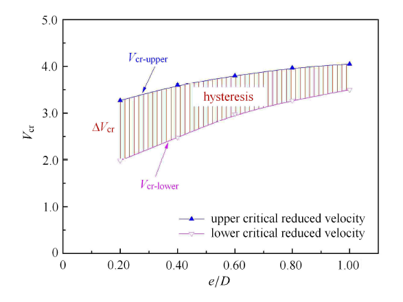
图10给出了涡激振动的上临界速度和下临界速度随着间距比的变化情况. 由图可见,对于较大间距比情况 ($e/D \geqslant 0.80$), 涡激振动触发的上临界约减速度基本保持为常数,约为 4.0;随着间距比的减小,涡激振动触发的上临界速度逐渐减小,这说明标识码动触发更容易. 在本文所研究的间距比范围内 ($0.2 \leqslant e /D \leqslant 1.0$),涡激振动的下临界速度明显小于上临界速度,可见升降流速作用下可使得涡激振动响应产生明显的迟滞效应.图10
 新窗口打开|下载原图ZIP|生成PPT
图10涡激振动的上临界和下临界速度随间距比变化
Fig.10Variation of the upper-critical and the lower-critical reduced velocity for the VIVs of a cylinder with the gap-to-diameter ratio ($D =0.08$m,$m^*=1.85$,$f_{\rm n} =0.57$Hz, $\zeta = 1.10\times 10^{ - 2}$,$K_{\rm s}=3.14\times 10^{ - 2}$,${Re}=O(10^{4})$)
本文采用上临界与下临界约减速度的差值 $\Delta V_{\rm cr}$ 表征升降流速过程中柱体涡激振动的迟滞程度. 图11 给出了 $\Delta V_{\rm cr}$ 随间距比的变化及对应的拟合趋势线. 可以看出,涡激振动迟滞程度随着间距比的减小而增大. 当间距比 $e/D =0.20$ 时,$\Delta V_{\rm cr}$ 值可以达到升速阶段涡激振动触发上临界速度 $V_{\rm cr - upper}$ 的 40${\%}$ . 海底管道涡激振动触发临界速度与管道最大允许悬跨长度密切相关,可见工程设计应当考虑涡激振动的迟滞效应. 涡激振动迟滞的发生通常伴随振动幅值的阶跃(见图5). 图12 给出了不同间距比条件下涡激振动迟滞对应的柱体振动幅值变化情况. 当柱体逐渐接近壁面时,涡激振动迟滞发生时相应的柱体振幅阶跃值则逐渐减小. 值得注意的是,本实验研究所观测的现象和规律是在系统的质量-阻尼组合参数较小(小 $K_{\rm s}$ 数)等条件下获得的.
图11
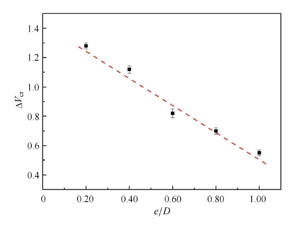 新窗口打开|下载原图ZIP|生成PPT
图11涡激振动迟滞程度随间距比的变化
Fig.11Variation of the hysteresis extent in VIVs with the gap-to-diameter ratio ($D =0.08$m,$m^*=1.85$,$f_{\rm n} =0.57$Hz, $\zeta = 1.10\times 10^{ - 2}$,$K_{\rm s}=3.14\times 10^{ - 2}$,${Re}=O(10^{4})$)
图12
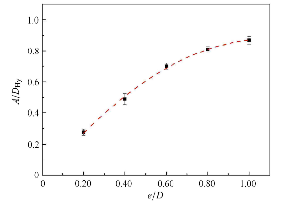 新窗口打开|下载原图ZIP|生成PPT
图12迟滞发生时的对应振幅随间距比变化
Fig.12Variation of vibration amplitude when hysteresis occurs with gap-to-diameter ratio ($D =0.08$m,$m^*=1.85$,$f_{\rm n} =0.57$Hz, $\zeta = 1.10\times 10^{ - 2}$,$K_{\rm s}=3.14\times 10^{ - 2}$,${Re}=O(10^{4})$)
4 结 论
结合大型流-固-土耦合波流水槽,设计加工了具有微结构阻尼的柱体涡激振动实验模拟装置. 基标识码分析并通过同步测量柱体涡激振动位移时程和绕流流场变化,实验研究了升速和降速过程中柱体涡激振动的临界速度以及标识码应规律,着重探讨了小质量-阻尼组合参数条件下近壁面柱体涡激振动的迟滞效应. 得出以下结论:(1) 在升速流动过程中,近壁面柱体涡激振动触发的上临界约减速度呈现随间距比的减小而减小的变化趋势. 对于较大间 距比情况 ($e/D \geqslant 0.80$),上临界约减速度基本保持为常数 4.0;对于较小间距比情况 ($0.2 \leqslant e/D \leqslant 0.60$),上临界约减速度随着间距比的减小而逐渐减小,这说明涡激振动更易被触发.
(2) 降速流动引起涡激振动停振所对应的下临界速度明显小于升速流动诱导涡激振动触发所对应的上临界速度,即升降流速标识码柱体涡激振动具有迟滞效应. 本文建议采用上临界与下临界约减速度差值表征涡激振动迟滞程度,并发现在柱体间距比范围内 ($0.2 \leqslant e/D \leqslant 1.0$),涡激振动迟滞程度随间距比减小呈线性增大趋势.
(3) 涡激振动迟滞现象通常伴随振动的幅值阶跃和频率跃迁. 振幅阶跃峰值随着间距比减小而非线性减小. 升速标识码涡激振动触发的频率跃迁峰值则随着间距比的减小而增大;然而,在降速过程中涡激振动趋于标识码的振动频率并未发生明显跃迁,而是随约减速度的减小逐渐趋于稳定值.
参考文献 原文顺序
文献年度倒序
文中引用次数倒序
被引期刊影响因子
[本文引用: 2]
DOIURL [本文引用: 1]
DOIURL
//
[本文引用: 1]
[Master’s Thesis].
[本文引用: 2]
DOIURLPMID [本文引用: 1]

Vortex streets formed behind oscillating bluff bodies consist of arrays of groups of two, three, or four vortices classified as 2S, P+S, and 2P shedding modes, respectively. The prevailing dominant mode depends primarily on the amplitude and the frequency of the oscillation and on the Reynolds number. We investigate the effect of noise at the inflow on the stability of these vortex modes in laminar flow past a circular cylinder. We employ stochastic simulations based on a new polynomial chaos method to study the shedding-mode switching from a P+S pattern to a 2S mode in the presence of noise.
[PhD Thesis].
DOIURL
DOIURL
Abstract
This is a comprehensive review of the progress made during the past two decades on vortex-induced vibration (VIV) of mostly circular cylindrical structures subjected to steady uniform flow. The critical elements of the evolution of the ideas, theoretical insights, experimental methods, and numerical models are traced systematically; the strengths and weaknesses of the current state of the understanding of the complex fluid/structure interaction are discussed in some detail. Finally, some suggestions are made for further research on VIV.DOIURLPMID
A vortex-induced vibration (VIV) experiment on a standing variable-tension deepsea riser was conducted to investigate the applicability and sensitivity of Bare Fiber Bragg Grating (BFBG) sensor technology for testing deepsea riser vibrations. The dominant frequencies, dimensionless displacements, in-line and cross-flow couplings of the riser VIV under different top tensions were observed through wavelet transform and modal decomposition. The result indicated that, excited by the same external flow velocities, the cross-flow and in-line dominant frequencies of the riser both decreased with increasing top tension. In terms of displacement responses, increasing top tension caused the root mean square (RMS) displacement to decrease and the vibration amplitude to reduce. In terms of cross-flow and in-line coupling, the closer a location is to the ends of the riser, the smaller the trajectory is and the more standard the &quot;8&quot; becomes. During top tension increases, there exists a &quot;lag&quot; in the time when the riser's vibration trajectory becomes an &quot;8&quot;. The Slalom Surround Installation approach can effectively prevent the local breakage of the optical fiber string. BFBG sensor technology can give an accurate presentation of the displacement time history, vibration amplitude and frequency of the riser, provides a clear picture of how the riser's mode and VIV evolve as a function of flow velocity.
DOIURL
This paper reviews the progress made during the past decade on vortex-induced vibration (VIV) of long slender cylindrical structures. When the aspect ratio, which is defined as the ratio of length to diameter for cylindrical structures, is large enough (10(2)-10(3)), some unexpected phenomena occur, e.g., dual resonance, multi-mode vibration, unsteady lock-in, the third and higher harmonic fluid forces and traveling wave dominant response, as summarized in this paper. In addition, a brief outline is given of numerical methods used in predicting the response of long slender cylinder undergoing VIV. Crown Copyright (C) 2011 Published by Elsevier Ltd.
[本文引用: 1]
[本文引用: 1]
[本文引用: 1]
DOIURLPMID [本文引用: 3]
The field of neuroimaging is rapidly adopting a more reproducible approach to data acquisition and analysis. Data structures and formats are being standardised and data analyses are getting more automated. However, as data analysis becomes more complicated, researchers often have to write longer analysis scripts, spanning different tools across multiple programming languages. This makes it more difficult to share or recreate code, reducing the reproducibility of the analysis. We present a tool, Porcupine, that constructs one's analysis visually and automatically produces analysis code. The graphical representation improves understanding of the performed analysis, while retaining the flexibility of modifying the produced code manually to custom needs. Not only does Porcupine produce the analysis code, it also creates a shareable environment for running the code in the form of a Docker image. Together, this forms a reproducible way of constructing, visualising and sharing one's analysis. Currently, Porcupine links to Nipype functionalities, which in turn accesses most standard neuroimaging analysis tools. Our goal is to release researchers from the constraints of specific implementation details, thereby freeing them to think about novel and creative ways to solve a given problem. Porcupine improves the overview researchers have of their processing pipelines, and facilitates both the development and communication of their work. This will reduce the threshold at which less expert users can generate reusable pipelines. With Porcupine, we bridge the gap between a conceptual and an implementational level of analysis and make it easier for researchers to create reproducible and shareable science. We provide a wide range of examples and documentation, as well as installer files for all platforms on our website: https://timvanmourik.github.io/Porcupine. Porcupine is free, open source, and released under the GNU General Public License v3.0.
//
[本文引用: 1]
DOIURL
DOIURL
[本文引用: 1]
DOIURL [本文引用: 1]
[本文引用: 1]
DOIURL [本文引用: 1]
DOIURL [本文引用: 1]
DOIURL
Abstract
Flow characteristics in the near wake of a circular cylinder located close to a fully developed turbulent boundary layer are investigated experimentally using particle image velocimetry (PIV). The Reynolds number based on the cylinder diameter (D) is 1.2×10⁴ and the incident boundary layer thickness (δ) is 0.4D. Detailed velocity and vorticity fields in the wake region (0<x/D<6) are given for various gap heights (S) between the cylinder and the wall, with S/D ranging from 0.1 to 1.0. Both the ensemble-averaged (including the mean velocity vectors and Reynolds stress) and the instantaneous flow fields are strongly dependent on S/D. Results reveal that for S/D?0.3, the flow is characterized by the periodic, Kármán-like vortex shedding from the upper and lower sides of the cylinder. The shed vortices and their evolution are revealed by analyzing the instantaneous flow fields using various vortex identification methods, including Galilean decomposition of velocity vectors, calculation of vorticity and swirling strength. For small and intermediate gap ratios (S/D?0.6), the wake flow develops a distinct asymmetry about the cylinder centreline; however, some flow quantities, such as the Strouhal number and the convection velocity of the shed vortex, keep roughly constant and virtually independent of S/D.DOIURL
DOIURL [本文引用: 1]
DOIURL [本文引用: 1]
Abstract
Most of the existing researches either focus on vortex-induced vibrations (VIVs) of a pipeline near a rigid boundary, or on seabed scour around a fixed pipeline. In this study, the coupling effects between pipeline vibration and sand scour are investigated experimentally. Experimental results indicate that there often exist two phases in the process of sand scouring around the pipeline with an initial embedment, i.e.Phase I: scour beneath pipe without VIV, and Phase II: scour with VIV of pipe. During Phase II, the amplitude of pipe vibration gets larger and its frequency gets smaller while the sand beneath the pipe is being scoured, and finally the pipe vibration and sand scour get into an equilibrium state. This indicates that sand scouring has an influence upon not only the amplitude of pipe vibration but also its frequency. Moreover, the equilibrium scour depth decreases with increasing initial gap-to-diameter ratio for both the fixed pipes and vibrating pipes. For a given value of initial gap-to-diameter ratio (e0/D), the vibrating pipe may induce a deeper scour hole than the fixed pipe in the examined range of initial gap-to-diameter ratios (−0.25<e0/D<0.75).DOIURL [本文引用: 2]
In this study, the vortex-induced vibrations of a cylinder near a rigid plane boundary in a steady flow are studied experimentally. The phenomenon of vortex-induced vibrations of the cylinder near the rigid plane boundary is reproduced in the flume. The vortex shedding frequency and mode are also measured by the methods of hot film velocimeter and hydrogen bubbles. A parametric study is carried out to investigate the influences of reduced velocity, gap-to-diameter ratio, stability parameter and mass ratio on the amplitude and frequency responses of the cylinder. Experimental results indicate: (1) the Strouhal number (St) is around 0.2 for the stationary cylinder near a plane boundary in the sub-critical flow regime; (2) with increasing gap-to-diameter ratio (e 0/D), the amplitude ratio (A/D) gets larger but frequency ratio (f/f n ) has a slight variation for the case of larger values of e 0/D (e 0/D > 0.66 in this study); (3) there is a clear difference of amplitude and frequency responses of the cylinder between the larger gap-to-diameter ratios (e 0/D > 0.66) and the smaller ones (e 0/D < 0.3); (4) the vibration of the cylinder is easier to occur and the range of vibration in terms of V r number becomes more extensive with decrease of the stability parameter, but the frequency response is affected slightly by the stability parameter; (5) with decreasing mass ratio, the width of the lock-in ranges in terms of V r and the frequency ratio (f/f n ) become larger.
//
[本文引用: 1]
[本文引用: 1]
[本文引用: 1]
DOIURL [本文引用: 2]
DOIURL [本文引用: 1]
DOIURL [本文引用: 1]
DOIURL [本文引用: 1]
DOIURL [本文引用: 1]
DOIURL
DOIURL [本文引用: 1]
The hysteretic behaviour of a freely vibrating cylinder, near the low-Reynolds-number end of synchronization/lock-in, in the laminar regime is investigated. Computations are carried out using a stabilized finite-element method. The flow remains two-dimensional in this Reynolds number regime. This is verified via comparison of two- and three-dimensional computations. The cylinder is free to undergo crossflow as well as in-line vibrations. The combined effect of mass ratio (1 <= m* <= 100) and blockage (0.25% <= B <= 12.5%) is studied in detail. The existence of a critical mass ratio (m(cr)* = 10.11), below which hysteresis disappears for an unbounded flow situation, is identified. For higher mass ratio the hysteretic behaviour is observed for all blockage. However, the hysteresis loop width is found to vary with B; its variation with m* and B is studied. The concept of critical blockage B-cr is introduced. For B <= B-cr the response of the cylinder is virtually the same as that in an unbounded flow domain. The variation of B-cr with m* is investigated. Furthermore, B-cr is found to vary non-monotonically with m* for m* <= m(cr)* and is almost constant for m* >= 20. The effect of damping, as well as restricting the cylinder to undergo transverse vibrations only, on the hysteresis behaviour is studied. The transverse-only motion leads to a larger hysteresis loop width compared with the transverse and the in-line motion of the cylinder. An attempt is made to explain this by comparing the results from forced vibrations.
DOIURL [本文引用: 1]
对雷诺数Re = 100 间距比s/D = 2.5 和5.0 的并列双圆柱流致振动进行了数值模拟研究, 其中圆柱质量比m = 2.0, 折合流速Ur 在2.0~10.0 之间, 两圆柱仅能做横流向振动. 研究发现, 当间距比s/D = 2.5 时, 在折合流速4.4 < Ur< 4.8区间内, 两圆柱流致振动响应出现不对称振动现象, 在折合流速4.4 < Ur< 4.8 区间内, 两圆柱流致振动响应出现对称性迟滞现象; 而当间距比s/D = 2.5时, 圆柱流致振动响应与单圆柱涡激振动响应相似, 没有出现不对称振动和对称性迟滞现象. 在不对称振动区间内, 两圆柱的升、阻力参数也出现了不相等的情况. 此外, 当两圆柱不对称振动时, 圆柱间隙流稳定地偏斜向其中的一个圆柱; 相应地, 尾涡也出现了宽窄不等的模式. 窄尾流圆柱的振幅和升、阻力均较宽尾流圆柱的大. 通过对比不对称振动现象发生前后的尾涡模式, 对新现象的产生机制进行了阐述.
DOIURLPMID [本文引用: 1]
Although image-based methods like MRI are well-developed, numerical simulation can help to understand human heart function. This function results from a complex interplay of biochemistry, structural mechanics, and blood flow. The complexity of the entire system often causes one of the three parts to be neglected, which limits the truth to reality of the reduced model. This paper focuses on the interaction of myocardial stress distribution and ventricular blood flow during diastole and systole in comparison to a simulation of the same patient-specific geometry with a given wall movement (Spiegel, Str?mungsmechanischer Beitrag zur Planung von Herzoperationen, 2009). The orthotropic constitutive law proposed by Holzapfel et al. (Philos. Trans. R. Soc. Lond. Ser. A, 367:3445-3475, 2009) was implemented in a finite element package to model the passive behavior of the myocardium. Then, this law was modified for contraction. Via the ALE method, the structural model was coupled to a flow model which incorporates blood rheology and the circulatory system (Oertel, Prandtl-Essentials of Fluid Mechanics, 3rd edn, Springer Science + Business Media, 2010; Oertel et al., Modelling the Human Cardiac Fluid Mechanics, 3rd edn, Universit?tsverlag Karlsruhe, 2009). Comparison reveals a good quantitative and qualitative agreement with respect to fluid flow. The motion of the myocardium is consistent with physiological observations. The calculated stresses and the distribution are within the physiological range and appear to be reasonable. The coupled model presented contains many features essential to cardiac function. It is possible to calculate wall stresses as well as the characteristic ventricular fluid flow. Based on the simulations we derive two characteristics to assess the health state quantitatively including solid and fluid mechanical aspects.
[本文引用: 1]
