 , 李杰, 张恒
西北工业大学航空学院,西安 710072
DIMPLE'S VORTEX ANALYSIS BASED ON EIGENVALUE OF VELOCITY GRADIENT TENSOR1)
LiuJing, LiJie, ZhangHeng中图分类号:O351.2,V211
文献标识码:A
通讯作者:
收稿日期:2018-08-6
网络出版日期:2019-05-18
版权声明:2019力学学报期刊社 所有
基金资助:
作者简介:
-->
展开
摘要
关键词:
Abstract
Keywords:
-->0
PDF (8374KB)元数据多维度评价相关文章收藏文章
本文引用格式导出EndNoteRisBibtex收藏本文-->
引 言
在现代高性能涡轮叶片设计中,叶片内部冷却技术非常重要. 各国的传热工作者都在努力寻找新的具有优良传热------流阻特性的冷却技术,其中最具竞争力的就是基于旋涡的强化传热技术[1-3]. 陷窝强化传热技术正是建立在产生有序和小而有力的旋涡流动结构上[4-10]. 诱导的旋涡强度越大,对流场的诱导速度就越大,对流传热效果就越好. 故旋涡的定性分析和定量分析对陷窝的强化传热优化设计研究具有很重要的意义.旋涡分析包括旋涡定性分析和旋涡定量分析. 旋涡的定性分析方法比较成熟,目前有物面奇点分析方法、分离线提取、再附线提取、涡核线提取、涡核截面流态分析和破裂点位置分析等方法. 利用这些方法可以进行清晰的旋涡结构定性分析.
研究者曾经使用过涡核压力梯度、静压值、涡量值、涡量面积分和涡核周围切向速度分布等来进行旋涡强度定量分析.张文升等[11]表示从流线卷起的紧密程度和涡核向外的总压变化可判断旋涡的强度.顾蕴松等[12]认为涡量是旋涡强度的一种更具物理意义的度量.高翔等[13]表明涡核静压降低、径向逆压梯度增大,说明旋涡强度增大.张华等[14]表示涡强可用局部涡量与等涡量线所包围面积的乘积估算,其变化趋势可用峰值涡量定性地近似表示.
但这些方法均有其弊端:涡核压力梯度值不易计算;涡核静压值容易受背景静压值影响,尤其对于存在于背压区的旋涡,涡核静压值受环境静压值的影响较大;涡量值易受边界层集中涡量影响,边界层脱落集中涡量层具有高涡量,当旋涡处于边界层脱落集中涡量区域时,涡核涡量不能代表旋涡强度;切向速度分布需要繁复的空间数据提取.
对于陷窝诱导的旋涡,不同深宽比诱导的旋涡结构不同、分离方式不同、背景压力不同,使得目前的旋涡强度判断方法失效,有必要发展一种普适的旋涡强度定量判断方法.
早在1992年,张涵信等[15-16]就通过旋涡涡核处的轴向速度分布和轴向加速度分布来定性分析旋涡发展过程,认为轴向加速度的正负是涡核垂直截面流线形态的决定因素,并由此给出旋涡破裂的定义. 轴向加速度是速度梯度张量的实特征值. 1999年,Zhou等[17]提出旋转角速度$\lambda _{\rm ci} $ 准则,用来从附面层中识别发卡涡,此旋涡识别方法在同类方法中被认为是最有效的[18-26]. $\lambda _{\rm ci}$是速度梯度张量复特征值的虚部,代表旋涡在局部旋转平面的旋转角速度. 并指出旋涡涡核处速度梯度张量的特征值为一个实特征量和两个复特征值,实特征值为轴向加速度,复特征值的实部为径向加速度,虚部为旋转角速度. 特征向量形成一个局部坐标系,一个方向指向涡核方向,另两个方向在垂直于涡核方向的截面上. 可见特征向量具有方向指示的作用,特征值具有强度定量的作用.
为了定量呈现旋涡的整体性质,本文结合文献[15,16]的旋涡涡核数据整体分析理念和文献[17]的速度梯度张量特征值和特征向量分析结论,探索旋涡整体定量分析方法. 简言之,本文提取旋涡的全程涡核数据,计算涡核线处速度梯度张量的特征值和特征向量,利用得到的数据进行旋涡整体定量分析. 以陷窝诱导旋涡为例,进行旋涡结构定性分析和旋涡强度定量分析,及深宽比对旋涡强度的影响分析.
1 涡核速度梯度张量特征值方法
速度是流场的核心变量,速度梯度张量涵盖了速度变化的全部信息,速度梯度张量特征值定量表达了速度变化的幅度. 对于旋涡,涡核集中了旋涡速度变化的关键信息. 为获得旋涡的特征信息,下面分析涡核速度梯度张量特征值的变化.在笛卡尔坐标中,旋涡涡核处的速度梯度张量${\pmb D}$可以被简化为
$$ {\pmb D} = \left[ {d_{ij} } \right] = \left[ v_{\rm r} \ \ v_{\rm cr} \ \ v_{\rm ci} \right] \,\left[\!\!\begin{array}{ccc} \lambda _{\rm r} & 0 & 0 \\ 0 & \lambda _{\rm cr} & \lambda _{\rm ci} \\ 0 & - \lambda _{\rm ci} & \lambda _{\rm cr} \end{array}\!\!\right]\,\left[ {v_{\rm r} } \ \ {v_{\rm cr} } \ \ {v_{\rm ci} } \right]^{ - 1} (1) $$
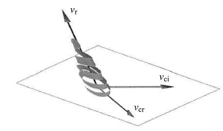
其中,$\lambda _{\rm r} $是和$v_{\rm r} $对应的实特征值,$\lambda _{\rm cr} \pm \lambda_{\rm ci} $是和复特征向量$v_{\rm cr} \pm v_{\rm ci}$对应的复特征值. 涡核局部流线及特征向量示意图如图1,从图中涡核局部流线及特征向量示意图可见,在涡核区域特征向量分别沿着旋涡的轴向、径向和切向,特征值代表沿该方向的加速度.
 显示原图|下载原图ZIP|生成PPT
图1涡核局部流线及特征向量示意图[
-->Fig. 1Vortex core local streamline and eigenvector schematic[
-->
 显示原图|下载原图ZIP|生成PPT
图2计算模型图
-->Fig. 2Computational model
-->
 显示原图|下载原图ZIP|生成PPT
图3数值模拟和实验结果对比
-->Fig. 3Numerical simulation and experimental comparison
-->
在由特征向量$\left\{ {v_{\rm r}, v_{\rm cr} , v_{\rm ci} }\right\}$决定的曲线局部坐标系中,局部流线可以表示为
$$ \left.\begin{array}{l} y_1 (t) = C_{\rm r} \exp \lambda _{\rm r} t y_2 (t) = \exp \lambda _{\rm cr} t\left[ {C_c^{(1)} \cos (\lambda _{\rm ci} t) + C_c^{(2)} \sin (\lambda _{\rm ci} t)} \right] y_3 (t) = \exp \lambda _{\rm cr} t\left[ {C_c^{(2)} \cos (\lambda _{\rm ci} t) - C_c^{(1)} \sin (\lambda _{\rm ci} t)} \right] \end{array}\!\!\right\} (2) $$
从局部流线中可见,$\lambda _{\rm ci}$表示了流线局部旋转角速度的大小,所以$\lambda _{\rm ci}$被定义为旋转角速度,代表旋涡旋转角速度的大小;$\lambda _{\rm r}$表示旋涡的轴向加速度;$\lambda _{\rm cr} $表示径向加速度.
对于不可压流动,由特征向量所在坐标系下的连续方程得
$$ \dfrac{\partial u}{\partial x} + \dfrac{\partial v}{\partial y} + \dfrac{\partial w}{\partial z}= \qquad \lambda _{\rm r} + \lambda _{\rm cr} + {\rm i}\lambda _{\rm ci} + \lambda _{\rm cr} - {\rm i}\lambda_{\rm ci}= \qquad \lambda _{\rm r} + 2\lambda _{\rm cr} = 0 (3) $$
可见,旋涡的径向流动加速度和轴向流动加速度具有严格的定量关系.
在涡核垂直截面,$ r$半径处径向速度满足
$$\dfrac{v_{\rm cr} \left( { r} \right) - v_{\rm cr} \left( 0 \right)}{ r} = \lambda _{\rm cr} (4)$$
由于涡核的径向速度$v_{\rm cr} \left( 0 \right)$满足
$$v_{\rm cr} \left( 0 \right) = 0 (5)$$
故$ r$半径处的径向速度$v_{\rm cr} \left( { r} \right)$可表示为
$$v_{\rm cr} \left( { r} \right) = \lambda _{\rm cr} r = - \dfrac{1}{2}\lambda_{\rm r} r (6)$$
对于旋涡垂直涡核截面流线图,微元$ r$半径处的径向速度的正负决定了涡核垂直截面局部流体是汇聚还是扩散. 当$v_{\rm cr} \left( { r} \right) < 0$,径向速度指向涡核,流体汇聚,截面流态是稳定的向心螺旋线;当$v_{\rm cr} \left( { r} \right) > 0$,径向速度背向涡核,流体扩散,截面流态是不稳定的向外螺旋线.
由 式(5)和式(6)知,5个定量表达旋涡的变量($\lambda _{\rm r} $,$\lambda _{\rm cr} $, $\lambda _{\rm ci}$,$v_{\rm r} $,$v_{\rm cr} $)缩减为3个独立变量($\lambda _{\rm r}$,$\lambda _{\rm ci} $,$v_{\rm r}$)或者($v_{\rm cr} \left( { r} \right)$,$\lambda _{\rm ci} $,$v_{\rm r}$). $v_{\rm cr} \left( { r}\right)$表示微元$ r$半径处的径向速度,$v_{\rm r} $表示旋涡轴向速度;$\lambda _{\rm ci}$表示旋涡的旋转角速度.
本方法基于特征向量的移动标架坐标系,提取到了丰富的旋涡参数信息:轴向速度、轴向加速度、径向速度、径向加速度、旋转角速度以及旋涡局部坐标系.利用这些参数表达的张涵信等[15-16]旋涡整体发展过程如下.
(1) 第一阶段:$v_{\rm r} > 0$,$v_{\rm cr} \left( { r} \right) <0$,涡核垂直截面流线是稳定的螺旋点形态,旋涡处于汇聚段,轴向速度增加.
(2) 第二阶段:$v_{\rm r} > 0$,$v_{\rm cr} \left( { r} \right) =0$,涡核垂直截面流线是中心点形态,轴向速度达到最大值.
(3) 第三阶段:$v_{\rm r} > 0$,$v_{\rm cr} \left( { r} \right) >0$,涡核垂直截面流线是不稳定的螺旋点形态,旋涡处于扩散段,轴向速度减小.
(4) 第四阶段:$v_{\rm r}= 0$,$v_{\rm cr} \left( { r} \right) > 0$,旋涡破裂.
(5) 第五阶段:$v_{\rm r} < 0$,$v_{\rm cr} \left( { r} \right) > 0$,涡核垂直截面流线是不稳定的螺旋点形态,旋涡处于扩散段,轴向速度为负,旋涡破裂后轴向逆流.
可见,$v_{\rm cr} \left( { r} \right)$和$v_{\rm r}$的正负决定了旋涡发展的不同阶段. 下面分析$\lambda _{\rm ci} $的全程变化过程. 涡核旋转角速度$\lambda _{\rm ci}$的变化反映了旋涡涡量汇聚/扩散强度和耗散强度的权衡结果.
$\lambda _{\rm ci} $增大的因素: 径向汇聚($v_{\rm cr} \left( { r} \right) < 0$);$\lambda _{\rm ci} $减小的因素: (1) 径向扩散($v_{\rm cr} \left( { r} \right) > 0$); (2)黏性耗散和数值耗散.
对于低雷诺数流动,对流项和黏性项量级相近,对流项的数值耗散对于黏性项的数值模拟影响不大,得到的涡核旋转角速度可以真实反应旋涡强度. 对于高雷诺数流动,对流项比黏性项数量级大,对流项的数值误差数值耗散和黏性项具有相近的数量级,过大的数值耗散影响黏性项的准确模拟,数值模拟得到的涡核旋转角速度比真实物理涡核旋转角速度小. 黏性耗散和数值耗散是全程削弱涡核旋转角速度的因素.
在旋涡轴向发展分段中,第一阶段具有径向汇聚和数值/黏性耗散,一个为增大因素,另一个为减小因素;第二阶段至第五阶段具有径向扩散和数值/黏性耗散,两种都是减少因素.
$\lambda _{\rm ci}$的变化是径向汇聚强度、数值/黏性耗散强度的综合权衡结果. 径向汇聚强度大于数值/黏性耗散强度时,旋转角速度增加;径向汇聚强度小于数值/黏性耗散强度时,旋转角速度减小. 闭式分离旋涡的径向汇聚弱,通常$\lambda _{\rm ci} $在旋涡的第一阶段起始位置附近达到最大值. 开式分离旋涡的径向汇聚强.
数值/黏性耗散较强旋涡的$\lambda _{\rm ci}$在第一阶段中间取得最大值;数值/黏性耗散较弱旋涡的$\lambda _{\rm ci}$在第一阶段结尾处取得最大值.
综上,3个独立变量($\lambda _{\rm r}$,$\lambda _{\rm ci} $,$v_{\rm r}$)中,$\lambda _{\rm r}$越大,则$\lambda _{\rm ci} $和$v_{\rm r} $的增大量越大. 3个变量可以综合定量分析旋涡特性.依据点涡强度的定义,建议将$\lambda _{\rm ci} $最大值作为衡量旋涡强度的准则.为了避免数值耗散的非物理影响,建议在旋涡定量比较时,使用一致的网格尺度进行旋涡空间离散,确保对比结果的可信性.
数据处理方法:
(1) 利用文献[27,28]的Eigenmode Analysis方法 提取涡核线.
(2) 导出涡核线的位置、速度、速度梯度张量等流场变量至文件.
(3) 用Matlab计算涡核线位置处速度梯度张量的特征值和特征向量.
(4) 结合沿涡核线速度张量的特征值,及涡核轴向速度的变化来分析旋涡的特性.
本方法的优势:
(1) 数据处理方式简单通用. 单次数据处理,即可实现旋涡的完全分析. 无需截面数据提取、截面压力梯度求解和切向速度分布对比等复杂且不通用的处理办法.
(2) 适用范围广,具有通用性. 本方法适用于所有旋涡的分析.
(3) 具有不受分离方式影响、不受背景压力影响、提取到的涡核旋转角速度是旋涡本质属性的优良特性.
2 陷窝诱导旋涡分析
2.1 物理模型和数值计算方法
数值模型为壁面布置陷窝的管道内流. 矩形计算区域长406.4,mm,宽254,mm,高100,mm. 流向为$x$向,宽为$y$向,高为$z$向. 陷窝布置在管道的底板上,陷窝中心和底板中心重合. 陷窝表面直径为25.4,mm.侧壁为对称面,顶面为对称面.为消除入口段影响,计算入口边界设为管道充分发展边界条件[29-30],初始入口边界条件的来流速度为4,m/s.陷窝和地板为恒热流密度300,W/m$^2$. 基于入口平均速度和陷窝表面直径的雷诺数为3375,假设空气不可压缩.本文用Fluent进行两平板间充分发展流动定常RANS数值模拟. 计算选择基于压力的求解器,速度压力耦合采用Coupled方式.湍流模拟选择$k$-$\omega$ SST湍流模型. 动量方程,湍流强度$k$,比耗散率$\omega$和能量方程的对流项离散采用三阶MUSCL格式.本文通过涡核速度梯度张量特征值和特征向量来分析旋涡的发展过程和旋涡强度. 选择深宽比为0.06,0.18和0.30陷窝诱导旋涡进行分析对比.
用ICEM生成多块结构网格. 尽量保持网格方向和流动方向的一致性以及较好的正交性和较小的长宽比. 无滑移物面的法向第一层网格满足$y^+<1$,并在黏性底层$(y^+<10)$的区域有多于10个网格. 总网格单元数为1.7$\times $10$^6$.
为验证本文数值模拟的准确性,采用和文献[10]实验中一致的模型和边界条件对陷窝强化对流传热进行数值模拟,并与文献中的实验结果进行对比,结果如图所示. 光滑管道计算值为$Nu_0$.计算与实验结果的$Nu/Nu_0$相对误差在6%内,说明本文数值模拟方法的可靠性.
2.2 0.06深宽比陷窝诱导旋涡分析
图4是深宽比为0.06陷窝的空间流线、展向无量纲速度大小分布和涡核展向速度梯度张量特征值分布.从图4(a)可见,深宽比0.06陷窝内,流动分离,旋涡从对称面向两侧发展,涡结构为马蹄涡型.图4(b)和图4(c)是无量纲旋涡轴向速度方向和大小:从速度方向来看,旋涡向两侧发展;从速度大小来看,无量纲轴向速度小于0.005,旋涡的轴向速度很小,属于闭式分离.图4(d)是旋涡涡核局部速度梯度张量的特征值中的一个实特征值$\lambda _{\rm r} $,两个共轭复特征值的实部$\lambda_{\rm cr} $和虚部$\lambda _{\rm ci} $. 从沿展向的$\lambda _{\rm ci}$分布可见,旋涡的最大旋转角速度为20,位于对称面,沿展向发展, $\lambda _{\rm ci}$降低.闭式分离径向汇聚较小,随着黏性耗散和数值耗散,涡核旋转动量得不到补给,旋转角速度降低.从轴向加速度$\lambda_{\rm r}$分布和无量纲轴向速度分布可见,在旋涡发展过程中轴向加速度为正,这和旋涡半径逐渐收缩有关,属于闭式旋涡发展的第一阶段. 涡核最大旋转角速度为20,最大轴向无量纲速度为2.390$\times$10$^{-3}$,最大轴向加速度为2.986.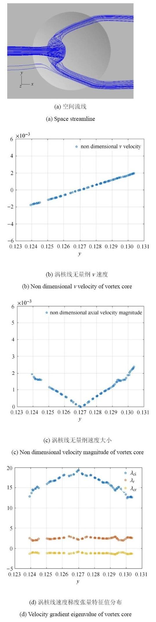 显示原图|下载原图ZIP|生成PPT
图4陷窝0.06内旋涡性质图
-->Fig. 4Vortex property of 0.06 dimple
-->
2.3 深宽比0.18陷窝诱导旋涡分析
图5是深宽比0.18陷窝的空间流线、展向无量纲速度大小分布和涡核展向速度梯度张量特征值分布. 从图5(a)可见,旋涡结构是对称类龙卷风涡结构.来流流线从陷窝两侧的分离螺旋点卷入陷窝,在沿涡核向对称面发展的过程中,突然膨胀,旋涡破裂.图5(b)和图5(c)分别给出涡核轴向速度的方向和大小,结合图5(b)和图5(c)得出涡核轴向速度的变化过程,轴向速度增大至0.015,后减小至0. 在轴向速度等于零的点旋涡破裂. 图5(d)为涡核速度梯度张量特征值图.从轴向无量纲速度大小分布图中可见:在旋涡发展第一阶段,$v_{\rm r}> 0$,$v_{\rm cr} < 0$,涡核旋转角速度增大;在旋涡发展第三阶段,$v_{\rm r} >0$,$v_{\rm cr} > 0$,涡核旋转角速度没有明显变化;在旋涡发展第四阶段,在轴向速度等于零的位置,旋涡破裂;在旋涡发展第五阶段,$v_{\rm r} < 0$,$v_{\rm cr} > 0$,涡核存在轴向扩散和径向扩散,涡核旋转角速度迅速下降.涡核最大旋转角速度为117,最大轴向无量纲速度为0.015,27, 最大轴向加速度为31.65.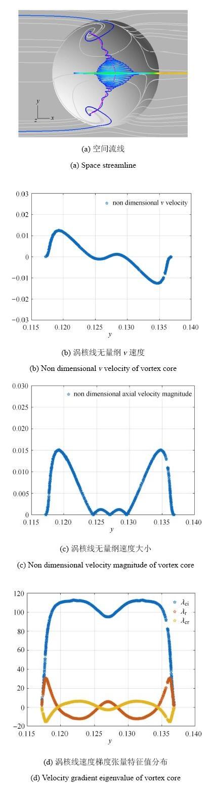 显示原图|下载原图ZIP|生成PPT
图5陷窝0.18内旋涡性质图
-->Fig. 5Vortex property of 0.18 dimple
-->
2.4 深宽比0.30陷窝诱导旋涡分析
图6是深宽比0.30陷窝的空间流线、无量纲$v$速度分布、无量纲速度大小分布和涡核展向速度梯度张量特征值分布.从图6(a)可见,表面流线分布明显不对称:类龙卷风涡所占区域较大的称为主涡;类龙卷风涡所占区域较小的称为次涡.图6(b)给出沿$y$向无量纲$v$速度分布,主类龙卷风涡的旋涡破裂后的逆流旋涡和次类龙卷风涡融合为一个旋涡,此旋涡结构为单类龙卷风涡结构.如图5(c)和图5(d),涡核线的轴向无量纲速度图和速度梯度张量特征值图,主旋涡的轴向速度、轴向加速度、径向加速度和旋转角速度均有两次峰值变化的历程. 说明主漩涡有两个加速汇入段.第一个汇入段为垂直壁面的螺旋点起始的旋涡加速度,汇聚段结束后旋涡最大旋转角速度为223;第二个加速段为旋涡从垂直壁面发展转变为沿流向偏转后的涡量汇入段,汇聚段结束后的旋涡旋转角速度值为126.涡核最大旋转角速度为223,最大轴向无量纲速度为0.040,32,最大轴向加速度为182.8.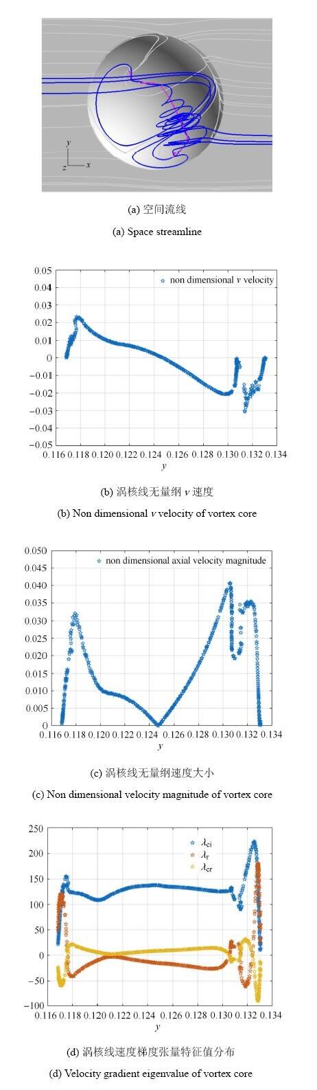 显示原图|下载原图ZIP|生成PPT
图6陷窝0.30内旋涡涡核线性质图
-->Fig. 6Vortex property of 0.30 dimple
-->
2.5 不同深宽比陷窝内旋涡定量分析
从表1可见,从旋涡的最大旋转角速度、最大无量纲轴向速度和最大轴向加速度的定量对比可见:随着深宽比的增大,最大旋转角速度、最大无量纲轴向速度和最大轴向加速度均显著增大,即旋涡强度的排序为$0.06<0.18<0.30$.Table 1
表1
表1不同深宽比陷窝内旋涡强度参数对比
Table 1Vortex strength quantitative comparison between different depth dimple
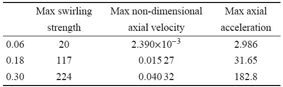 |
新窗口打开
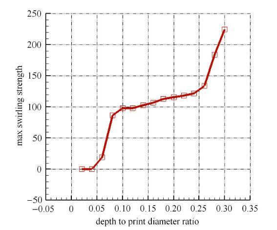
针对陷窝深宽比从0.02至0.30,间隔0.02生成的陷窝模型,利用涡核旋转角速度最大值来分析深宽比变化引起陷窝内旋涡强度的变化. 如图7为陷窝诱导旋涡的旋涡强度计算结果曲线.从结果来看,随着陷窝深宽比的增大,陷窝诱导旋涡强度呈现阶梯状增大,第一阶梯对应着以0.06陷窝为代表的马蹄涡状态;第二阶梯对应着以0.18陷窝为代表的对称类龙卷风状态;第三阶梯对应着以0.30陷窝为代表的单独类龙卷风状态.随着旋涡结构的变化,旋涡强度逐渐增大.
 显示原图|下载原图ZIP|生成PPT
图7旋涡强度随着深宽比的变化曲线
-->Fig. 7Vortex strength change with the ratio of depth to print diameter
-->
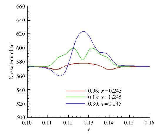
为了证实旋涡强度的变化,在图8陷窝后物面等$x$截线观察Nusselt数分布.陷窝后的Nusselt数分布反映了陷窝后局部对流换热的强度,一般来说对流越强,换热越强,Nusselt数越大. 陷窝的存在诱导旋涡产生,旋涡诱导速度场强化局部强化换热.从Nusselt数的分布可见,Nusselt数最大值顺序为$0.30>0.18>0.06$,这个顺序反应的是局部换热强度的排序,也是旋涡强度的顺序,这证实了旋涡强度方法的正确性. 从陷窝0.06,0.18到0.30,旋涡从闭式分离逐渐变为开式分离,旋涡越接近开式分离,就有越多的涡量和动量从外围汇聚入旋涡涡核内,旋涡涡核的轴向速度和旋转速度就越大,旋涡的强度就越强.
 显示原图|下载原图ZIP|生成PPT
图8陷窝后物面等$x$截线的Nusselt数对比
-->Fig. 8$x$ slice Nusselt number comparison after dimple
-->
3 结 论
针对在旋涡结构、分离方式和背景压力变化下的陷窝内旋涡强度无法定量分析的问题,本文结合张涵信的旋涡整体分析方法[15-16]和文献[17]的旋涡局部坐标系涡核速度梯度张量特征值表示方法,提出采用最大轴向速度、最大轴向加速度和最大旋转角速度定量分析旋涡的方法,并建议将$\lambda_{\rm ci} $最大值作为衡量旋涡强度的准则.采用本文所提出的旋涡定量分析方法分析了不同深宽比陷窝内的旋涡结构,同时定量对比了旋涡强度随着深宽比的变化过程. 研究表明:从陷窝深宽比0.06, 0.18到0.30,最大轴向速度、最大轴向加速度和最大旋转角速度均显著增加,可见旋涡强度依次增加. 涡结构为马蹄涡、对称类龙卷风涡和单类龙卷风涡,旋涡从闭式分离逐渐变为开式分离,最大旋转角速度随着旋涡结构的变化呈现阶梯式增加;表面Nusselt数的分布印证了旋涡强度的变化趋势. 该结论可以为陷窝强化对流传热的优化设计提供支撑.
The authors have declared that no competing interests exist.
参考文献 原文顺序
文献年度倒序
文中引用次数倒序
被引期刊影响因子
| [1] | . 基于涡流发生的凹坑强化换热是一种新型高效的强化换热和冷却技术,其主要特点是传热强度大,流动阻力小,综合传热性能高.通过近十年来凹坑强化换热研究工作的回顾,介绍凹坑壁面的换热阻力特性和涡流结构,并讨论凹坑形状、深度和雷诺数等参数的影响.通过介绍凹坑在旋转通道、圆管和冲击耙面等不同情况下的换热阻力特性,以及与肋等的综合传热性能对比,旨在说明凹坑是一种很具潜力的新型强化换热结构,具有十分广泛的应用前景. . 基于涡流发生的凹坑强化换热是一种新型高效的强化换热和冷却技术,其主要特点是传热强度大,流动阻力小,综合传热性能高.通过近十年来凹坑强化换热研究工作的回顾,介绍凹坑壁面的换热阻力特性和涡流结构,并讨论凹坑形状、深度和雷诺数等参数的影响.通过介绍凹坑在旋转通道、圆管和冲击耙面等不同情况下的换热阻力特性,以及与肋等的综合传热性能对比,旨在说明凹坑是一种很具潜力的新型强化换热结构,具有十分广泛的应用前景. |
| [2] | . 对矩形通道内的球面凹坑壁面进行了传热系数和流动阻力测量,研究了通道Re数和凹坑间距的影响.无量纲流向间距分别为1.5,1.2和0.8.实验发现凹坑面上局部Nu数沿流向和横向变化剧烈.与光滑壁面相比,凹坑面的平均换热增强45%左右,流动阻力增大92%左右,平均综合传热性能增强16%.减小凹坑间距使流动阻力增大,平均换热和平均综合传热性能进一步增强.数据显示Re数对凹坑壁面的换热增强和流动阻力增大的影响相对较小. . 对矩形通道内的球面凹坑壁面进行了传热系数和流动阻力测量,研究了通道Re数和凹坑间距的影响.无量纲流向间距分别为1.5,1.2和0.8.实验发现凹坑面上局部Nu数沿流向和横向变化剧烈.与光滑壁面相比,凹坑面的平均换热增强45%左右,流动阻力增大92%左右,平均综合传热性能增强16%.减小凹坑间距使流动阻力增大,平均换热和平均综合传热性能进一步增强.数据显示Re数对凹坑壁面的换热增强和流动阻力增大的影响相对较小. |
| [3] | . 为了揭示凹坑冷却结构的强化传热机理,基于第三类边界条件下的一维半无限大瞬态导热模型,用红外热成像仪的瞬态测温技术和金属网快速加热技术,对矩形通道内壁面进行了瞬态传热测量,获得了光滑壁面和带有单个球面凹坑壁面的局部对流换热系数分布,并用油-粉末法对凹坑壁面进行了壁面流场显示,实验雷诺数范围1.58×10⁴~6.36×10⁴。实验发现凹坑强化换热与其诱导形成的涡流结构密切相关,单个球面凹坑引起的涡流可以使凹坑下游边缘附近的局部换热最大增强80%左右,凹坑下游尾迹区域的平均换热增强20%~30%。 . 为了揭示凹坑冷却结构的强化传热机理,基于第三类边界条件下的一维半无限大瞬态导热模型,用红外热成像仪的瞬态测温技术和金属网快速加热技术,对矩形通道内壁面进行了瞬态传热测量,获得了光滑壁面和带有单个球面凹坑壁面的局部对流换热系数分布,并用油-粉末法对凹坑壁面进行了壁面流场显示,实验雷诺数范围1.58×10⁴~6.36×10⁴。实验发现凹坑强化换热与其诱导形成的涡流结构密切相关,单个球面凹坑引起的涡流可以使凹坑下游边缘附近的局部换热最大增强80%左右,凹坑下游尾迹区域的平均换热增强20%~30%。 |
| [4] | . react-text: 380 The Air Force Research Laboratory, Propulsion Directorate at Wright Patterson Air Force Base has studied the performance of turbine blade geometries utilizing a large scale, low speed, drawdown wind tunnel in an effort to better understand gas turbine blade aerodynamics. Currently, the Air Force's Unmanned Aerial Vehicle (UAV) Global Hawk has been operated primarily at flight conditions other... /react-text react-text: 381 /react-text [Show full abstract] |
| [5] | |
| [6] | . Experimental results, measured on and above a dimpled test surface placed on one wall of a channel, are given for Reynolds numbers from about 600 to about 11聽000 and ratios of air inlet stagnation temperature to surface temperature ranging from 0.78 to 0.94. These include flow visualizations, and spatially resolved local Nusselt numbers. Ratios of channel height to dimple print diameter of 0.20, 0.25, 0.50, and 1.00 are employed. The ratio of dimple depth to dimple print diameter is 0.2. Visualized flow smoke patterns show that the vortex pairs, which are periodically shed from the dimples, becomes stronger as non-dimensional channel height / decreases. Such behavior is leads to local Nusselt number augmentations at these same locations, which also become larger as / decreases. Local Nusselt number ratios also increase substantially at same locations as / decreases because of buoyancy and variable property influences. |
| [7] | . The paper presents detailed numerical study of heat transfer enhancement by a spherical dimple placed on a wall in a narrow channel. RANS approach with MSST model is applied to investigate the influence of the depth to diameter ratio 螖 and the Reynolds number on the flow and heat transfer. Numerical model was successfully validated using LDV measurements, pressure loss data and LES results. Special attention is paid to identification of the flow topology at different 螖 and Reynolds numbers. Contribution of different heat exchanger surface parts to the heat transfer enhancement is analyzed. Application of entropy production as a criterion of heat exchanger efficiency is discussed. Detailed information gained from the present computations can be used to get a deep insight into flow physics over dimpled surfaces and as a benchmark for validation of numerical and experimental methods. |
| [8] | . Abstract02=0220,000 and Re02=0240,000 the depth to print diameter ratio of Δ02=020.26. Frequency analysis of LES data revealed the presence of dominating frequencies in unsteady flow oscillations. Direct analysis of the flow field revealed the presence of coherent vortex structure inclined to the mean flow. The structure changes its orientation in time causing the long period oscillations with opposite-of-phase motion. Three dimensional proper orthogonal decomposition (POD) analysis is carried out on LES pressure and velocity fields to identify spatio-temporal structures hidden in the random fluctuations. Tornado-like spatial POD structures have been determined inside dimples. |
| [9] | . Instantaneous, dynamic and time-averaged characteristics of the vortex structures which are shed from the dimples placed on one wall of a channel are described. The dimpled test surface contains 13 staggered rows of dimples in the streamwise direction, where each dimple has a print diameter of 5.08 cm, and a ratio of depth to print diameter of 0.2. Considered are Reynolds numbers (based on channel height)ReHfrom 600 to 11鈥000, and ratios of channel height to dimple print diameterH/Dof 0.25, 0.50, and 1.00. For all threeH/D,a primary vortex pair is periodically shed from the central portion of each dimple, including a large upwash region. This shedding occurs periodically and continuously, and is followed by inflow advection into the dimple cavity. The frequency of these events appears to scale on time-averaged bulk velocity and dimple print diameter, which gives nondimensional frequencies of 2.2鈥3.0 for all threeH/Dvalues considered. AsH/Ddecreases, (i) the strength of the primary vortex pair increases, and (ii) two additional secondary vortex pairs (which form near the spanwise edges of each dimple) become significantly stronger, larger in cross section, and more apparent in flow visualization images and in surveys of time-averaged, streamwise vorticity. The locations of these primary and secondary vortex pairs near the dimpled surface coincide closely with locations where normalized Reynolds normal stress is augmented. This evidences an important connection between the vortices, Reynolds normal stress, and mixing. The large-scale unsteadiness associated with this mixing is then more pronounced, and encompasses larger portions of the vortex structure (and thus extends over larger volumes) asH/Dincreases from 0.25 to 1.0. |
| [10] | . Flow structural characteristics over dimple surfaces located on one wall of a rectangular channel with three different dimple depths (δ∕D=0.1, 0.2, and 0.3) are studied experimentally. Reynolds number based on channel heightReHranges from 2100 to 2065000, and the ratio of channel height to dimple print diameterH∕Dis 1.0. Presented are instantaneous flow visualization images, spectra of longitudinal velocity fluctuations, vortex pair frequency information, and time-averaged surveys and profiles of different quantities. Regardless of dimple depth, primary vortex pairs are periodically ejected from the central parts of each dimple and exist in conjunction with edge vortex pairs present near the spanwise edges of staggered dimples. As dimple depth increases, larger deficits of total pressure and streamwise velocity are present, along with higher magnitudes of time-averaged streamwise vorticity, vortex circulation, and longitudinal Reynolds normal stress. Bigger and stronger vortices with increased turbulence transport capabilities are thus produced by deeper dimples. Ensemble-averaged power spectral density profiles show that primary vortex pair ejection frequencies range from7to9Hz, and edge vortex pair oscillation frequencies range from5to7Hz, with similar distributions as the Reynolds number varies, regardless of dimple depth. |
| [11] | . <p>以民用运输机增升装置复杂增升构型气动设计为背景,针对短舱扰流片对增升构型气动性能的影响,借助数值模拟对流动控制效果和影响机理进行研究。数值结果表明:合理的扰流片设计可以明显改善增升装置的气动特性,提高最大升力系数0.3以上,增大失速迎角3°左右。短舱扰流片安装参数研究表明:短舱扰流片产生旋涡强度对其推迟失速的效果有明显影响;在所研究的范围内,短舱扰流片弦向位置明显影响扰流片的当地来流迎角,进而改变所产生旋涡的强度;扰流片的周向安装角主要影响扰流片的来流强度,同样影响所产生旋涡的强度;扰流片面积对提高升力系数贡献不大,主要影响失速形态。</p> . <p>以民用运输机增升装置复杂增升构型气动设计为背景,针对短舱扰流片对增升构型气动性能的影响,借助数值模拟对流动控制效果和影响机理进行研究。数值结果表明:合理的扰流片设计可以明显改善增升装置的气动特性,提高最大升力系数0.3以上,增大失速迎角3°左右。短舱扰流片安装参数研究表明:短舱扰流片产生旋涡强度对其推迟失速的效果有明显影响;在所研究的范围内,短舱扰流片弦向位置明显影响扰流片的当地来流迎角,进而改变所产生旋涡的强度;扰流片的周向安装角主要影响扰流片的来流强度,同样影响所产生旋涡的强度;扰流片面积对提高升力系数贡献不大,主要影响失速形态。</p> |
| [12] | . 大型运输飞机的尾涡系是诱发后继小型飞机空难的重要原因,需要有效的涡控制装置来削弱其强度.通过风洞实验,研究了翼型为NACA23016的矩形半机翼模型翼尖尾涡流动结构和控制方法.应用七孔探针空间流场定量测试技术研究了翼尖涡的流动结构,给出了翼尖尾涡在下游两倍弦长距离内的速度和压力场分布随迎角变化的规律.在机翼翼梢布置不同组合方式的翼梢涡扩散器,来控制翼尖涡.研究结果表明,正负90°和60°安装角的双翼梢涡扩散器可将翼尖涡涡核的静压增加60%以上.其旋涡强度削弱机理为:翼梢涡扩散器将集中的翼尖涡破碎分成两个或 . 大型运输飞机的尾涡系是诱发后继小型飞机空难的重要原因,需要有效的涡控制装置来削弱其强度.通过风洞实验,研究了翼型为NACA23016的矩形半机翼模型翼尖尾涡流动结构和控制方法.应用七孔探针空间流场定量测试技术研究了翼尖涡的流动结构,给出了翼尖尾涡在下游两倍弦长距离内的速度和压力场分布随迎角变化的规律.在机翼翼梢布置不同组合方式的翼梢涡扩散器,来控制翼尖涡.研究结果表明,正负90°和60°安装角的双翼梢涡扩散器可将翼尖涡涡核的静压增加60%以上.其旋涡强度削弱机理为:翼梢涡扩散器将集中的翼尖涡破碎分成两个或 |
| [13] | . 为了设计出更加适合非并网系统 的风力机,采用在叶尖加入射流的方法来改变叶尖流场分布.在风力机叶片顶端沿弦长布置3个喷口,采用CFD数值模拟方法,通过改变风力机转速获得原型和带 喷口的风力机模型的气动特性以及流场分布.发现在转速低于1 200r/min时,带有安装在不同位置的喷口的风力机功率增长率几乎都为零,射流在这一转速范围内对风力机的气动性能几乎没有影响.而转速高于1 200r/min时,随着转速的增大,喷口位于叶尖中部的风力机的功率增长率快速地增大,射流影响了75%以上叶高的表面的压力分布,在大转速下吸力面低 压区范围较大,其叶尖涡涡量低于其他方案中,并且在下游扩散得比其他方案快,改善了风力机下游流场,提高了风力机效率.喷口布置在叶尖前缘时其叶尖涡的局 部涡量较原型叶片稍大,降低了风力机功率的输出.喷口布置在叶尖尾缘时基本和原型叶片相同.该结论为设计适用于非并网系统的定桨距变转速风力机提供了基 础. . 为了设计出更加适合非并网系统 的风力机,采用在叶尖加入射流的方法来改变叶尖流场分布.在风力机叶片顶端沿弦长布置3个喷口,采用CFD数值模拟方法,通过改变风力机转速获得原型和带 喷口的风力机模型的气动特性以及流场分布.发现在转速低于1 200r/min时,带有安装在不同位置的喷口的风力机功率增长率几乎都为零,射流在这一转速范围内对风力机的气动性能几乎没有影响.而转速高于1 200r/min时,随着转速的增大,喷口位于叶尖中部的风力机的功率增长率快速地增大,射流影响了75%以上叶高的表面的压力分布,在大转速下吸力面低 压区范围较大,其叶尖涡涡量低于其他方案中,并且在下游扩散得比其他方案快,改善了风力机下游流场,提高了风力机效率.喷口布置在叶尖前缘时其叶尖涡的局 部涡量较原型叶片稍大,降低了风力机功率的输出.喷口布置在叶尖尾缘时基本和原型叶片相同.该结论为设计适用于非并网系统的定桨距变转速风力机提供了基 础. |
| [14] | . 利用PIV技术研究了柱体与平板层流边界层角区的非定常流动结构,流动显示和PIV测量均表明角区存在3种非定常的马蹄涡模态,即绕合模态、脱落-绕合模态以及脱落-耗散模态,一定Re数下主涡脱落后既可能表现为脱落-绕合模态,也可能表现为脱落-耗散模态.这主要取决于模型头部形状对涡轴造成的拉伸以及耗散和扩散程度.PIV测量表明,随雷诺数增加主涡下方从壁面喷发的反向二次涡逐步增大形成强度和尺度较大的“涡舌”,该“涡舌”将突入整个涡系所在的边界层,最终将主涡与上游涡系隔离并使其从旋涡生成区涡系脱落.马蹄涡非定常摆动时具有较复杂的奇点形态组合和演化,反映涡轴受到了交替的拉伸和压缩作用. . 利用PIV技术研究了柱体与平板层流边界层角区的非定常流动结构,流动显示和PIV测量均表明角区存在3种非定常的马蹄涡模态,即绕合模态、脱落-绕合模态以及脱落-耗散模态,一定Re数下主涡脱落后既可能表现为脱落-绕合模态,也可能表现为脱落-耗散模态.这主要取决于模型头部形状对涡轴造成的拉伸以及耗散和扩散程度.PIV测量表明,随雷诺数增加主涡下方从壁面喷发的反向二次涡逐步增大形成强度和尺度较大的“涡舌”,该“涡舌”将突入整个涡系所在的边界层,最终将主涡与上游涡系隔离并使其从旋涡生成区涡系脱落.马蹄涡非定常摆动时具有较复杂的奇点形态组合和演化,反映涡轴受到了交替的拉伸和压缩作用. |
| [15] | . . |
| [16] | . 为表片分离流和涡运动的空间特征,实验和计算多给出各横截面上流态。本文给出了横截面流态的拓扑规则,它们是:物体截面轮廓线上半奇点的分布规则;横截面流态奇点数的拓扑规则;Poincare指数判定表面纵向分离起始和终结的原则;物面坡度为正时,截面对称线上奇点数目的规则。 . 为表片分离流和涡运动的空间特征,实验和计算多给出各横截面上流态。本文给出了横截面流态的拓扑规则,它们是:物体截面轮廓线上半奇点的分布规则;横截面流态奇点数的拓扑规则;Poincare指数判定表面纵向分离起始和终结的原则;物面坡度为正时,截面对称线上奇点数目的规则。 |
| [17] | . |
| [18] | . |
| [19] | . We examine the autogeneration process by which new hairpin vortices are created from a sufficiently strong hairpin vortex, leading to the formation of a hairpin packet. Emphasis is placed on the effects of background noise on packet formation. The initial conditions are given by conditionally averaged flow fields associated with the second quadrant (Q2) event in the fully turbulent channel flow direct numerical simulation (DNS) database atRe蟿=395. The nonlinear evolution of the initial vortical structure is tracked by performing a spectral simulation. Background noise is introduced by adding small amplitude perturbations to the initial field or by imposing momentum forcing. The background noise gives rise to chaotic development of a hairpin packet. The hairpins become asymmetric, leading to much more complicated packet structures than are observed in the symmetric hairpin vortex train of the flow with a clean background. However, the chaotic packets show the same properties as the clean packet in terms of the rate of growth of vertical and spanwise dimensions and the distance between successive vortices, suggesting that the autogeneration mechanism is robust. The background noise leads to a decrease in the minimum value of the Q2 strength required to trigger autogeneration, indicating that background noise enhances autogeneration, especially in the buffer layer. The autogeneration process is more enhanced by the background noise with wavenumberskx<kz. Conditionally averaged flow fields around the tall attached vortices in the hairpin packet show that they are associated with elongated low-momentum structures in the streamwise direction. Finally, the autogeneration process was tested in a real turbulent environment taken from an instantaneous field of a turbulent channel flow DNS. The generation of secondary hairpin vortices is clearly observed upstream of the primary hairpin. |
| [20] | . Packets of hairpin-shaped vortices and streamwise counter-rotating vortex pairs (CVPs) appear to be key structures during the late stages of the transition process as well as in low-Reynolds-number turbulence in wall-bounded flows. In this work we propose a robust model consisting of minimal flow elements that can produce packets of hairpins. Its three components are: simple shear, a CVP having finite streamwise vorticity magnitude and a two-dimensional (2D) wavy (in the streamwise direction) spanwise vortex sheet. This combination is inherently unstable: the CVP modifies the base flow due to the induced velocity forming an inflection point in the base-flow velocity profile. Consequently, the 2D wavy vortex sheet is amplified, causing undulation of the CVP. The undulation is further enhanced as the wave continues to be amplified and eventually the CVP breaks down into several segments. The induced velocity generates highly localized patches of spanwise vorticity above the regions connecting two consecutive streamwise elements of the CVP. These patches widen with time and join with the streamwise vortical elements situated beneath them forming a packet of hairpins. The results of the unbounded (having no walls) model are compared with pipe and channel flow experiments and with a direct numerical simulation of a transition process in Couette flow. The good agreement in all cases demonstrates the universality and robustness of the model. |
| [21] | . To better understand mixing by hairpin vortices, time-series particle image velocimetry (PIV) was applied to the wake of a trapezoidal-shaped passive mixing tab mounted at the bottom of a square turbulent channel ( Re h =2,080 based on the tab height). Instantaneous velocity/vorticity fields were obtained in sequences of 1065Hz in the tab wake in the center plane ( x – y ) and in a plane ( x – z ) parallel to the wall. Periodically-shed hairpin vortices were clearly identified and seen to rise as they advected downstream. Experimental evidence shows that the vortex-induced ejection of the near-wall viscous fluid to the immediate upstream is important to the dynamics of hairpin vortices. It can increase the strength of the hairpin vortices in the near tab region and cause generation of secondary hairpin vortices further downstream when the hairpin heads are farther away from the wall. Measurements also reveal the existence of a type of new secondary vortice with the opposite-sign spanwise vorticity. The distribution of vortex loci in the x – y plane shows that the hairpin vortices and the reverse vortices are spatially segregated in distinct layers. Turbulence statistics, including mean velocity profiles, Reynolds stresses, and turbulent kinetic energy dissipation rate distributions, were obtained from the PIV data. These statistical quantities clearly reveal imprints of the identified vortex structures and provide insight into mixing effectiveness. |
| [22] | . There is increasing awareness that even in fully turbulent boundary layers, large‐scale structures in the form of hairpin vortices abound. Although their implications are not all that clear at the present time, they seem to play an important role in turbulent flows. Due to the inherent unpredictability of hairpin vortices in their natural state, in the past effort has been made to generate synthetic hairpin vortices in a laminar boundary layer; from their study considerable insight into the processes underlying various features of turbulent flows has been gained. Contrary to those preceding studies where attention has been directed to the flows external to hairpin vortices, interest here is focused solely upon their interiors: the possible existence of cross‐flow transport inside the cores of the hairpin legs. In synthetic hairpin vortices, the presence of such a corewise transport away from a wall surface, or the ‘‘tornado effect,’’ is substantiated in a water tunnel with flow visualization techniques. The effect is also verified using heated fluid injected near the wall surface by measuring the temperature at various points along the hairpin vortex core. |
| [23] | . A holographic particle image velocimetry (HPIV) system is employed to study the evolution of coherent structures artificially generated in a plane Poiseuille air flow. As a first step the hot-wire technique and two-dimensional flow visualization are used to determine the generation conditions and dimensions of the coherent structures, their shedding frequency, trajectory, and convection velocity. Then, the HPIV method is utilized to obtain the instantaneous topology of the hairpin vortex and its associated three-dimensional distribution of the two (streamwise and spanwise) velocity components as well as the corresponding wall-normal vorticity. Finally, the experimental data are compared with results of related experimental and numerical studies. The present experimental results support the view that the generation of hairpins under various base flow conditions is governed by a basic mechanism, the important common elements of which are the shear of the base flow and an initial disturbance having a sufficiently large amplitude. |
| [24] | Traveling-wave solutions are discovered in plane Couette flow. They are obtained when the so-called steady hairpin vortex state found recently by Gibson [J. Fluid Mech. 638, 243 (2009)] and Itano and Generalis [Phys. Rev. Lett. 102, 114501 (2009)] is continued to sliding Couette flow geometry between two concentric cylinders by using the radius ratio as a homotopy parameter. It turns out that in the plane Couette flow geometry two traveling waves having the phase velocities with opposite signs are associated with their appearance from the steady hairpin vortex state, where the amplitude of the phase velocities increases gradually from zero as the Reynolds number is increased. The solutions obviously inherit the streaky structure of the hairpin vortex state, but shape preserving flow patterns propagate in the streamwise direction. Other striking features of the solution are asymmetric mean flow profiles and strong quasistreamwise vortices which occupy the vicinity of only the top or bottom moving boundary, depending on the sign of the phase velocity. Furthermore, we find that the pitchfork bifurcation associated with the appearance of the solution becomes imperfect when the flow is perturbed by a Poiseuille flow component. |
| [25] | . Recent experimental studies suggest that the hairpin vortex plays an important (and perhaps dominant) role in the dynamics of turbulent flows near walls. In this study, a numerical procedure is developed to allow the accurate computation of the trajectory of a 3D vortex having a small core radius. For hairpin vortices which are convected in a shear flow above a wall, the calculated results show that a 2D vortex containing a small 3D disturbance distorts into a complex shape with subsidiary hairpin vortices forming outboard of the original hairpin vortex. As the vortex moves above the wall, it induces unsteady motion in the viscous flow near the wall: numerical solutions suggest that the boundary-layer flow near the wall will ultimately erupt in response to the motion of the hairpin vortex and in the process a secondary hairpin vortex will be created. The computer results agree with recent experimental investigations. |
| [26] | . A holographic particle image velocimetry system for investigating hairpin vortices, artificially generated in a subcritical plane Poiseuille air flow, is presented. The optical setup is a modified version of the hybrid scheme, previously employed in turbulent water flows. Accordingly, separate reconstruction of holograms, successively recorded on the same photoplate, is provided by using two reference beams. The positioning of the photoplate within the image of the sample volume accompanied by special alignment procedures, minimizes the apparent displacement caused by the misalignment of the reconstruction waves. A novel method is employed for detecting in-focus particles. Testing the system with a fixed 5 mum diameter wire, results in a corresponding 3D wire image having a diameter of ap25 mum. Finally, the instantaneous topology and 3D distribution of the two velocity components associated with the hairpin vortex are presented |
| [27] | . Summary The seasonality of herbivory on the leaves of Neoboutonia macrocalyx Pax. in Kibale Forest National Park, Uganda, was studied. A total of 2929 fallen leaves was collected during 15 months under randomly-selected trees in three different habitats; natural forest and two selectively cut forest sites. The percentage of leaf area eaten and leaf size were estimated. Leaf herbivory was highly seasonal and correlated with rainfall in the previous 2 months, but less than 100 mm monthly rainfall had no effect. There was no correlation between leaf size and rainfall. Although Kibale Forest has two wet seasons, insect feeding on leaves had only one peak during the major rainy season from September to December. Three to four months after peak herbivory, leaves had very low rates of insect damage. Habitat had only a small effect on the amount of insect feeding. The sampling time accounted for 71% of variation in leaf herbivory. New leaves were formed continuously year-round. The constant leaf production by Neoboutonia trees may be an adaptation to escape generalist herbivorous insects which might be synchronized with the major wet season when the leaf flush of the most other deciduous species occurs. Thus, the availability of fresh leaves is not acting as a regulating factor in seasonality of Neoboutonia herbivory. Résumé On a étudié l’aspect saisonnier de la consommation des feuilles de Neoboutonia macrocalyx Pax. dans le Parc National de Kibale, en Ouganda. On a récolté un total de 2929 feuilles tombées pendant 15 mois sous des arbres choisis au hasard dans trois habitats différents: la forêt naturelle et deux sites forestiers soumis à des coupes sélectives. On a estimé le pourcentage de feuille mangées et la taille des feuilles. L’activité de manger des feuilles était très saisonniére et liée aux chutes de pluie des deux mois précédents, moins de 100 mm de chutes de pluie mensuelle n’ayant aucun effet. Il n’y avait pas de relation entre les chutes de pluie et la taille des feuilles. Bien que la Forêt de Kibale connaise deux saisons des pluies, les insectes qui se nourrissent des feuilles ne présentaient qu’un pic, pendant la plus importante des deux, de septembre à décembre. Trois á quatre mois après ce pic, les feuilles montraient de très faibles taux d’attaques d’insectes. L’habitat n’avait que peu d’effet sur la quantité d’insectes qui se nourrissaient. Le moment de la récolte déterminait 71% de la variation de la consommation des feuilles. Les nouvelles feuilles se forment tout au long de l’année. La production constante de feuilles par Neoboutonia est peut-être une adaptation pour échapper aux insectes herbivores généralistes qui pourraient être synchronisés avec la saison des pluies principle, lorsque la plupart des autres espèces décidues produisent le plus de feuilles. Donc, la disponibilité de feuilles fra03?ches n’agit pas comme un facteur régulateur dans l’aspect saisonnier de la consommation de Neoboutonia . |
| [28] | CiteSeerX - Document Details (Isaac Councill, Lee Giles, Pradeep Teregowda): An algorithm for identifying the center of swirling flow in 3-D discretized vector fields has been developed. The algorithm is based on critical point theory and has been implemented as a visualization tool within pV3, a package for visualizing 3-D transient data. The scheme works with gridding supported by pV3: structured meshes as well as unstructured grids composed of tetrahedra, polytetrahedral strips, hexahedra, pyramids, and/or prism cells. The results have been validated using artificially-generated vector fields and 3-D CFD data. Introduction This work is motivated by the need to easily locate vortices in large 3-D transient problems. A tool that will automatically identify such structures is definitely needed to avoid the time-consuming and tedious task of manually examining the data. However, the question of what defines a vortex raises considerable confusion. As a result, various definitions have been proposed by investigators, including, among others, Moin and Kim [1] [2]... |
| [29] | . <p>为了澄清陷窝诱导涡结构及其对尾流的扰动方式,针对布置深宽比0.2陷窝的两平板间充分发展流动进行了稳态数值模拟。应用张涵信的旋涡沿轴线的非线性分叉理论分析表明陷窝内涡结构为失稳破裂的半涡环,总结了陷窝对尾流的扰动方式。研究发现,陷窝诱导的旋涡分离为螺旋点/鞍点/螺旋点分离。物面的分离螺旋点形成,在空间演化为垂直物面发展的对称类龙卷风涡结构。对称类龙卷风涡在对称面闭合形成半涡环。半涡环经历了从稳定升起、沿流向随着涡粘性扩散和涡粘性耗散下变得不稳定、到最后在强逆压梯度下泡型涡破裂的过程。半涡环涡破裂涡量散开诱导形成陷窝尾流的弱纵向涡和陷窝尖后缘绕流产生的边涡旋转同向,加强了陷窝后流场的对流强度。</p> . <p>为了澄清陷窝诱导涡结构及其对尾流的扰动方式,针对布置深宽比0.2陷窝的两平板间充分发展流动进行了稳态数值模拟。应用张涵信的旋涡沿轴线的非线性分叉理论分析表明陷窝内涡结构为失稳破裂的半涡环,总结了陷窝对尾流的扰动方式。研究发现,陷窝诱导的旋涡分离为螺旋点/鞍点/螺旋点分离。物面的分离螺旋点形成,在空间演化为垂直物面发展的对称类龙卷风涡结构。对称类龙卷风涡在对称面闭合形成半涡环。半涡环经历了从稳定升起、沿流向随着涡粘性扩散和涡粘性耗散下变得不稳定、到最后在强逆压梯度下泡型涡破裂的过程。半涡环涡破裂涡量散开诱导形成陷窝尾流的弱纵向涡和陷窝尖后缘绕流产生的边涡旋转同向,加强了陷窝后流场的对流强度。</p> |
| [30] | . 为了给后续优化陷窝设计提供参考,本文采用RANS数值模拟了底板布置典型深宽比为0.2的陷窝的两组光滑平板间充分发展对流换热流动的情况,分析了陷窝强化对流换热的机理。为验证数值模拟方法的可靠性,建立了与已有文献中的实验一致的模型,与实验结果对比,数值结果误差小于6%,验证了本文数值模拟方法的可靠性。本文通过此数值模拟方法研究表明:陷窝背风面动量输入小、流速低、对流换热弱、类龙卷风涡对壁面螺旋型焦点处对流换热最多减弱50%;陷窝尖后缘的高速绕流、冲击、边界层不连续发展和湍流强度增强等强化了对流换热;陷窝后缘处对流换热最大增强25%;尾流诱导达两倍陷窝表面直径距离的纵向涡对,由于纵向涡对在对称面上诱导向上的速度,对流换热减弱;由于纵向涡对两侧诱导向下的速度,对流换热较强;尾流区换热增强5%~25%。从整体来看,陷窝强化了对流换热。 . 为了给后续优化陷窝设计提供参考,本文采用RANS数值模拟了底板布置典型深宽比为0.2的陷窝的两组光滑平板间充分发展对流换热流动的情况,分析了陷窝强化对流换热的机理。为验证数值模拟方法的可靠性,建立了与已有文献中的实验一致的模型,与实验结果对比,数值结果误差小于6%,验证了本文数值模拟方法的可靠性。本文通过此数值模拟方法研究表明:陷窝背风面动量输入小、流速低、对流换热弱、类龙卷风涡对壁面螺旋型焦点处对流换热最多减弱50%;陷窝尖后缘的高速绕流、冲击、边界层不连续发展和湍流强度增强等强化了对流换热;陷窝后缘处对流换热最大增强25%;尾流诱导达两倍陷窝表面直径距离的纵向涡对,由于纵向涡对在对称面上诱导向上的速度,对流换热减弱;由于纵向涡对两侧诱导向下的速度,对流换热较强;尾流区换热增强5%~25%。从整体来看,陷窝强化了对流换热。 |
