Fund Project:Project supported by the National Natural Science Foundation of China (Grant No. 51965047), the Natural Science Foundation of Inner Mongolia Autonomous Region, China (Grant No. 2018MS06007), the 2018High-level Talent Introduction and Research Startup Project of Inner Mongolia University, China (Grant Nos. 21700-5185128, 21700-5185131), and the Science and Technology Research Project of Inner Mongolia Autonomous Region, China (Grant No. 2020GG0185)
Received Date:10 January 2021
Accepted Date:29 March 2021
Available Online:07 June 2021
Published Online:20 August 2021
Abstract:The terahertz metamaterial absorber sensor is an important functional device of the metamaterials. It can realize not only the perfect absorption in the incident terahertz wave, but also the detect sample by monitoring the deviation of the absorption frequency of the metamaterial absorber sensor. Dual-band metamaterial absorber sensor has double frequency resonance peak. By matching the characteristic frequency between the sensor and the substance to be measured, the information reflecting the difference of the substance to be measured is increased, to improve the accuracy and sensitivity of material detection. Compared with the traditional metamaterial absorber sensor, the dual-band metamaterial absorber sensor can realize very accurate sensing and detection function through multi-point matching of information. In this paper, a double band terahertz band metamaterial absorber sensor is proposed. The absorption rate of the metamaterial absorber sensor reaches over 99% at 0.387 THz and 0.694 THz frequency point, achieving “perfect absorption”. Through the analysis of a series of materials with different refractive indices to be measured, the suitable sensing range of the designed terahertz metamaterial absorber sensor is obtained. By analyzing the different thickness of the substance to be measured and the different medium layer materials, the thickness of the substance to be measured and the medium layer materials which can improve the sensing performance of the sensor are obtained. In this paper, the sensing identification of edible oil is taken for example to verify that the dual-band terahertz metamaterial absorber sensor designed in this paper can realize high sensitivity and rapid detection, and has a broad development prospect in the field of sensing and detection. Keywords:terahertz/ dual-band Frequency/ metamaterial absorber/ sensor
为了研究双频带太赫兹超材料吸波体传感器的谐振机理, 需要分析谐振频率处的表面电场、表面和底面电流以及磁场分布. 如图3(a)所示, 谐振频率${f_1}$处的表面电场主要集中在外部大圆环的左右两端, 说明谐振频率${f_1}$处吸收峰是由于外部大圆环偶极子谐振产生的. 图3(b)为谐振频率${f_2}$处的表面电场分布, 可以看出, 电场主要集中分布于内部小圆环及十字结构的左右两端, 同理可以说明谐振频率${f_2}$处吸收峰是由于内部小圆环及十字结构偶极子谐振引起的. 图 3 (a) 谐振频率${f_1}$处表面电场分布; (b) 谐振频率${f_2}$处表面电场分布 Figure3. (a) Surface electric field distribution at the ${f_1}$ resonance frequency; (b) surface electric field distribution at the ${f_2}$ resonance frequency.
如图4(a)和图4(b)所示, 太赫兹超材料吸波体传感器两个谐振频率处表面电流主要集中在外部大圆环上下两端和内部圆环与十字结构的上下两端. 底面电流如图5(a)和图5(b)所示, 底面与表面电流方向相反, 形成磁偶极子谐振. 图 4 (a) 谐振频率${f_1}$处表面电流分布; (b) 谐振频率${f_2}$处表面电流分布 Figure4. (a) Surface current distribution at the ${f_1}$ resonance frequency; (b) surface current distribution at the ${f_2}$ resonance frequency.
图 5 (a) 谐振频率${f_1}$处底面电流分布; (b) 谐振频率${f_2}$处底面电流分布 Figure5. (a) Undersurface current distribution at the ${f_1}$ resonance frequency; (b) undersurface current distribution at the ${f_2}$ resonance frequency.
图6(a)和图6(b)所示为双频带太赫兹超材料吸波体传感器谐振频率${f_1}$和${f_2}$处的磁场分布, 与电场形成的电偶极子谐振呈现对偶的状态. 图 6 (a) 谐振频率${f_1}$处磁场分布; (b) 谐振频率${f_2}$处磁场分布 Figure6. (a) Magnetic field distribution at the ${f_1}$ resonance frequency; (b) magnetic field distribution at the ${f_2}$ resonance frequency.
为进一步探究所设计的太赫兹超材料吸波体传感器的传感特性, 首先对本次设计的传感器两个吸收峰谐振频率偏移与待测物折射率之间的关系进行了研究. 如图8所示, 对待测物折射率的变化与两个吸收峰谐振频率偏移量之间的关系进行了拟合. 随着折射率从$n$ = 1变化到$n$ = 2时, 谐振频率偏移量逐渐增加(相对于$n$ = 1时), 在谐振频率${f_1}$处折射率灵敏度$S(f)$ = 39.5 GHz/RIU, 在谐振频率${f_2}$处折射率灵敏度$S(f)$ = 85 GHz/RIU. 由此可见, 本文设计的传感器具有较高的灵敏度. 图 8 待测分析物折射率从$n$ = 1变化到$n$ = 2时传感器的谐振频率偏移及其线性拟合 Figure8. Resonance frequency shift of the sensor and linear fitting with determined refractive index changes from $n$ = 1 to $n$ = 2.
当折射率从$n$ = 1变化到$n$ = 2时, 仿真分析了待测物厚度对太赫兹超材料吸波体传感器传感特性的影响. 当太赫兹波垂直入射时, 仿真了待测样品的折射率和厚度发生变化时, 谐振频率的变化规律, 结果如图9和图10所示. 可以看出, 当待测分析物厚度$H$从5 μm逐渐增大到25 μm时, 传感器谐振频率${f_1}$处的折射率灵敏度$S({f_1})$从16 GHz/RIU逐渐增大, 当厚度$H$ = 15 μm时折射率灵敏度达到最大, 即$S({f_1})$ = 39.5 GHz/RIU; 谐振频率${f_2}$处的折射率灵敏度$S({f_2})$从39 GHz/RIU逐渐增加, 当厚度$H$ = 15 μm时灵敏度最大, 即$S({f_2})$ = 85 GHz/RIU. 随着待测分析物厚度从15 μm逐渐增加时, 所设计的传感器灵敏度甚至出现了下降, 这说明适度增加待测分析物厚度对传感器检测的灵敏度有一定的提升, 但是提升并不是无限制的. 对于该双频带太赫兹超材料吸波体传感器来说, 待测分析物厚度在15 μm时, 谐振场几乎全部被局限在超材料和待测物质中, 因此可以获得较高的传感灵敏度. 图 9 (a) 待测分析物折射率从$n$ = 1变化到$n$ = 2时谐振频率${f_1}$偏移量及其线性拟合; (b) 待测分析物折射率从$n$ = 1变化到$n$ = 2时谐振频率${f_2}$偏移量及其线性拟合 Figure9. (a) Resonance frequency shifts of ${f_1}$ resonance frequency with refractive index changes from $n$ = 1 to $n$ = 2 and linear fitting; (b) resonance frequency shifts of ${f_2}$ resonance frequency with refractive index changes from $n$ = 1 to $n$ = 2 and linear fitting.
图 10 待测分析物厚度对传感器折射率频率灵敏度的影响 Figure10. Influence of the thickness of the analyte to be measured on the refractive index frequency sensitivity of the sensor.
当传感器折射率灵敏度相差不明显时, 通过${\rm{FOM}}$值也可以分析所设计的传感器传感特性, ${\rm{FOM}}$值可以比较工作在不同波段传感器的传感性能. 通常情况下, ${\rm{FOM}}$值可以定义为${\rm{FOM}} = S(f)/ $$ {\rm{FWHM}}$. 该传感器在谐振频率${f_1}$处${\rm{FOM}}$ = 2.86, 在谐振频率${f_2}$处${\rm{FOM}}$ = 3.58. 此外, 为了提高设计的太赫兹超材料吸波体传感器的传感性能, 对不同材料作为中间介质层对传感性能的影响进行了分析, 结果如图11(a)和图11(b)所示. 当中间介质层材料分别为相对介电常数${\varepsilon _{\rm{r}}}$ = 4.3的FR-4、相对介电常数${\varepsilon _{\rm{r}}}$ = 2.68的PDMS和相对介电常数${\varepsilon _{\rm{r}}}$ = 2.1的PTFE时传感器的谐振频率${f_1}$处和谐振频率${f_2}$处偏移量及其线性拟合. 从图11(a)和图11(b)可以看出, 当相对介电常数(折射率)越低时, 本文设计的双频带太赫兹超材料吸波体传感器的斜率越大(灵敏度越高). 因为当相对介电常数越低时, 中间介质层材料对谐振场的束缚越小, 谐振场扩展到了顶层谐振器的表面, 实现了与待测分析物的充分接触, 提高了传感器的传感性能. 图 11 (a) 不同中间介质层材料对传感器谐振频率${f_1}$处偏移量的影响及其线性拟合; (b) 不同中间介质层材料对传感器谐振频率${f_2}$处偏移量的影响及其线性拟合 Figure11. (a) Influence of different dielectric layer materials on the resonance frequency ${f_1}$ shift of sensor and linear fitting; (b) influence of different dielectric layer materials on the resonance frequency ${f_2}$ shift of sensor and linear fitting.


 图 1 双频带太赫兹超材料吸波体传感器结构示意图


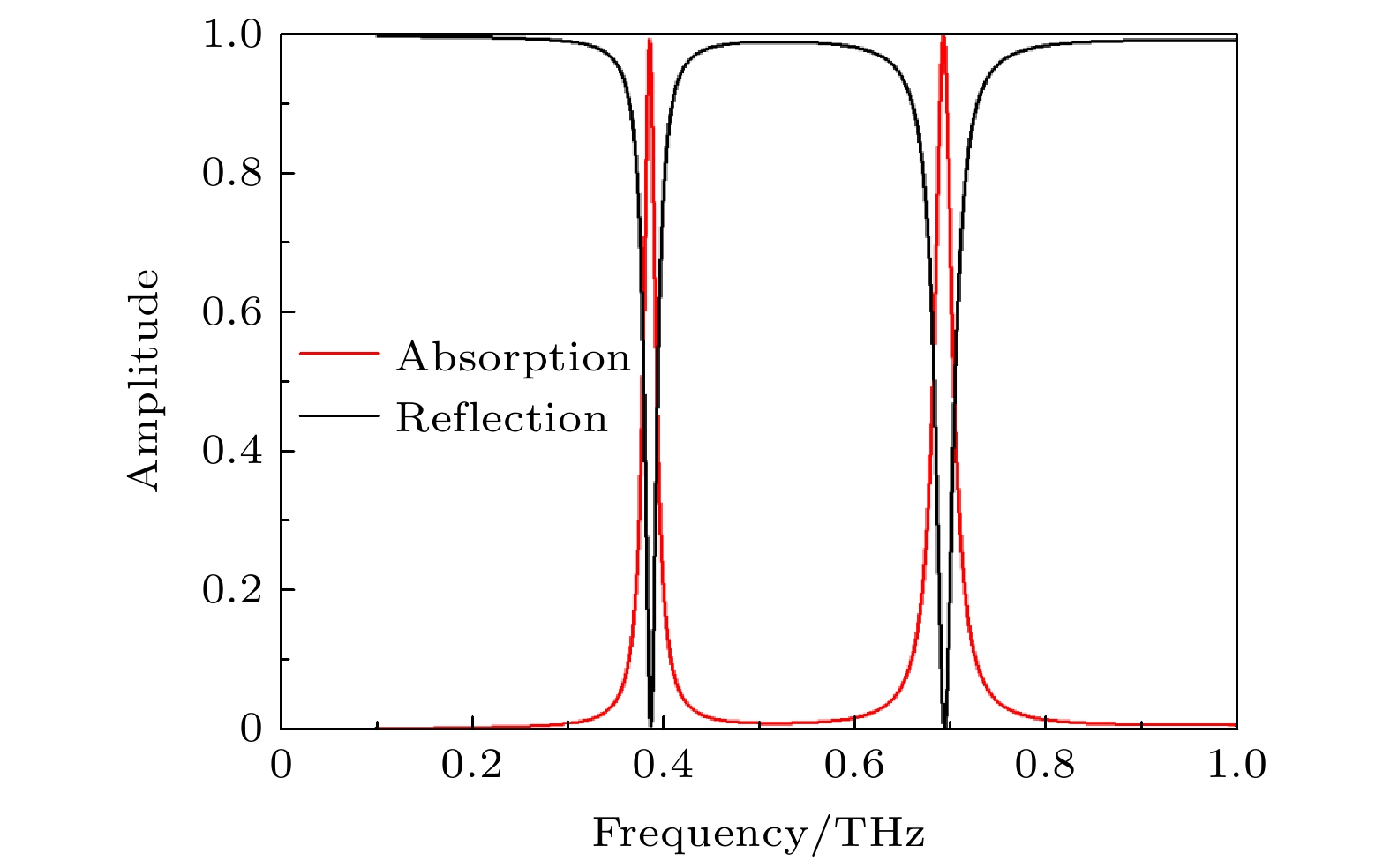 图 2 双频带太赫兹超材料吸波体传感器吸收与反射特性仿真曲线


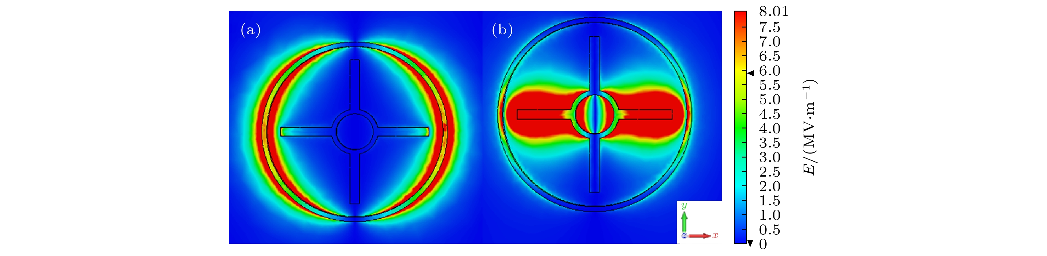 图 3 (a) 谐振频率


 图 4 (a) 谐振频率


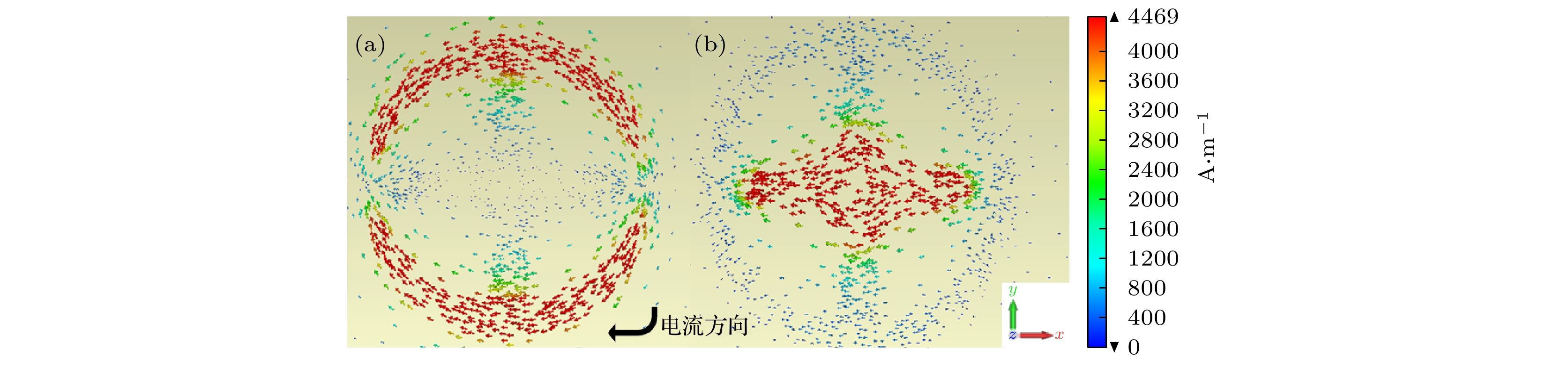 图 5 (a) 谐振频率


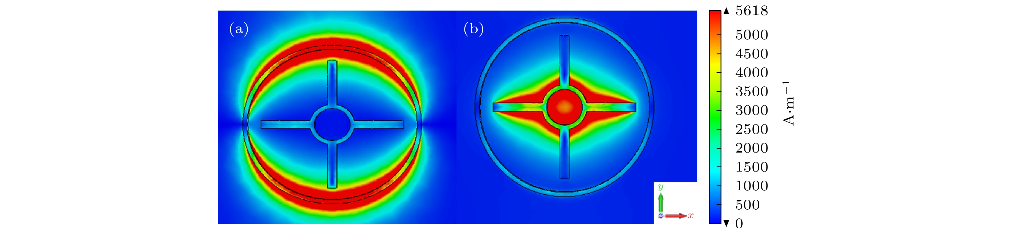 图 6 (a) 谐振频率


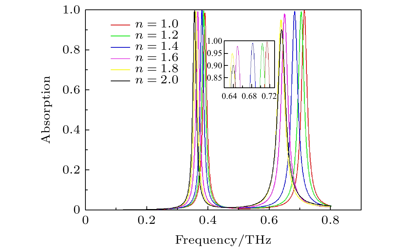 图 7 折射率从


 图 8 待测分析物折射率从


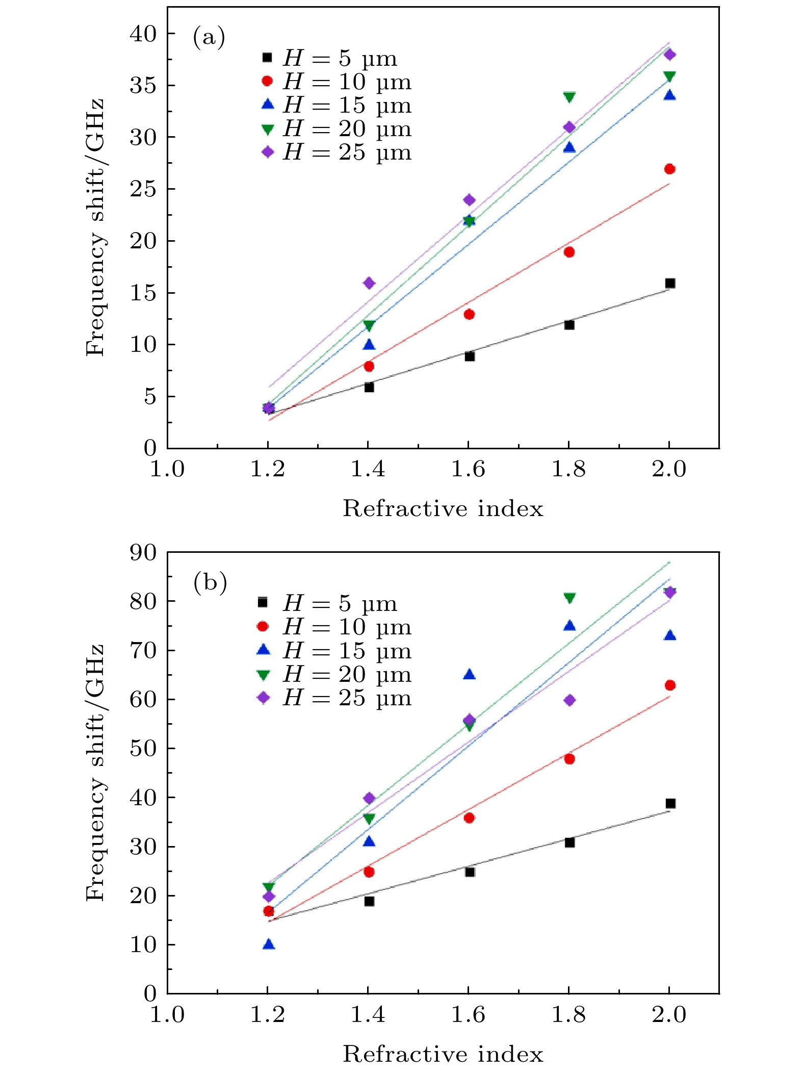 图 9 (a) 待测分析物折射率从


 图 10 待测分析物厚度对传感器折射率频率灵敏度的影响


 图 11 (a) 不同中间介质层材料对传感器谐振频率


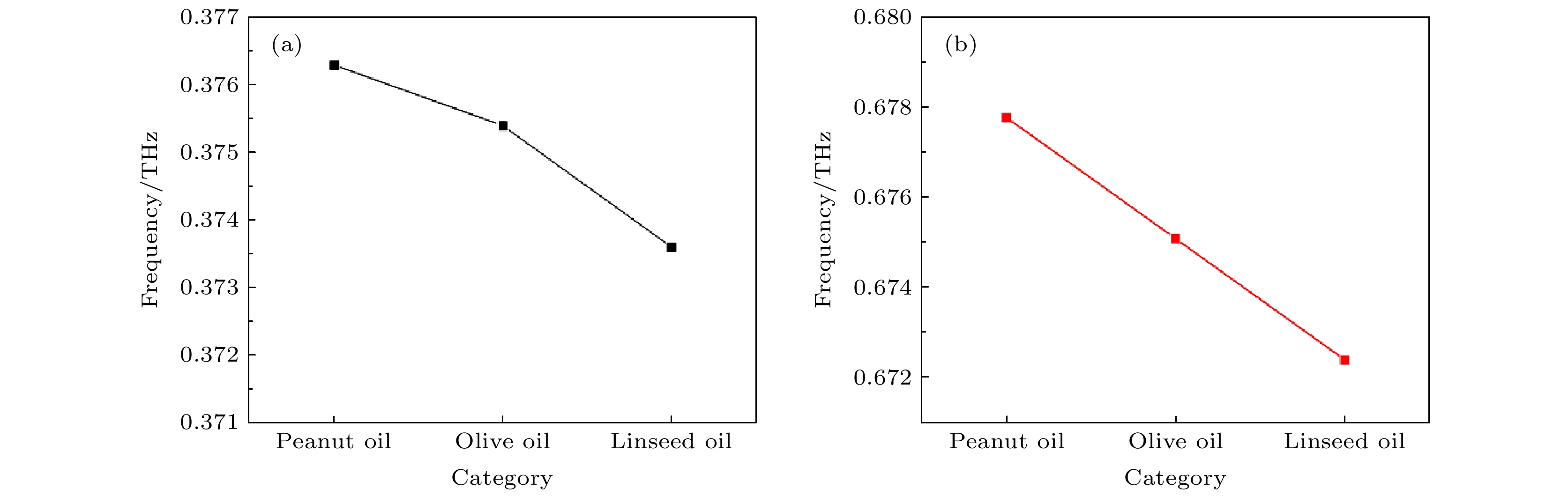 图 12 (a) 传感器检测食用油的谐振频点


