1.State Key Laboratory of Quantum Optics and Quantum Optics Devices, Institute of Laser Spectroscopy, Shanxi University, Taiyuan 030006, China 2.Collaborative Innovation Center of Extreme Optics, Shanxi University, Taiyuan 030006, China
Fund Project:Project supported by the National Key R&D Program of China (Grant No. 2017YFA0304203), the Key Program of the National Natural Science foundation of China (Grant Nos. 61835007, 11434007), the National Natural Science Foundation of China (Grant Nos. 61675123, 61775124, 11804202), the Changjiang Scholars and Innovative Research Team in University of Ministry of Education of China (Grant No. IRT_17R70), and the 1331 Project of Shanxi Province, China.
Received Date:25 August 2020
Accepted Date:27 January 2021
Available Online:02 March 2021
Published Online:20 March 2021
Abstract:We present a high-sensitivity weak microwave measurement and communication technology by employing the Rydberg beat technique. The Rydberg cascade three-level system is composed of a cesium ground state $6{\rm{S}}_{1/2}$, an excited state $6{\rm{P}}_{3/2}$, and a Rydberg state $n{\rm{D}}_{5/2}$ in a room-temperature cesium cell. A two-photon resonant Rydberg electromagnetic induced transparency (EIT) is used to optically detect the Rydberg level, in which a weak probe laser is locked at the resonant transition of $|6{\rm{S}}_{1/2}\rangle \rightarrow |6{\rm{P}}_{3/2}\rangle$, and a strong coupling laser drives the transition of $|6{\rm{P}}_{3/2}\rangle \rightarrow |n{\rm{D}}_{5/2}\rangle$. Both lasers are locked with a high-precision Fabry-Perot cavity. Two E-fields are incident into the vapor cell to interact with Rydberg atoms via a microwave horn, one is a strong microwave field with frequency 2.19 GHz, acting as a local field ($E_{{\rm{L}}}$) and resonantly coupling with two Rydberg energy levels, $|68{\rm{D}}_{5/2}\rangle$ and $|69{\rm{P}}_{3/2}\rangle$, and the other is a weak signal field ($E_{{\rm{S}}}$) with frequency difference ${\text{δ}} f$, interacting with the same Rydberg levels. The wave-absorbing material is placed around the vapor cell to reduce the reflection of microwave field. In the presence of the local field, the Rydberg atoms are employed as a microwave mixer for reading out the difference frequency ${\text{δ}}f$ oscillation signal, which is proportional to the amplitude of weak signal field. The minimum detectable field of $E_{0} = 1.7$ μV/cm is obtained when the lock-in output reaches the base noise. We also measure the frequency resolution of the Rydberg mixer by changing the ${\text{δ}} f$ with fixed $ f_{\rm ref} $, thus achieving a frequency resolution better than 1 Hz. For neighboring fields with 1 Hz away from the signal field, an isolation of 60 dB is achieved. Furthermore, we use the Rydberg atom as an antenna to receive the baseband signals encoded into the weak microwave field, demonstrating that the receiver has a transmission bandwidth of about 200 MHz. The demonstration of sensitivity of Rydberg atoms to microwave field is particularly useful in many areas, such as quantum precise measurement and quantum communications. In general, this technique can be extended to the detection of electromagnetic radiation from the radio-frequency regime to the tera-hertz range and is feasible for fabricating a miniaturized devices, thereby providing us with a way to receive the information encoded in tera-hertz carriers in future work. Keywords:Rydberg atom/ weak electromagnetic field measurement/ communication
全文HTML
--> --> --> 1.引 言无线电波作为现代通信技术的主要载体, 在国防建设、无线通信、生物科学以及新一代5G技术中发挥着极其重要的作用. 其中微波技术更是在雷达探测[1]、气象预测[2]以及无线通信[3]等现代科技领域有着非常广泛的应用, 因此微波探测技术具有重要意义. 传统的微波测量主要基于偶极天线[4-6], 通过微波诱导金属中自由电子产生有规律的感应电流来提取微波电场的信息, 由于自由电子热运动在感应电流中引入随机热噪声, 使经典微波测量方法难以实现超高灵敏度探测. 目前, 传统测量方法主要存在如下技术限制: 1) 预校准; 2) 探头尺寸大, 尤其对于长波长天线喇叭; 3) 带宽小, 对于不同的接收波长需要换用不同的天线; 4)分辨率和灵敏度较低 (1 mV/cm); 5) 测量误差较大(5%—20%), 已不能满足日益发展的科学和技术的需求. 量子测量技术的兴起与发展[7]促进了微波测量技术的进步, 基于Rydberg 原子[8]的微波测量技术受到人们广泛的关注和青睐. Rydberg原子作为一种人造的巨型原子, 具有极大的极化率($ n^{7} $), 相邻能级间隔处于微波波段且具有极大的微波跃迁偶极矩($ n^{2} $), 对外场极为敏感[9]. Rydberg原子作为电磁场传感器, 可实现基于Rydberg原子量子相干效应的全光学[10-12] 的外场测量. 2007 年, Adams小组[13]首次在Rydberg原子中观察到电磁感应透明(EIT)效应, 实现了Rydberg原子的光学探测. 2012年, Shaffer小组[14]首次在实验上利用微波耦合相邻Rydberg能级产生的Autler-Townes (AT)分裂[15-18], 实现了基于Rydberg原子的微波弱场测量, 测量的最小值达8 μV/cm, 测量灵敏度为30 μV/cm/Hz. 随后, 他们通过改进实验技术, 利用马赫-曾德尔干涉仪和零差探测技术将测量灵敏度达提高到5 μV/cm/Hz [19], 并且提出光子散粒噪声是限制测量灵敏度进一步提高的主要原因. 利用Rydberg原子还可实现微波场极化方向[20,21]和静态电场[22]的测量, 以及高分辨率微波成像[23]等. 上述基于Rydberg原子EIT-AT效应的微波测量是通过测量AT分裂间隔得到微波场的强度, 测量的有效范围受到EIT谱线线宽的限制. 在冷原子中获得窄线宽的EIT谱线, 可实现100 μV/cm的最小测量值[24]. 为了突破EIT谱线线宽的限制, 近年来, 人们发展了基于Rydberg原子的拍频测量技术[25-27], 根据拍频信号的大小读出待测场的强度, 实现了微波测量极限的突破, 可实时测量的最小值达到0.4 μV/cm, 通过积分测量达到780 pV/cm. 同时, 人们也发展了基于Rydberg原子的微波通信技术, 将Rydberg原子作为微波接收天线, 通过调制技术将基带信号编码到微波中, 实现了Rydberg原子对基带信号的实时读出. 2018年, 首次报道了利用Rydberg原子的EIT-AT效应, 演示了调幅微波场的通信, 实现了1 MHz基带信号场的传输[28]. 随后, 人们对其数据的传输能力[29]、信号保真度和动态响应范围[30]以及微波载波的带宽[31]等进行了研究, 最近相继报道了基于Rydberg原子的调频[32]、调相[33]等多种通信方式. 上述的报道都是基于Rydberg原子EIT-AT效应进行的通信技术, 所需载波场功率较大, 在实际应用中受到一定的限制. 本文以2.19 GHz的微波场耦合 $|68 {\rm{D}}_{5/2}\rangle \rightarrow $$ |69 {\rm{P}}_{3/2}\rangle$的跃迁为例, 利用Rydberg原子阶梯型三能级EIT光学探测方法, 研究了基于Rydberg原子拍频技术的微弱场测量和通信. 采用Rydberg原子作为微波混频器, 测量了不同信号场强度下, 拍频信号幅值的变化以及频率分辨率, 最小测量值为$E_{0} = 1.7\; {\rm{{\text {μ}} V/cm}}$, 频率分辨率小于1 Hz. 并将此方法用于通信, 实现了音频信号的传输和读取, 测量的传输带宽可达200 MHz. 本文的研究对于电磁场的量子精密测量和通信具有重要的意义. 2.实验装置基于铯Rydberg原子的拍频方法实现微弱场的测量和通信的实验装置和相关的跃迁能级如图1(a)和图1(b)所示. 一束852 nm (Toptica, DL Pro)的探测光$\lambda_{{\rm{p}}}$以及一束510 nm (Toptica, DLpro + Precilasers YFL-SHG-509-1.5)的耦合光$\lambda_{{\rm{c}}}$相向作用于铯原子蒸气池中, 其中探测光共振激发$|6 {\rm{S}}_{1/2}, $$ (F = 4)\rangle \rightarrow |6 {\rm{P}}_{3/2}, (F' = 5)\rangle$的跃迁, 耦合光作用于$|6 {\rm{P}}_{3/2}, (F' = 5)\rangle \rightarrow |68 {\rm{D}}_{5/2}\rangle$ 的跃迁, 形成阶梯型Rydberg EIT系统, 由EIT信号实现对Rydberg原子的光学探测. 频率为2.19 GHz的微波场作为本地场$(E_{{\rm{L}}})$, 共振耦合相邻的两个Rydberg 态$|68 {\rm{D}}_{5/2}\rangle \rightarrow |69 {\rm{P}}_{3/2}\rangle$, 产生EIT-AT分裂; 另一具有一定频率失谐$ {\text{δ}} f$的待测微弱信号场$(E_{{\rm{S}}})$与本地场合束后输入到微波喇叭中, 沿垂直于激光传播的方向入射作用于原子蒸气池中. Rydberg EIT可直接读出频率为$ {\text{δ}} f $的拍频信号, 将拍频信号输入到锁相放大器并与同频的参考信号$f_{{\rm{ref}}}$进行解调实现待测信号的测量. 实验中激光的偏振和微波的偏振方向保持一致. 对于实现弱场条件的通信, 将待传输的基带信号通过传统的调制技术加载到微弱信号场中. 另外, 为了减少激光功率波动对微弱场测量造成的影响, 作用一束不与耦合光重合的参考光, 该参考激光经过铯原子蒸气池后与探测光一起进入差分探测器. 为了减少因光学元器件对微波反射引起的测量误差, 将SA泡沫角锥吸波材料置于蒸气池的周围, 如图1(a)所示. 在展示通信的实验中, 将基带信号通过振幅调制技术加载到弱信号场作为载波, 由Rydberg原子实现传输信号的直接读出. 图 1 (a) 实验装置图. $\lambda_{{\rm{p}}}$ = 852 nm的探测光与$\lambda_{{\rm{c}}}$ = 510 nm的耦合光相向作用于铯原子蒸气池中, 两束激光偏振相同. 探测光经偏振分光棱镜(PBS)分为两束, 一束与耦合光重合形成EIT, 另一束作为背景光通过蒸气池, 两束光经样品池后进入平衡零拍探测器(PDB), 以减小由于功率起伏引起的噪声. 较强的本地场$(E_{{\rm{L}}})$与待测信号场$(E_{{\rm{S}}})$合束后通过微波喇叭出射作用于铯原子. 吸波材料(WAM)置于蒸气池周围以减少由光学元件引起微波反射而产生的测量误差. 当此装置用于通信信号的传输时, 将基带信号由幅度调制方式加载到弱信号场. (b) 四能级原子示意图. 探测光$\lambda_{\rm p}$共振作用于铯原子基态$|6 {\rm{S}}_{1/2}\rangle$至激发态$|6 {\rm{P}}_{3/2}\rangle$的跃迁. 耦合光$\lambda_{\rm{c}}$ 作用于$|6 {\rm{P}}_{3/2}\rangle \rightarrow |68 {\rm{D}}_{5/2}\rangle$的Rydberg跃迁. 本地场$(E_{{\rm{L}}})$共振耦合相邻的Rydberg能级$|68 {\rm{D}}_{5/2}\rangle$与$|69 {\rm{P}}_{3/2}\rangle$, 待测弱场$(E_{{\rm{S}}})$与本地场相差频率${\text{δ}} f$ Figure1. (a) Sketch of the experimental setup. A probe laser, $\lambda_{{\rm{p}}}$ = 852 nm, and a coupling laser, $\lambda_{{\rm{c}}}$ = 510 nm, are counter-propagated through a cesium room-temperature cell with same polarization. An 852 nm laser is separated into two with a PBS, one is counter-propagated with the coupling laser forming EIT, while the other passes through the vapor cell as a reference beam. Both are detected with a PDB to reduce the background noise caused by laser power fluctuation. A strong local field $(E_{{\rm{L}}})$ and the weak signal field $(E_{{\rm{S}}})$ are combined by a power combiner and coupled to free space to interact with Rydberg atoms via a microwave horn. The WAM is placed around the vapor cell to reduce reflection of microwave field. The baseband signal is encoded into the weak signal field with amplitude modulation when communication signals are transferred. PBS, polarizing beam splitter; PDB, balanced amplified photo-detectors; WAM, wave-absorbing material. (b) Diagram of four-level scheme. A probe laser is resonant with the ground transition, $|6 {\rm{S}}_{1/2}\rangle$$\rightarrow$$|6 {\rm{P}}_{3/2}\rangle$, and the coupling laser drives the Rydberg transition, $|6 {\rm{P}}_{3/2}\rangle \rightarrow |68 {\rm{D}}_{5/2}\rangle$. The local field $(E_{{\rm{L}}})$ is resonant with two Rydberg levels $|68 {\rm{D}}_{5/2}\rangle$ and $|69 {\rm{P}}_{3/2}\rangle$, the weak signal field $(E_{{\rm{S}}})$ has frequency difference ${\text{δ}} f$ with local field
其中$\Delta\omega = \omega_{{\rm{L}}}-\omega_{{\rm{S}}}\ll\overline{\omega} = (\omega_{{\rm{L}}}+\omega_{{\rm{S}}})/2$, $\Delta\phi = \phi_{\rm L}- $$ \phi_{\rm S}$. 实验中, 两微波场频率相差${\text{δ}} f$ = $ \Delta\omega $/$ 2\pi $ = 50 kHz. 利用10 MHz 铷原子钟同步两微波源. (4)式表明, 原子感受到的电场强度与信号场强度成正比, 并且产生${\text{δ}} f$的差频调制. 实验上, 首先利用EIT-AT光谱对微波源进行校对, 测量的EIT-AT分裂与微波源的输出功率$ \sqrt{P} $成正比, 如图2中的黑色正方形所示. 实线表示理论计算的微波电场在铯原子气室处的电场强度, 计算公式为 图 2 测量的微波场强与信号源输出功率的依赖关系, 黑色方点表示EIT-AT分裂测量的结果, 蓝色圆点表示拍频测量的结果. 黑色实线表示由(5)式计算的电场值与微波输出功率的关系, 与实验测量相符. 最小测量电场为$E_{0}=1.7$ μV/cm, 如图中红色阴影圈所示 Figure2. Microwave field measurements as a function of square root of the output power. The black squares show EIT-AT measurements and blue circles for beat method. The black solid line shows the calculation of Eq. (5). The measurable minimum field is $E_{0}=1.7$ μV/cm, as shown with the red shadow circle
$ \begin{array}{l} E = \dfrac{\sqrt{30P\cdot g}}{d}, \end{array} $
其中, g为增益系数, d为微波喇叭与铯原子蒸气池中心的距离. 由图2可知, 在微波场强较大时, 实验测量与理论计算相一致. 黑色线提供了电场校准值. 当信号场减小到(1)式不再适用时, 利用上述的拍频法测量弱信号的强度, 典型的测量结果如图2中的蓝色圆圈所示, 测量结果与(4)式中描述的线性关系相一致. 将测量点对应的微波源输出功率与黑色的理论计算相对应, 即可得出测量的电场值. 实验获得的最小测量值为$E_{0} = $$ 1.7$ μV/cm. 由此可知拍频法极大地提高了微波测量的精度, 比传统的测量方法提高了3个数量级. 为进一步了解拍频测量技术, 本文通过改变触发锁相放大器的参考频率$f_{{\rm{ref}}}$研究基于Rydberg原子的拍频方法的隔离特性和频率分辨率. 实验上设置锁相放大器的时间参数为1 s, 对应的频率截点为1 Hz, 选取信号场与本地场的频率差${\text{δ}} f$ = 50 kHz, 弱场场强$E_{1} = 1.7$ μV/cm 作为电场强度的归一化值. 当解调信号频率$f_{{\rm{ref}}}$与差频信号${\text{δ}} f$ 同频时, 将锁相放大器在此时输出的电平值作为基准, 标为输出电平的0 dB. 设置$f_{{\rm{ref}}}$与${\text{δ}} f$的频率差分别为 0.1, 0.5, 1, 10 Hz, 测量不同微波场功率对应的输出电平信号, 图3 所示为实验测量结果. 以1 Hz的频差(蓝色三角形)的结果为例进行分析, 由图3可知, 对于1 Hz的频差, 输出信号的幅值降到–3 dB时, 电场强度比同频时的电场强度高出60 dB, 即可以实现60 dB的信号隔离. 同理, 0.5 Hz的频差可以实现40 dB 信号的隔离. 由图3可知, 拍频法微波测量技术可实现亚赫兹的频率分辨, 最小的频率分辨率达0.1 Hz. 图 3 拍频的隔离特性和频率分辨率测量. 设置时间常数为1 s, 分别$f_{{\rm{ref}}}$与${\text{δ}} f$的频率差为 0.1, 0.5, 1, 10 Hz时, 测量锁相放大器的输出电平信号. 1 Hz的频差对应60 dB的隔离, 0.5 Hz的频差可以实现40 dB信号的隔离. 拍频微波测量技术可实现亚赫兹的频率分辨, 最小的频率分辨率达0.1 Hz. 灰色阴影部分表示基底噪声信号, 约为–15 dB Figure3. Measurements of the isolation and frequency resolution. The lock-in output levels are obtained with the time constant 1 s and the difference of $f_{{\rm{ref}}}$ and ${\text{δ}} f$ are 0.1, 0.5, 1, and 10 Hz, respectively. The frequency difference of 1 Hz (0.5 Hz) corresponds to the isolation of 60 dB (40 dB). The beat frequency microwave measurement can realize the frequency resolution of sub-Hz, with the minimum frequency resolution up to 0.1 Hz. The grey area around –15 dB is base noise
23.2.微波通信 -->
3.2.微波通信
目前, 文献报道的基于Rydberg原子的通信方案是基于共振EIT-AT光谱, 对应的载波场较强[30]. 在利用拍频技术实现微弱场测量的基础上, 本文提出将基带信号加载到信号场上, 从而实现微弱场条件下的微波通信. 通过幅度调制技术将基带信号加载到信号场中, Rydberg原子作为解调器可以直接将加载的信息提取出来. 图4(a)给出了基于Rydberg原子拍频技术的音频信号的传输和读取, 对应的载波场强为160 μV/cm. 黑色实线为传输的音频信号, 红色虚线为由Rydberg原子提取的音频信号, 很好地实现了弱场条件下信息的传输和读取. 图4(b)为加载到信号场中的频率为1 kHz的调制信号, 图4(c)为信号场强度为50 μV/cm, 信号微波场失谐量分别为30, 0和–15 MHz时, 读出的1 kHz基带调制信号. 可以看出, 在微弱载波场(50 μV/cm)时, Rydberg原子天线仍可实现基带信号的实时读取. 当微波场失谐不同时, 对应提取信号的相位不同, 由此可以进一步利用调制相位的方法进行信息的传输. 图 4 (a)基于Rydberg原子拍频技术实现的音频信号的传输与提取. 将音频信号加载到弱信号场(160 μV/cm)上, Rydberg原子实现了信号的直接提取. 黑色实线表示传输的音频信号, 红色线表示Rydberg原子直接读取的音频信号. (b) 传输的调制频率为1 kHz的基带信号. (c) 在信号场为50 μV/cm时, 微波场失谐$\varDelta_{{\rm{RF}}}/2{\text{π}}$ 分别为30, 0, –15 MHz 时的Rydberg 原子读出的信号 Figure4. (a) Demonstration of transfer and readout of the baseband signal based on Rydberg beat method. The audio signal is amplitude modulated into the weak carrier field of 160 μV/cm, Rydberg atoms are used to readout the transferred audio signal. The top line represents the original transferred signal, and the bottom line displays the retrieved signal. (b) A 1 kHz baseband signal is encoded into the weak carrier field (50 μV/cm) with the amplitude modulation method. (c) The retrieved baseband signals based on Rydberg atoms for $\varDelta_{{\rm{RF}}}/2{\text{π}}$ = 30, 0, –15 MHz, respectively
在实际应用中, 信号的传输带宽是非常重要的参数, 因此对拍频技术的传输带宽进行了测量. 由图4可以看出, 当频率失谐增大时读出的信号强度减小, 50 μV/cm的弱载波场条件下的传输带宽约为50 MHz. 为了研究基于拍频技术的传输带宽, 在较强的信号场下作了进一步的测量. 图5所示为${\text{δ}} f = 50\; {\rm {kHz}}$, 本地场强度为$ E_{0} $ = 3.9 mV/cm, 信号场强度为$ E_{0} $ = 1.7 mV/cm 时, 改变信号微波场失谐所提取的拍频信号的强度. 当微波场失谐为150 MHz时电平最小, 对应的调谐带宽大于200 MHz. 图 5 传输带宽的测量. 改变信号微波场失谐, 测得不同失谐时的电平信号, 以电平最低(即$\Delta_{RF}/2\pi = 150$ MHz)为零点归一化, 实现了调谐带宽大于200 MHz. 其中本地场强度为$E_{0} = 3.9$mV/cm, 信号场强度为$E_{0}=1.7$mV/cm Figure5. Measurements of bandwidth. The obtained transmission bandwidth is larger than 200 MHz. Lock-in signal is normalized by minimum level ($\varDelta_{\rm RF}/2\pi = 150$ MHz). The Local field strength is $E_{0}$ = 3.9 mV/cm and the signal field strength is $E_{0}$ = 1.7 mV/cm


 图 1 (a) 实验装置图.


 图 2 测量的微波场强与信号源输出功率的依赖关系, 黑色方点表示EIT-AT分裂测量的结果, 蓝色圆点表示拍频测量的结果. 黑色实线表示由(5)式计算的电场值与微波输出功率的关系, 与实验测量相符. 最小测量电场为


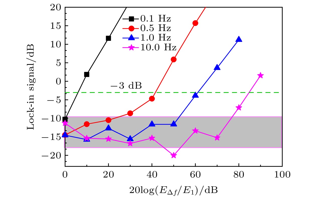 图 3 拍频的隔离特性和频率分辨率测量. 设置时间常数为1 s, 分别


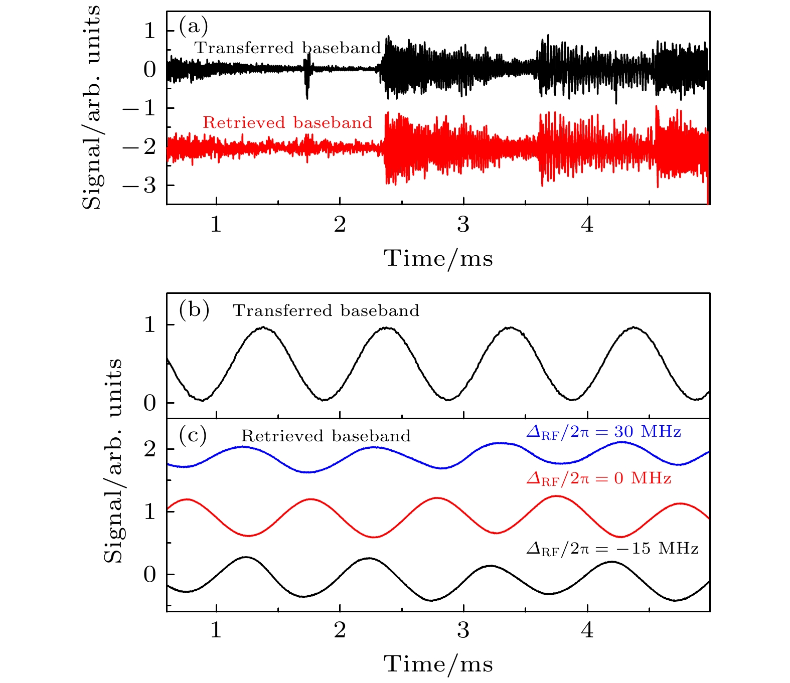 图 4 (a)基于Rydberg原子拍频技术实现的音频信号的传输与提取. 将音频信号加载到弱信号场(160 μV/cm)上, Rydberg原子实现了信号的直接提取. 黑色实线表示传输的音频信号, 红色线表示Rydberg原子直接读取的音频信号. (b) 传输的调制频率为1 kHz的基带信号. (c) 在信号场为50 μV/cm时, 微波场失谐


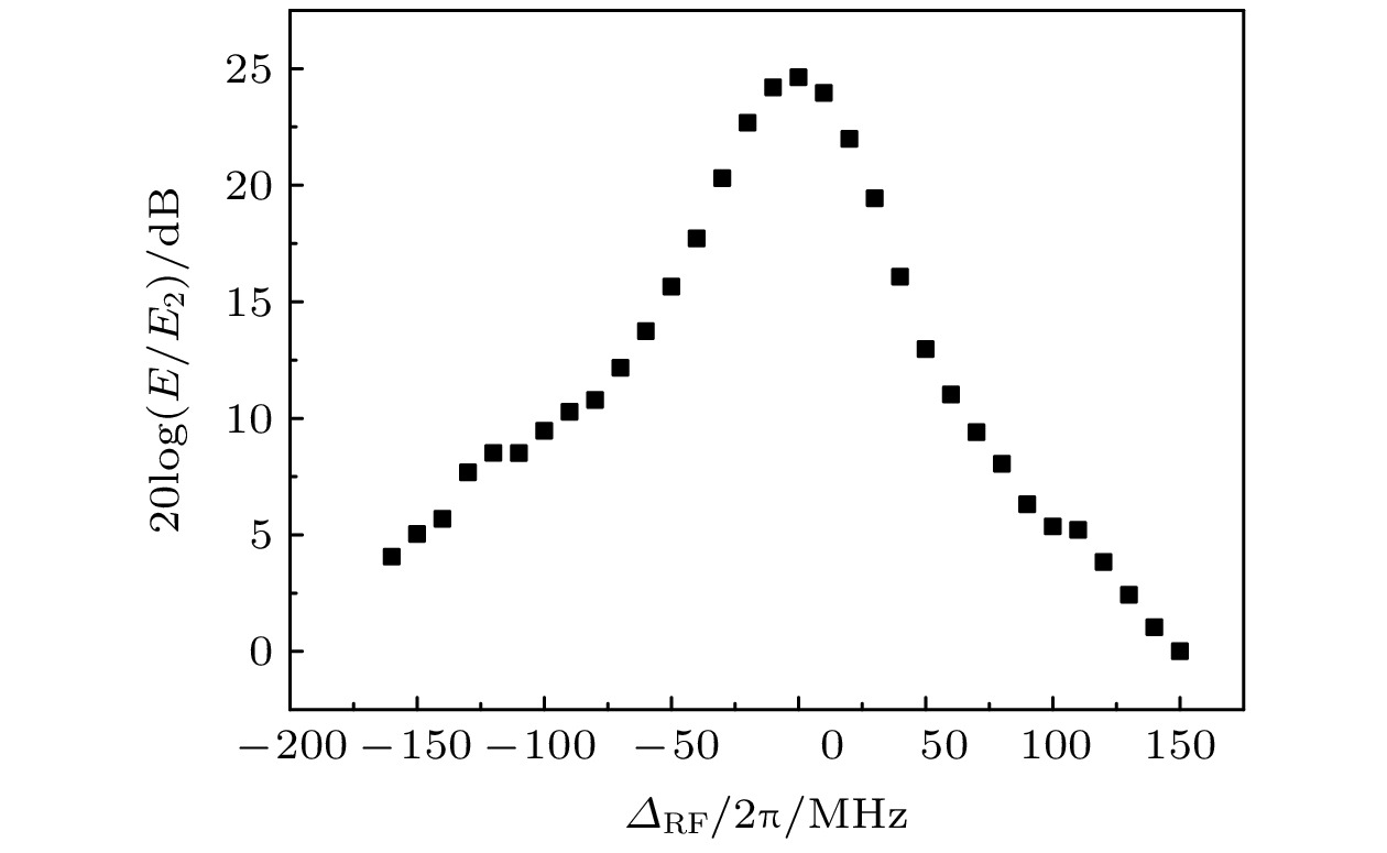 图 5 传输带宽的测量. 改变信号微波场失谐, 测得不同失谐时的电平信号, 以电平最低(即


