State Key Laboratory of Complex Electromagnetic Environment Effects on Electronics and Information System, National University of Defense Technology, Changsha 410073, China
Fund Project:Project supported by the National Natural Science Foundation of China (Grant Nos. 61701507, 61890542, 61890540)
Received Date:13 July 2020
Accepted Date:28 August 2020
Available Online:09 February 2021
Published Online:20 February 2021
Abstract:In this paper, a new designed bistatic electromagnetic vector sensors multiple-input multiple-output radar with long dipoles and large loops is proposed to avoid the low inefficient electromagnetically radiation efficiency of original bistatic electromagnetic vector sensors multiple-input multiple-output radar with short dipoles $\left(({L}/{\lambda }) < 0.1\right)$ and small loops $\left(2\pi ({R}/{\lambda }) < 0.1\right)$. The new transmitting and receiving sensors are designed based on the effective length of the electromagnetic vector sensor in practical engineering application. Firstly, the Parallel Factor trilinear alternating least square algorithm is proposed to make full use of the spatial-temporal tensor model for received data after matching filtering. And, the closed-form automatically paired two dimensional Direction of Departure and two dimensional Direction of Arrival can be obtained with the aid of the Parallel Factor trilinear alternating least square algorithm. Furthermore, due to the vector-cross-product Poynting-vector algorithm is failed in the condition of the new designed electromagnetic vector sensors with long dipoles and large loops, an efficient blind estimation method without requiring the prior knowledge of the dipoles’ electric length ${L}/{\lambda }$ and loops’ electric radius ${R}/{\lambda }$ is detailed derived to deal with the estimation of the transmitting azimuth angle, transmitting polarization angle, transmitting polarization phase difference, receiving azimuth angle, receiving polarization angle and receiving polarization phase difference. And, the estimated transmitting azimuth angle, transmitting polarization angle, transmitting polarization phase difference, receiving azimuth angle, receiving polarization angle and receiving polarization phase difference are also automatically paired without additional angle parameter pair matching process. Finally, the expression of the Cramer Rao Bound is detailed derived for the designed new bistatic electromagnetic vector sensors multiple-input multiple-output radar. The detailed derived Cramer Rao Bound can provide a benchmark for angle parameter and polarization parameter estimation performance. Additionally, simulation results are conducted to verify the better angle parameter and polarization parameter estimation accuracy of the proposed method for the new designed bistatic electromagnetic vector sensors multiple-input multiple-output radar with long dipoles and large loops. Through theoretical analysis and simulation results, it is can be founded that the length of the electric dipole and the circumference of the loops should be suitable selected to guarantee a better estimation accuracy. Thus, the interesting work in this paper can further promote the engineering application of electromagnetic vector sensor in bistatic multiple-input multiple-output radar. Keywords:long dipoles/ large loops/ bistatic multiple-input multiple-output radar/ parallel factor method/ blind estimation method/ joint angle and polarization estimation
如图1所示, 电磁矢量传感器包含三个相互正交的电偶极子和三个相互正交的磁环, 其中三个正交的电偶极子和磁环分别被用来实现对电场矢量和磁场矢量的测量. 图 1 三正交电偶极子和三正交磁环示意图 Figure1. Three orthogonal dipoles and three orthogonal loops.
如图2所示, 考虑一个包含M个长电偶极子和大磁圆环组成的新型EMVS 发射阵列和N个长电偶极子和大磁圆环组成的新型EMVS 接收阵列的双基地 EMVS-MIMO 雷达系统, 其中发射阵列和接收阵列的阵元间距均是半波长. 且发射EMVS阵列和接收EMVS阵列中长电偶极子的长度和大磁环的周长分别设置为$L\;\left(({L}/{\lambda }) > 0.1\right)$和$R\;\left(2{\text{π}}({R}/{\lambda }) > 0.1\right)$. 因此, 新型发射EMVS阵列和新型接收EMVS阵列的阵元位置为 图 2 长电偶极子和大磁圆环组成的新型双基地EMVS-MIMO雷达系统示意图 Figure2. New designed bistatic EMVS-MIMO radar system with long dipoles and large loops.
图 4 新型双基地EMVS-MIMO雷达角度参数和极化参数估计星座图 (a) 发射俯仰角和接收俯仰角; (b) 发射方位角和接收方位角; (c) 发射俯仰角和发射方位角; (d) 发射极化角和极化相位差; (e) 接收俯仰角和接收方位角; (f) 接收极化角和极化相位差 Figure4. Scatter plot of the angle parameters and polarization parameters by using the new designed bistatic EMVS-MIMO radar: (a) Scatter plot of the transmit elevation angle and receive elevation angle ; (b) scatter plot of the transmit azimuth angle and receive azimuth angle; (c) scatter plot of the transmit elevation angle and azimuth angle ; (d) scatter plot of the transmit polarization angle and polarization phase difference; (e) scatter plot of the receive elevation angle and azimuth angle ; (f) scatter plot of the receive polarization angle and polarization phase difference.
在第二个仿真实验中, 验证长电偶极子和大磁圆环组成的新型EMVS阵列的角度和极化参数估计性能随信噪比的变化. 均方误差的定义为${\rm RMSE} = \sqrt {\displaystyle\frac{1}{{KI}}\sum\limits_{i = 1}^I {{{\left\| {\tilde \vartheta - \vartheta } \right\|}^2}} }$, 其中$\tilde \vartheta $表示估计得到的角度或极化参数, $\vartheta $表示真实的角度或极化参数, I表示蒙特卡罗仿真实验次数. 在这个仿真中, 信噪比的变化范围是$ - 10$—$30\;{\rm{dB}}$, 变化的步长为$5\;{\rm{dB}}$, 在每个信噪比条件下蒙特卡罗仿真实验次数为200. 同时, 也给出了相应的检测成功概率曲线. 其中检测成功概率定义为每个入射信源的估计角度和极化角度与真实的角度和极化角度的差值小于${1^ \circ }$. 入射信源的个数K 此时设置为3, 相应的发射四维参数和接收四维参数和第一个实验中前三个入射信源相同. 长电偶极子的长度设置为${L}/{\lambda } = 0.5$, 大磁圆环的周长设置为$2{\text{π}}({R}/{\lambda }) = 1$. 其中的下标d表示角度参数, 下标p表示极化参数. 图中${s_{{\rm{1 d}}}}$, ${s_{{\rm{2 d}}}}$, ${s_{{\rm{3 d}}}}$和${{\rm CRB}_{\rm{d}}}s1$, ${{\rm CRB}_{\rm{d}}}s2$, ${{\rm CRB}_{\rm{d}}}s3$ 分别对应于第一个信源、第二个信源和第三个信源的角度参数以及相应的克拉美罗界. 同样地, 图中${s_{1{\rm{p}}}}$, ${s_{2{\rm{p}}}}$, ${s_{{\rm{3 p}}}}$, 和${{\rm CRB}_{\rm{p}}}s1$, ${{\rm CRB}_{\rm{p}}}s2$, ${{\rm CRB}_{\rm{p}}}s3$ 分别对应于第一个信源、第二个信源和第三个信源的极化参数以及相应的克拉美罗界. 从图5中可以看出, 每个信源的均方误差性能和检测成功概率随着信噪比的增加而提升. 通过仿真可以发现, 对于实际中用到的长电偶极子和大磁环组成的EMVS双基地MIMO雷达系统, 通过对电偶极子和磁环周长进行合理的设置, 其相应的角度参数估计精度能够维持在一个合理的区间. 总体上, 在信噪比大于$10\;{\rm{dB}}$ 之后, 所提出的盲估计算法具有较好的参数估计精度. 因此, 图5中的仿真实验结果为进一步利用长电偶极子和大磁圆环组成的新型EMVS阵列提供了相应的指导. 图 5 新型阵列角度和极化参数估计性能随信噪比的变化 (a) 角度估计均方误差随信噪比的变化; (b) 角度检测概率随信噪比的变化; (c) 极化估计均方误差随信噪比的变化; (d) 极化检测概率随信噪比的变化 Figure5. The effect of the SNR for the proposed new bistatic EMVS-MIMO radar: (a) Curves of angle’s RMSE versus SNR; (b) curves of angle’s PSD versus SNR; (c) curves of polarization’s RMSE versus SNR; (d) curves of polarization’s PSD versus SNR.
24.3.长电偶极子和大磁圆环组成的新型EMVS阵列随快拍数的变化 -->
4.3.长电偶极子和大磁圆环组成的新型EMVS阵列随快拍数的变化
在第三个实验中考虑快拍数对长电偶极子和大磁圆环组成的双基地EMVS-MIMO雷达角度参数估计性能的影响. 这里, 入射信源的个数以及其相应的发射和接收四维参数和第二个实验相同. 长偶极子的长度和大圆环的周长仍然保持不变. 快拍数的变化范围为$100 - 1000$, 变化的步长为100. 信噪比设置为$10\;{\rm{dB}}$. 在每个快拍数条件下蒙特卡罗仿真实验次数为200. 从图6中的仿真结果可以看出, 随着快拍数的增加, 新型EMVS阵列的角度和极化参数估计性能在提升. 但是由于信噪比设置为$10\;{\rm{dB}}$, 三个信源最终的检测成功概率仍然不能接近于1. 这说明在该信噪比的条件下, 利用新型阵列结构估计得到的角度参数和极化参数和真实的角度参数和极化参数之间的差值仍然大于所设定的门限值. 因此, 为了获得更加良好的角度和极化参数性能, 在实际的角度参数估计中, 应该设置较高的信噪比门限, 从而提升新型阵列的空间目标获取能力. 图 6 新型阵列角度和极化参数估计性能随快拍数的变化 (a) 角度估计均方误差随快拍数的变化; (b) 角度检测概率随快拍数的变化; (c) 极化估计均方误差随快拍数的变化; (d) 极化检测概率随快拍数的变化 Figure6. The effect of the snapshot for the proposed new bistatic EMVS-MIMO radar: (a) Curves of angle’s RMSE versus snapshot; (b) curves of angle’s PSD versus snapshot; (c) curves of polarization’s RMSE versus snapshot; (d) curves of polarization’s PSD versus snapshot.
24.4.电偶极子的长度对估计精度的影响 -->
4.4.电偶极子的长度对估计精度的影响
在第四个仿真实验中验证电偶极子的长度变化对双基地EMVS-MIMO雷达中角度和极化参数估计性能的影响, 该仿真实验结果为设计合适长度的电偶极子提供相应的参考. 入射信源的个数及其发射四维参数和接收四维参数和第二个实验相同. 此时, 信噪比和快拍数分别被设置为200和$10\;{\rm{dB}}$. 大磁环的周长被设置为$2{\text{π}}({R}/{\lambda }) = 1$. 电偶极子的长度的变换范围是0.1—0.8, 变化步长为0.1. 在每个大电偶极子背景下蒙特卡罗仿真实验次数被设置为200. 从图7中的仿真结果可以发现, 随着电偶极子长度的增加, 所设计的新型EMVS-MIMO雷达的角度参数和极化参数估计性能先是变好, 然后又变差. 这说明并不是电偶极子的长度越长越好, 越长的电偶极子可能会产生较大的角度和极化参数估计误差. 同时从检测成功概率曲线可以看出, 随着电偶极子长度的增加, 对于极化参数具有较低的估计性能. 该仿真实验说明在此信噪比和快拍数的背景下, 长电偶极子的长度变化对极化参数的估计能力较弱. 图 7 不同电偶极子的长度对角度和极化参数估计性能的影响 (a) 角度估计均方误差随电偶极子长度的变化; (b) 角度检测概率随电偶极子长度的变化; (c) 极化估计均方误差随电偶极子长度的变化; (d) 极化检测概率随电偶极子长度的变化 Figure7. The effect of the various ${L}/{\lambda }$ for the proposed new bistatic EMVS-MIMO radar: (a) Curves of angle’s RMSE versus various ${L}/{\lambda }$; (b) curves of angle’s PSD versus various ${L}/{\lambda }$; (c) curves of polarization’s RMSE versus various ${L}/{\lambda }$; (d) curves of polarization’s PSD versus various ${L}/{\lambda }$.
24.5.磁偶极子的周长对估计精度的影响 -->
4.5.磁偶极子的周长对估计精度的影响
最后, 通过仿真实验来验证磁偶极子的周长对新型阵列角度和极化参数估计性能的影响. 入射信源的个数及其发射四维参数和接收四维参数和第二个实验相同. 此时, 信噪比和快拍数分别被设置为200和$10\;{\rm{dB}}$. 长电偶极子的长度被设置为${L}/{\lambda } = 0.5$. 大磁环周长的变换范围是0.1—2.8, 变化步长为0.3. 在每个大磁环周长背景下蒙特卡罗仿真实验次数被设置为200. 从图8的仿真结果可以发现, 随着磁偶极子周长的增加, 所设计的新型EMVS-MIMO雷达的角度参数和极化参数估计性能并不能一直保持不变. 当磁环的周长$2{\text{π}}({R}/{\lambda }) > 1$时, 新型EMVS阵列的角度参数和极化参数估计性能随着磁环周长的增加而变差. 对应的检测成功概率也较差. 尤其是对于极化参数的估计性能, 其均方误差还是具有相对较大的值. 因此, 在对磁环周长进行设计时, 不能一味地追求辐射效率而忽视角度参数估计精度. 通过第四个和第五个实验, 在进行长电偶极长度和大磁环周长设计时, 即要兼顾辐射效率也要兼顾角度参数估计精度, 在二者之间寻求一个较好的平衡点. 图 8 不同磁偶极子周长对角度参数和极化参数估计性能的影响 (a) 角度估计均方误差随磁偶极子周长的变化; (b) 角度检测概率随磁偶极子周长的变化; (c) 极化估计均方误差随磁偶极子周长的变化; (d) 极化检测概率随磁偶极子周长的变化 Figure8. The effect of the various $2{\text{π}}({R}/{\lambda })$ for the proposed new bistatic EMVS-MIMO radar: (a) Curves of angle’s RMSE versus various $2{\text{π}}({R}/{\lambda })$; (b) curves of angle’s PSD versus various $2{\text{π}}({R}/{\lambda })$; (c) curves of polarization’s RMSE versus various $2{\text{π}}({R}/{\lambda })$; (d) curves of polarization’s PSD versus various $2{\text{π}}({R}/{\lambda })$.


 图 1 三正交电偶极子和三正交磁环示意图


 图 2 长电偶极子和大磁圆环组成的新型双基地EMVS-MIMO雷达系统示意图


 图 3 新型阵列 EMVS-MIMO 雷达系统旋转不变关系构建


 图 4 新型双基地EMVS-MIMO雷达角度参数和极化参数估计星座图 (a) 发射俯仰角和接收俯仰角; (b) 发射方位角和接收方位角; (c) 发射俯仰角和发射方位角; (d) 发射极化角和极化相位差; (e) 接收俯仰角和接收方位角; (f) 接收极化角和极化相位差


 图 5 新型阵列角度和极化参数估计性能随信噪比的变化 (a) 角度估计均方误差随信噪比的变化; (b) 角度检测概率随信噪比的变化; (c) 极化估计均方误差随信噪比的变化; (d) 极化检测概率随信噪比的变化


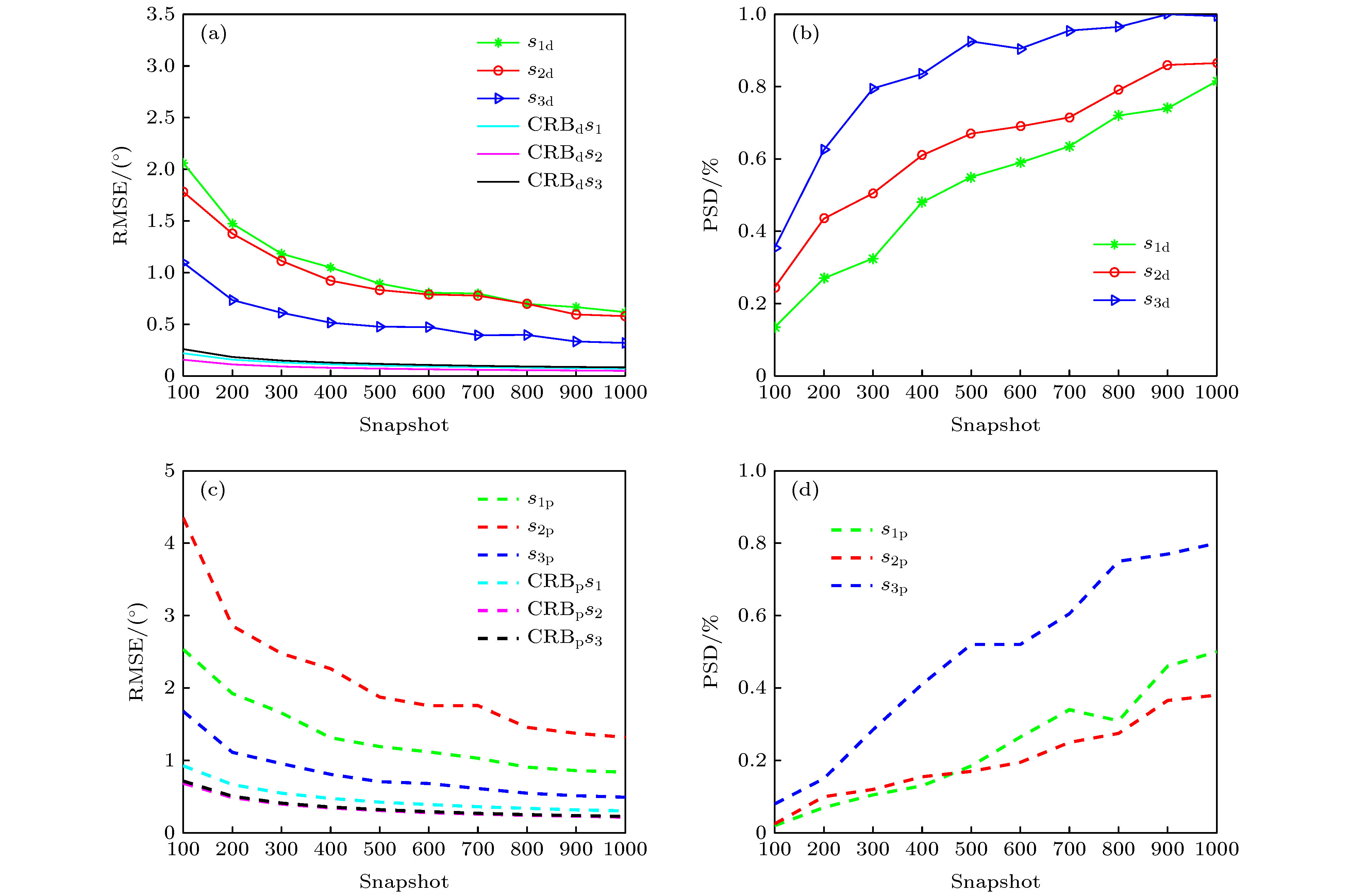 图 6 新型阵列角度和极化参数估计性能随快拍数的变化 (a) 角度估计均方误差随快拍数的变化; (b) 角度检测概率随快拍数的变化; (c) 极化估计均方误差随快拍数的变化; (d) 极化检测概率随快拍数的变化

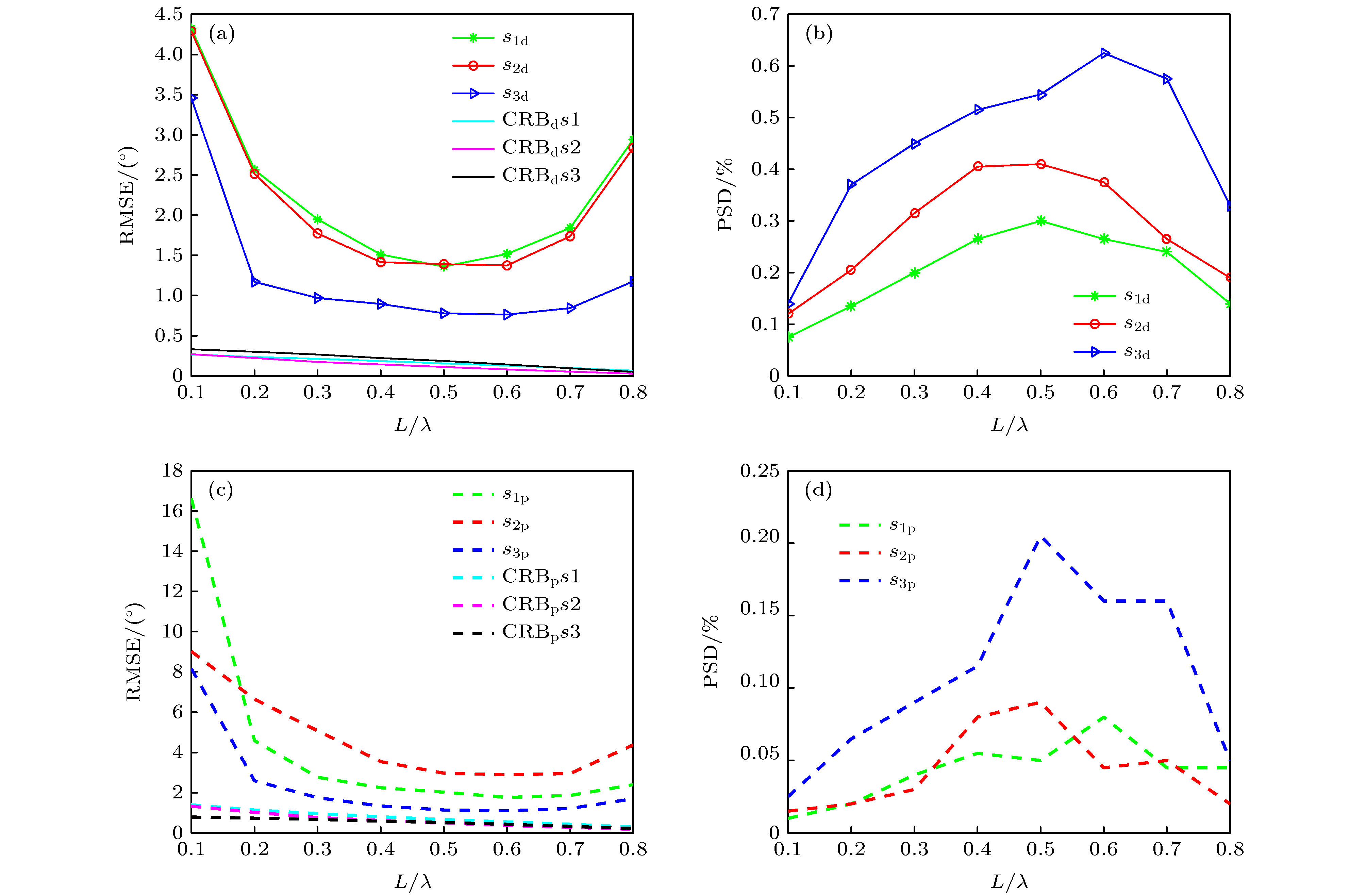 图 7 不同电偶极子的长度对角度和极化参数估计性能的影响 (a) 角度估计均方误差随电偶极子长度的变化; (b) 角度检测概率随电偶极子长度的变化; (c) 极化估计均方误差随电偶极子长度的变化; (d) 极化检测概率随电偶极子长度的变化


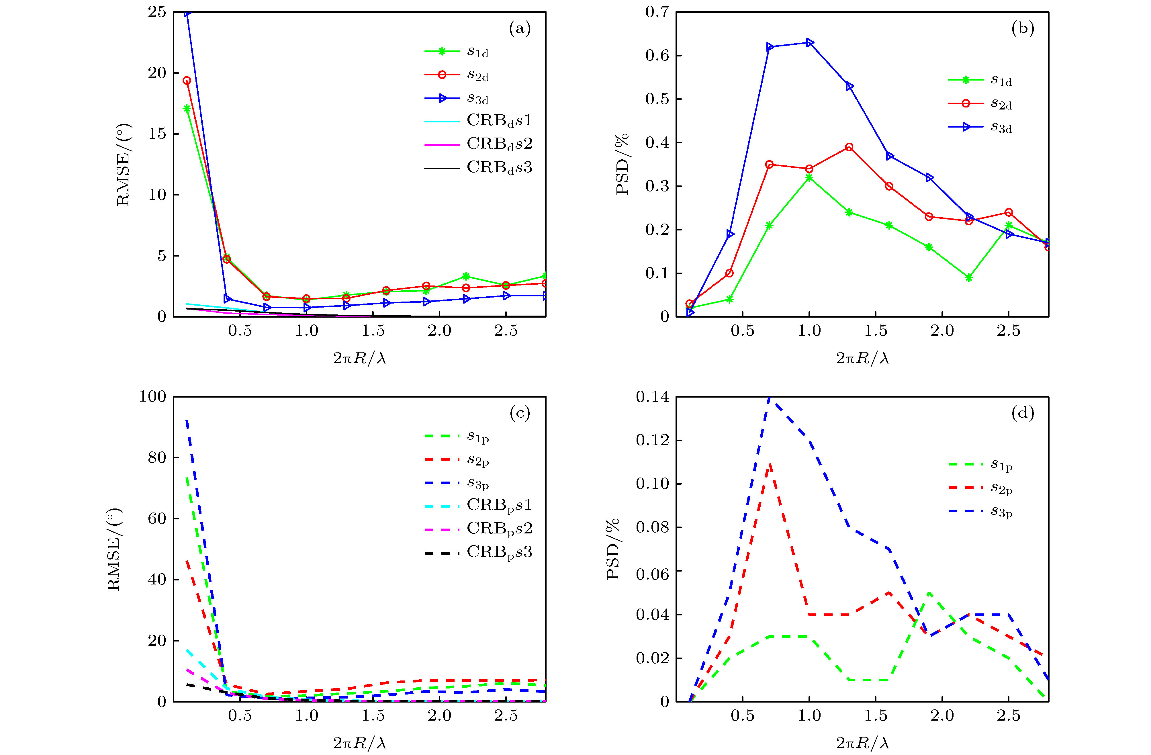 图 8 不同磁偶极子周长对角度参数和极化参数估计性能的影响 (a) 角度估计均方误差随磁偶极子周长的变化; (b) 角度检测概率随磁偶极子周长的变化; (c) 极化估计均方误差随磁偶极子周长的变化; (d) 极化检测概率随磁偶极子周长的变化


