Abstract:As an important imaging diagnostic manner in Z-pinch experiments, an X-ray streak camera can record a continuous time evolution of X-ray emission and has a better temporal resolution of about several picoseconds. Unfortunately, during experiment the transient strong electromagnetic noise produced by the device interferes with sensitive electronic components of the X-ray streak camera, making it unworkable frequently. In addition, the camera’s position is close to the load chamber so that the photocathode and metallic grid of the camera may suffer the risk of being broken by high speed charged particles and exploding debris. In order to solve this problem, a novel soft X-ray streak imaging system based on the conversion of fast scintillator and an optical streak camera is designed. In the streak camera system, the plastic scintillator foil and fiber bundles are used to convert X-ray image into optical image and transmit it into an optical streak camera which is placed in a shielding cabinet far from the target chamber. The camera system proves efficient in avoiding the damage caused by high speed particles and suppressing the electromagnetic interference. The scope of response spectrum of the camera system is given by theoretical calculation and roughly from 0.2 to 10 keV. The spatial resolution of the camera system is designed to be less than 120 microns and the temporal resolution of the camera system is calibrated to be about 1 ns in X-pinch experiments. The camera system is used in aluminum wire-array experiments to capture the time-resolved and 1D space-resolved images of imploding plasmas. The spatiotemporal distribution information about the X-ray emission is presented. On the other hand, because of the transmission of the filter in sub-kilo-electron-volt emission, the spectral response of the camera system in the sub-kilo-electron-volt photon energy range decreases obviously, which affects the physical analysis of the image. In addition, because of the slow response time of the scintillator to X-rays, the temporal resolution of the camera system decreases obviously and is about1 ns. How to solve these problems will be carried out in the future work. Keywords:Z-pinch/ X-ray/ plastic scintillator/ streak camera
${T_{{\rm{Mylar}}}}\left( E \right) = {{\rm{e}}^{ - {l_1}{\mu _{{\rm{Mylar}}}}\left( E \right)}},$
${T_{{\rm{Al}}}}\left( E \right) = {{\rm{e}}^{ - {l_2}{\mu _{{\rm{Al}}}}\left( E \right)}},$
${A_{{\rm{PS}}}}\left( E \right) = 1 - {{\rm{e}}^{ - {l_3}{\mu _{{\rm{en \text- PS}}}}\left( E \right)}}.$
式中$ {l}_{1}, {l}_{2}, {l}_{3} $分别是Mylar膜、铝膜和塑料闪烁体的厚度; ${\mu }_{\mathrm{M}\mathrm{y}\mathrm{l}\mathrm{a}\mathrm{r}}\left(E\right), {\mu }_{\mathrm{A}\mathrm{l}}\left(E\right), {\mu }_{\mathrm{e}\mathrm{n}\text-\mathrm{P}\mathrm{S}}\left(E\right)$分别表示对于不同光子能量的Mylar膜的线衰减系数、铝膜的线衰减系数和塑料闪烁体的线质能吸收系数. 图2分别给出了2 μm厚的Mylar膜和200 nm厚的铝膜对X射线的透过率、0.05 mm厚的EJ-232型塑料闪烁体对X射线的吸收效率以及诊断系统对X射线的光谱响应范围. 从图中可以看出, 光子能量小于1 keV的X射线被塑料薄膜闪烁体全部吸收, 随着光子能量的增加, 塑料闪烁体的吸收效率逐渐减少, 对于光子能量大于10 keV的X射线, 几乎全部透射. 另外, 由于挡光滤片阻挡了大部分光子能量小于1 keV的X射线, 因此相机系统对于小于1 keV范围的光谱响应, 仅分别在280和530 eV处有一个透过率约8%的透射窗口, 并且当光子能量大于700 eV后, 其透射率超过10%. 总体来说, 相机系统的光谱响应范围大约在0.2—10 keV之间, 响应峰值为1.55 keV. 图 2 Mylar膜对X射线的透过率曲线(红色虚线)、铝膜对X射线的透过率曲线(蓝色点)、塑料闪烁体对X射线的吸收效率曲线(绿色实线)以及诊断系统的光谱吸收曲线(黑色实线) Figure2. The red dash is the transmission of 2 μm thick Mylar film, the blue dot is the transmission of 200 nm thick aluminum, the green line is the absorption of the 0.05 mm thick plastic scintillator foil, and the black line is spectral response curve of the diagnostic system.
22.2.系统的时间分辨 -->
2.2.系统的时间分辨
相机系统的时间分辨主要由光学条纹相机的时间分辨、取样狭缝宽度以及塑料薄膜闪烁体对X射线的响应时间决定. 其中, 条纹相机在扫全屏时间为50—100 ns的扫速下的时间分辨小于60 ps; 取样狭缝宽度的典型尺寸为50 μm, 它在条纹相机时间长度上对应的时间分辨也小于60 ps. 由于它们远小于闪烁体对X射线的响应时间, 因此相机系统的时间分辨能力主要决定于塑料薄膜闪烁体对X射线的时间响应. 利用X箍缩[19]产生的X射线脉冲, 对厚度0.05 mm的EJ-232型塑料闪烁体的时间响应进行标定. X箍缩光源的发射光谱一般在1—10 keV范围内, 与系统的光谱响应范围较一致; X箍缩光源发射的X射线脉冲的持续时间为百皮秒量级, 远小于塑料闪烁体对X射线的响应时间(纳秒量级), 可以作为标准时间光源. 标定实验中, 同时获取X箍缩产生的X射线脉冲的辐射强度随时间变化的信息和X射线脉冲经过闪烁体转换后产生的荧光的发光强度随时间的变化信息, 通过对时间信息的对比就可以获取塑料闪烁体对X射线的时间响应参数. 实验测量中, X射线脉冲由X射线二极管测量, 闪烁体转换后产生的荧光通过光电倍增管测量, 测量结果由示波器记录, 以上测试设备和用于信号传输的同轴电缆的时间响应均小于100 ps, 满足对X射线脉冲和荧光脉冲时间参数的测量要求. 因为在X箍缩产生的X射线脉冲中, 低能光子的发射持续时间较长, 因此选择5 μm厚的Ti作为挡光滤片, 滤掉光子能量小于1.5 keV的X射线, 以保证标定光源具有较短的发光持续时间. 图3(a)给出了同一实验发次中示波器记录的X射线二极管和闪烁体-光电倍增管的输出电信号. 可以明显看出, X射线脉冲经过闪烁体转换成荧光后, 在时间坐标上存在明显的展宽现象. 信号的半高宽从290 ps增加到1230 ps; 信号上升沿(10%—90%)从200 ps增加到310 ps; 信号下降沿(10%—90%)从290 ps增加到1830 ps. 闪烁体对多个X射线脉冲信号的时间响应如图3(b)所示. 图中X射线二极管测量的结果为2个X射线脉冲信号, 其中第1个脉冲信号具有双峰结构, 同时, 从闪烁体-光电倍增管的测量结果中也可以观察到2个脉冲信号, 但是无法分辨第1个脉冲信号的双峰结构. 如果定义第一个脉冲信号的半高宽的中间时刻为这个脉冲信号的峰值时刻, 那么, 2个脉冲信号峰值时刻的时间间隔为1020 ps. 也就是说, 对于2个时间间隔为1020 ps的脉冲信号, 闪烁体具有对其进行时间分辨的能力. 图 3 塑料薄膜闪烁体对X射线时间响应特性的标定结果 Figure3. The calibration results of the time response of the scintillator foil to X-rays.
式中, t是闪烁体的厚度; θIn是当荧光从塑料闪烁体内部射出时, 折射角θRe等于传像束最大入射角时的入射角; n0 = 1和n1 = 1.58分别为真空和塑料闪烁体的折射率; 其中θRe = 25.4°. 实验中, 考虑接受到的X射线强度对图像信噪比的影响, 诊断系统的成像狭缝宽度设置为W = 50 μm, 成像物距L1 = 300 mm, 成像放大倍率M = 1, 塑料闪烁体厚度t < 0.1 mm, 可以计算得出, 系统的理论空间分辨率σ < 125 μm. 3.实验结果诊断系统在装置驱动的铝丝阵K壳层辐射光源[20]构建技术的实验中进行了考核, 拍摄到了铝等离子体发射的X射线条纹图像. 首先对诊断系统拍摄的X射线图像的本底进行确认, 获取了未加塑料闪烁体情况下的本底图像, 图像强度的平均读数与用于图像记录的CCD相机的噪音读数相当, 这说明系统中挡光滤片较好地完成了对光源中发射的可见光的屏蔽. 诊断系统拍摄的X射线条纹图像如图4(a)所示. 图像中的本底信号强度读数的平均值约450, 最强信号的读数大于10000, 图像的信噪比大于20. 图中横坐标为时间轴, “0”时刻对应X射线辐射功率的峰值时刻; 纵坐标为负载的轴向方向. 可以明显看出, 铝等离子体的发光持续时间较长, 可分为两个阶段: 以“0”时刻为中心持续时间约10 ns的主要发光阶段和超过50 ns的发光拖尾阶段. 这也与实验中拍摄到的X射线分幅图像所显示出的等离子体出现较强的不稳定性现象相符合. 图 4 诊断系统拍摄的X射线条纹图像结果 (a)铝等离子体的X射线条纹图像; (b)X射线在不同时刻沿轴向方向的辐射强度分布曲线; (c)成像系统和XRD探测器获取的X射线辐射强度随时间变化的归一化曲线比较 Figure4. Images obtained by the diagnostic system are shown: (a) The X-ray streak image of aluminum plasmas; (b) the radiation intensity distribution of x-ray source in the axial direction at different time; (c) the normalized curve of X-ray radiation measured by the diagnostic system and XRD detector.
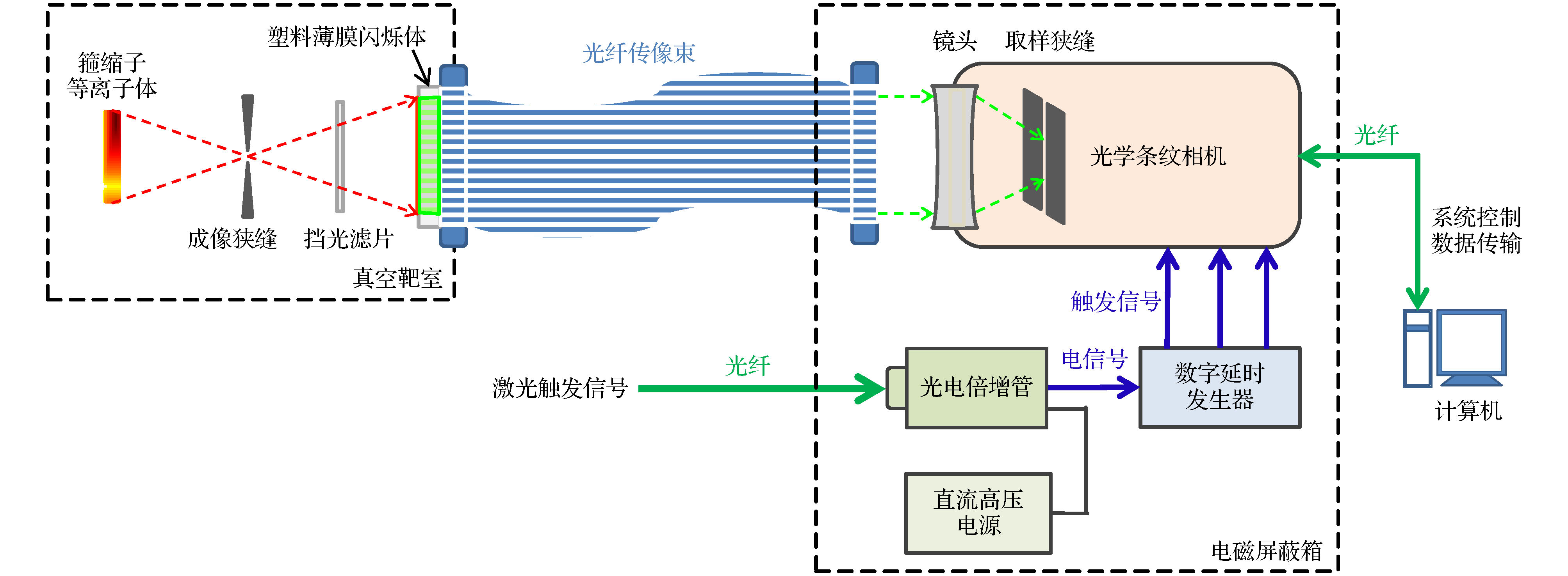 图 1 诊断系统结构和实验布局


 图 2 Mylar膜对X射线的透过率曲线(红色虚线)、铝膜对X射线的透过率曲线(蓝色点)、塑料闪烁体对X射线的吸收效率曲线(绿色实线)以及诊断系统的光谱吸收曲线(黑色实线)
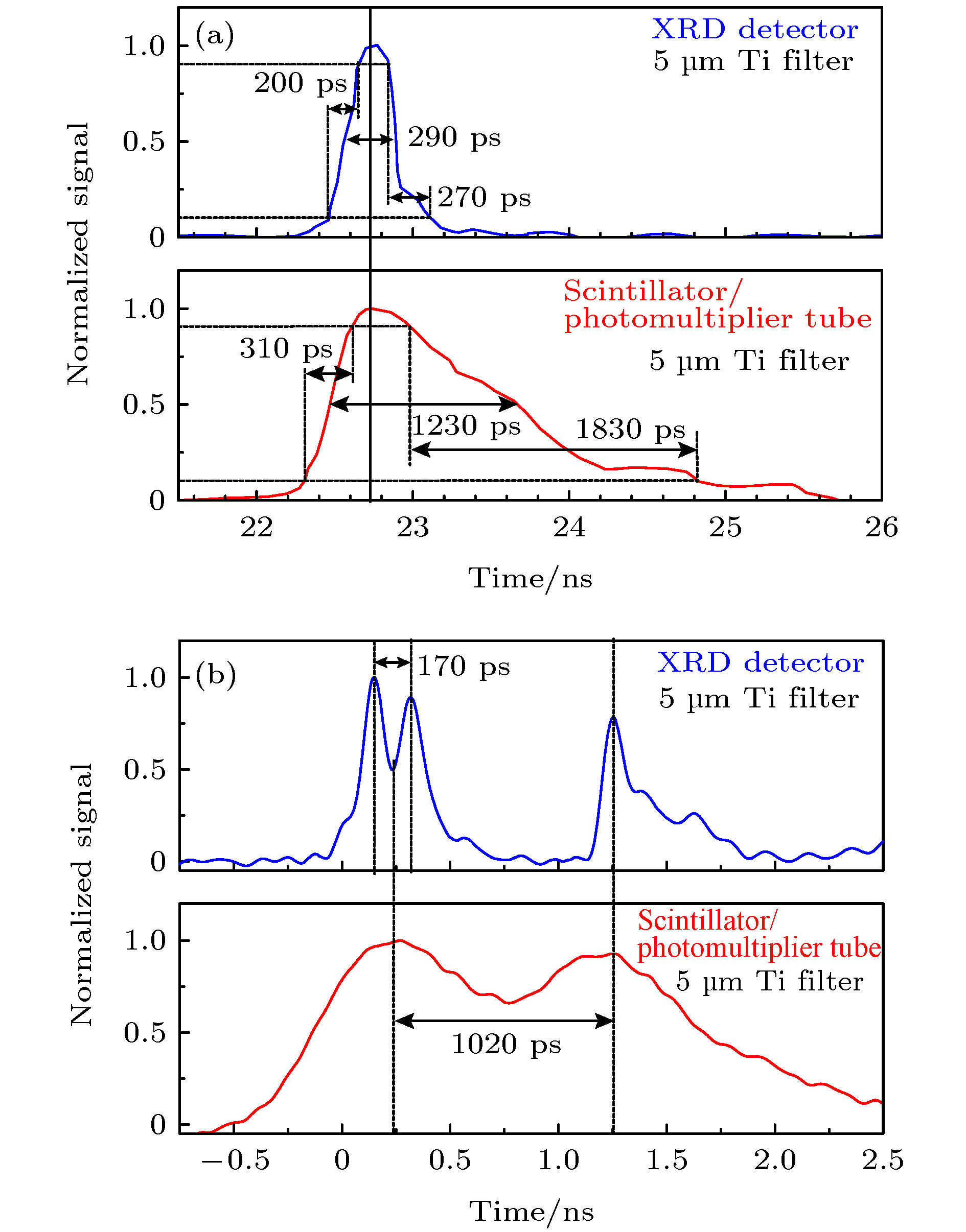 图 3 塑料薄膜闪烁体对X射线时间响应特性的标定结果
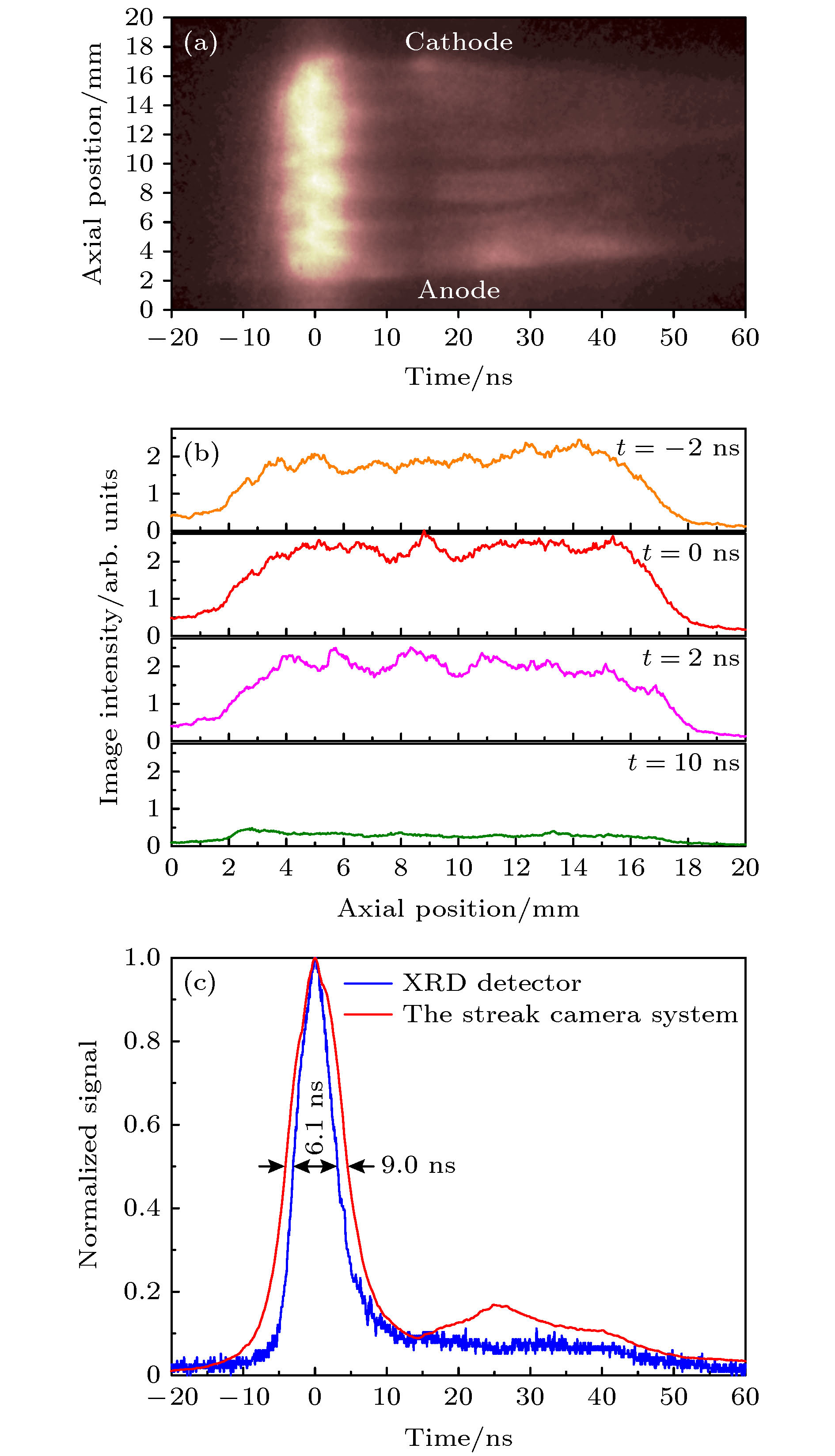 图 4 诊断系统拍摄的X射线条纹图像结果 (a)铝等离子体的X射线条纹图像; (b)X射线在不同时刻沿轴向方向的辐射强度分布曲线; (c)成像系统和XRD探测器获取的X射线辐射强度随时间变化的归一化曲线比较