1.State Key Laboratory of Underwater Acoustic Technology, Harbin Engineering University, Harbin 150001, China 2.Key Laboratory of Marine Information Acquisition and Security, Ministry of Industry and Information Technology, Harbin Engineering University, Harbin 150001, China 3.College of Underwater Acoustic Engeering, Harbin Engineering University, Harbin 150001, China
Fund Project:Project supported by the National Natural Science Foundation of China (Grant No. 11234002) and the Stability Support Program of the Bureau of National Defense Science, Technology and Industry, China (Grant No. JCKYS2020604SSJS004)
Received Date:21 August 2020
Accepted Date:18 September 2020
Available Online:13 January 2021
Published Online:20 January 2021
Abstract:In a deep sea sound channel, rays will bend due to the sound speed profile, and convergence zone will occur when the rays are intensive. Transmission loss in the convergence zone is smaller and it is conducive to acoustic detection and communication. Therefore the study of acoustic characteristics in convergence zone is always the focus of deep-sea acoustics. A long-range sound propagation experiment is conducted in the South China Sea. An equivalent broadband explosive sound source of 1 kg is placed at a depth of 200 m, and the hydrophone receives the data at 3146 m far. The processing and analysis of the experimental data indicate that there is a convergence zone below the sound channel axis in the incomplete deep channel. Compared with the upper turning point convergence zone near the surface, this convergence zone has a high convergence gain at a long distance. The caustic lines of refracted type and refracted surface-refleted type are determined by means of ray-normal mode theory. It is found that the location of the deep convergence zone observed in the experiment is consistent with the position of the refracted caustic line. It is proved that the convergence zone is a lower turning point convergence zone formed by the superposition of a large number of normal modes in the same phase, and it has a convergence effect at a certain depth below the sound channel axis in the deep sea. The formation conditions of the convergence zone and the influence of sound source depth on the caustic structure of the convergence zone are studied. The comparisons of the transmission loss and the width between the upper and lower turning point convergence zone at a long distance aremade. The analysis shows that the convergence gain in the seventh lower turning point convergence zone is still no less than 10 dB. The influence of the vertical structure of sound velocity on the lower turning point convergence zone is studied. The theoretical analysis results are in good agreement with the experimental data. Keywords:convergence effect/ caustics/ lower turning point/ transmission loss
频率范围为178—224 Hz, 如图2所示的声速剖面, 以1 Hz为计算步长, 在每一个频点利用kraken软件进行声场计算, 然后利用(4)式计算声场平均能量, 然后依据此平均能量计算得出频率平均后的传播损失, 得到图3所示的传播损失伪彩图. 图 3 频率平均传播损失伪彩图 Figure3. Pseudo color map of transmission loss with frequency averaged.
如图6所示, 画出了接收深度位于3146 m时RR型声线所对应的简正波归一化幅值之间的关系. 从图6中可以看出, 第12阶RR型声线所对应的简正波的模态强度幅值函数取得最大值, 意味着该阶简正波对这一接收深度处的声场起主要贡献, $\Delta n$的选取为中心阶数$n$左右两侧极小值对应的阶数, 如图6中$\Delta n = 12$. 图 6 3146 m接收深度时RR型声线所对应的简正波归一化幅值 Figure6. Normalized modal amplitudes, with receiver at 3146 m.
在下反转点会聚区接收深度3146 m处, 将RR型声线所对应的简正波从第1阶开始每相邻$\Delta n$阶相位差取均值, 得到图7所示图像, 从图7中可以看出, 以阶数$n$为中心, 相邻$\Delta n$阶简正波的平均相位差约为0, 这表明在该会聚区处, 以阶数$n$为中心, 相邻的$\Delta n$阶简正波几乎是同向叠加的, 因此能够产生更大声强. 图 7 每$\Delta n$阶简正波相位差均值 Figure7. The mean value of the phase difference of $\Delta n$ normal modes.
4.下反转点会聚区的特性24.1.下反转点会聚区的形成条件 -->
4.1.下反转点会聚区的形成条件
由于下反转点会聚区是在下反转点附近出现的会聚区, 因此, 下反转点会聚区的形成与是否存在下反转点有着密切的联系. 图8根据实验测得的声速剖面, 画出了不同声速剖面时传播损失伪彩图, 其中完整声道的声速剖面为实验测得的声速剖面进行延伸得到的, 延伸的部分在图中用虚线表示, 并在传播损失伪彩图中标注出了下反转点会聚区的位置. 从图8中可以看出, 在完整声道中, 由于声道轴以下的深度足够深, 总会有声线在声道轴以下反转, 因此完整声道中一直存在下反转点会聚区, 且会聚区位置位于声源共轭深度至海面共轭深度之间. 在不完整声道中, 如果声源共轭深度小于海底深度, 则会有声线在声道轴以下反转, 形成下反转点会聚区, 且会聚区位置位于声源共轭深度至海底之间; 如果声源共轭深度大于海底深度, 则没有声线能够在声道轴以下反转, 从而也无法形成下反转点会聚区. 图 8 不同声速剖面传播损失对比图 (a) 完整声道; (b) 不完整声道声源深度声速小于海底声速; (c) 不完整声道声源深度声速大于海底声速 Figure8. Comparisons of transmission losses at different sound speed profile: (a) Complete channel; (b) incomplete channel with source depth sound speed less than bottom sound speed; (c) incomplete channel with source depth sound speed greater than bottom sound speed.
24.2.声源深度对下反转点会聚区焦散结构的影响 -->
4.2.声源深度对下反转点会聚区焦散结构的影响
本次远海声传播实验海域为不完整声道, 因此着重研究不完整声道中声道轴以下的下反转点会聚区. 从图5中可以看出, RR型声线所形成的焦散线在每一个下反转点会聚区内有两部分强度较大, 分别由负角度出射的声线与正角度出射的声线所形成, 且负角度出射的声线所形成的焦散线滞后于正角度出射的声线所形成的焦散线. 声源深度对下反转点会聚区的焦散结构具有一定的影响. 从图8的分析中可知, 若声源深度处声速大于海底声速, 则不会形成下反转点会聚区, 当声源深度声速小于海底声速时, 图9分别画出了声源深度为100, 200, 和500 m时负角度出射声线以及正角度出射声线的RR型声线所形成的焦散线位置结构示意图. 从图9中可以看出, 当声源深度较浅的时候, 负角度出射声线以及正角度出射声线的RR型声线所形成的焦散线趋于重合, 随着声源深度的增大, 负角度出射声线所形成的焦散线滞后于正角度出射声线所形成的焦散线, 并且声源深度越深, 两类焦散线之间的距离越大. 随着水平距离的增加, 两类焦散线之间的距离也在逐渐增加, 且焦散线的倾斜程度也在逐渐增加. 从图9中也可以看出, 在不完整声道的声道轴以下区域, 下反转点会聚区从声源的共轭深度开始, 一直到海底附近的一定深度范围内都有很强的会聚效应. 图 9 不同声源深度时RR型声线所形成的焦散线结构示意图, 实线为正角度出射声线所形成的焦散线, 虚线为负角度出射声线所形成的焦散线 (a) 声源深度100 m; (b) 声源深度200 m; (c) 声源深度500 m Figure9. Schematic diagram of the structure of caustic lines formed by RR type rays at different source depths. The full line is the caustic line formed by the positive angle of departure, and the imaginary line is the caustic line formed by the negative angle of departure: (a) 100 m; (b) 200 m; (c) 500 m.
选取了接收4000 m, 分别画出了声源深度100, 200以及500 m时传播损失图像, 如图10(a)所示, 并将第7个下反转点会聚区处的传播损失放大显示于图10(b)中. 从图10中可以看出, 随着声源深度的增加, 下反转点会聚区的宽度逐渐增加, 同时传播损失也逐渐增大. 图 10 接收深度4000 m传播损失图像 (a) 0?450 km; (b) 第7个下反转点会聚区 Figure10. Transmission loss with receiver depth at 4000 m: (a) 0?450 km; (b) enlarge view of the 7th lower turning point convergence zone.
24.3.下反转点会聚区空间分布特点 -->
4.3.下反转点会聚区空间分布特点
为了对比下反转点会聚区与上反转点会聚区, 选取了声源200 m, 接收深度127 m以及127 m的共轭深度3500 m, 根据(4)式计算出平均能量, 得出两个接收深度的传播损失曲线如图11(a)所示. 从图11(a)中可以看出, 随着水平距离的增大, 下反转点会聚区的传播损失逐渐小于上反转点会聚区, 在第7个会聚区, 下反转点会聚区传播损失低于上反转点会聚区传播损失约5 dB. 图11(b)为第7个会聚区的局部放大图, 从图中可以看出, 随着距离增大, 上反转点会聚区的宽度逐渐展宽, 在第7个上反转点会聚区处的会聚区宽度已达10 km以上, 而下反转点会聚区在第7个下反转点会聚区处的会聚区宽度仍为5 km左右. 图 11 127与3500 m接收深度传播损失对比 (a) 0?450 km; (b) 第7个会聚区处 Figure11. Comparison of transmission losses with receiver depth at 127 m and 3500 m: (a) 0?450 km; (b) the 7th convergence zone.
24.4.声速垂直结构变化对下反转点会聚区的影响 -->
4.4.声速垂直结构变化对下反转点会聚区的影响
深海声道表面层声速受季节变化大, 在夏季为负梯度声速, 在冬季为正梯度声速, 为了研究声速垂直结构的变化对下反转点会聚区的影响, 图12分别画出了声源位于200 m时夏季和冬季声速剖面情况下下反转点会聚区焦散线位置与传播损失伪彩图的对比. 从图12可以看出, 在不完整声道中, 下反转点会聚区的位置并不受冬夏声速变化的影响, 因为在不完整声道中, 下反转点会聚区的范围是从声源共轭深度到海底, 表面层的声速变化并未对声源深度的声速产生影响, 因此也未改变声源共轭深度. 此外, 冬季由于表面层正梯度声速产生的声道轴的声速仍然大于海底声速, 因此下反转点会聚区的范围仍到海底为止, 因此, 冬季时下反转点会聚区的范围与夏季时一致. 图 12 冬夏声速剖面下反转点会聚区焦散线对比图 (a) 夏季; (b) 冬季 Figure12. Comparisons of caustics at lower turning point convergence zone in summer and winter: (a) Summer; (b) winter.

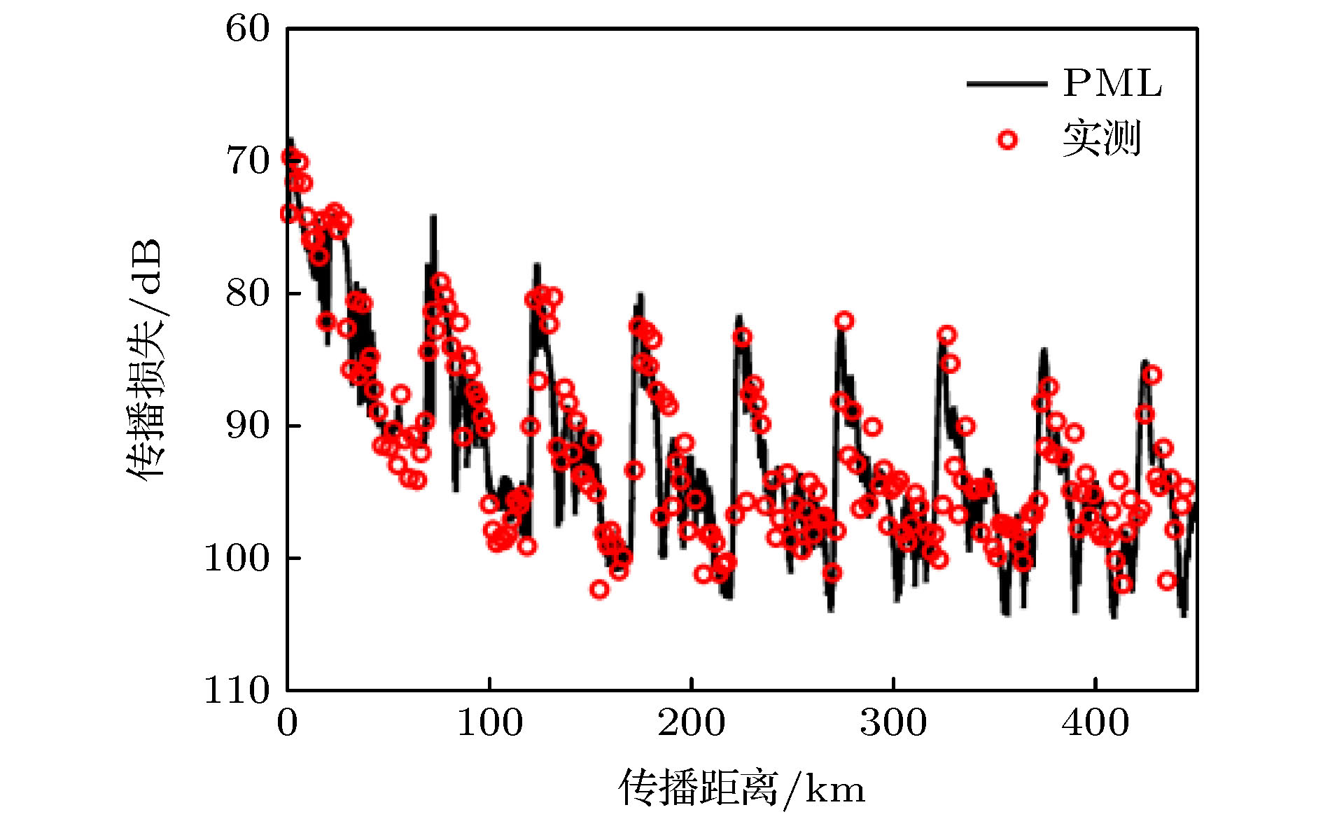 图 1 200 Hz时声压传播损失曲线与实验数据对比图[26]


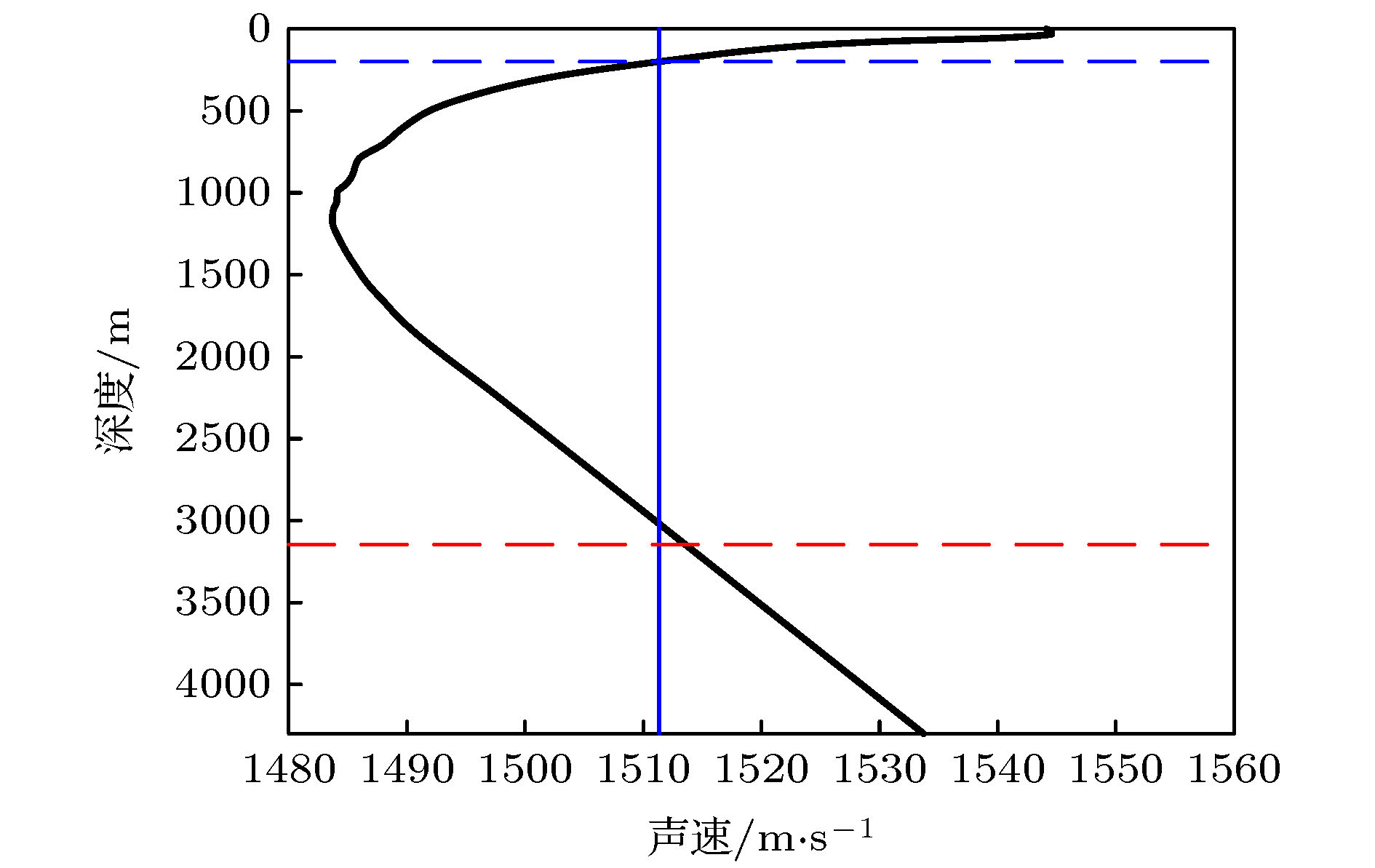 图 2 实验海区声速剖面分布
 图 3 频率平均传播损失伪彩图


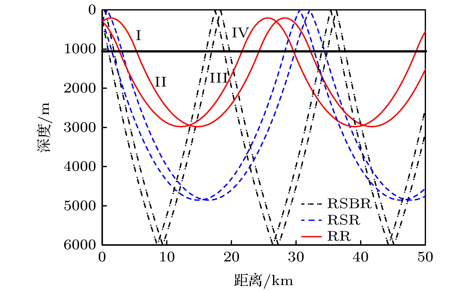 图 4 三类声线示意图


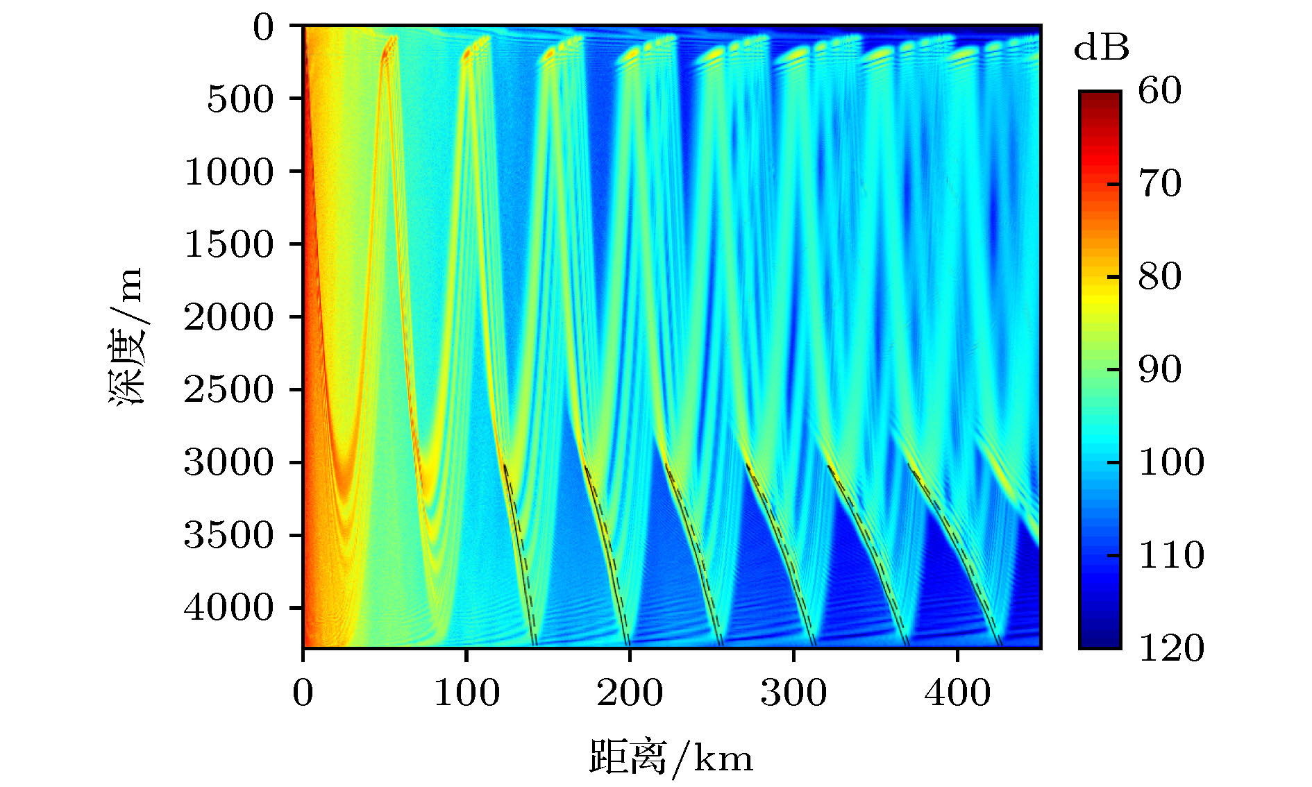 图 5 RR型声线所形成的焦散线与传播损失伪彩图对比


 图 6 3146 m接收深度时RR型声线所对应的简正波归一化幅值


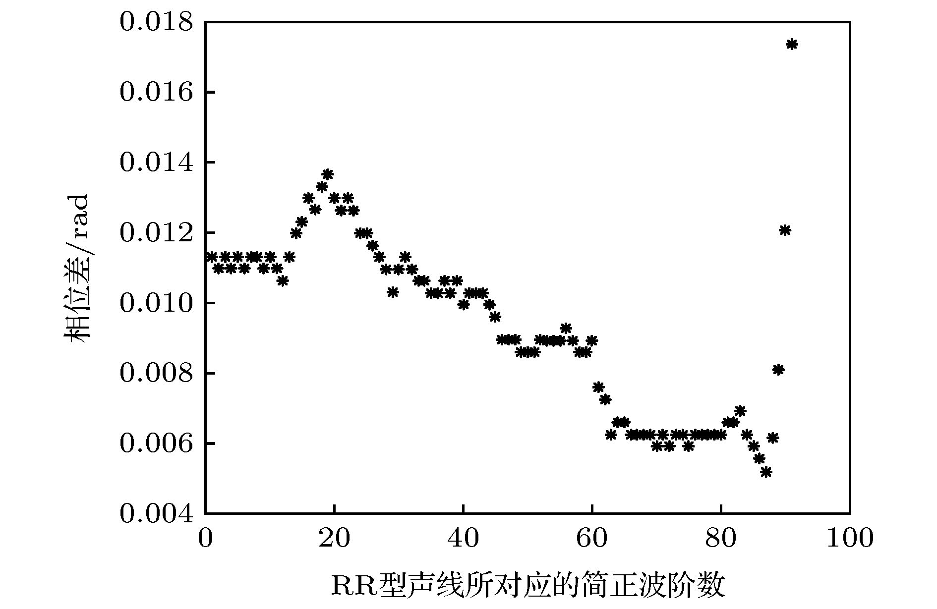 图 7 每
图 7 每

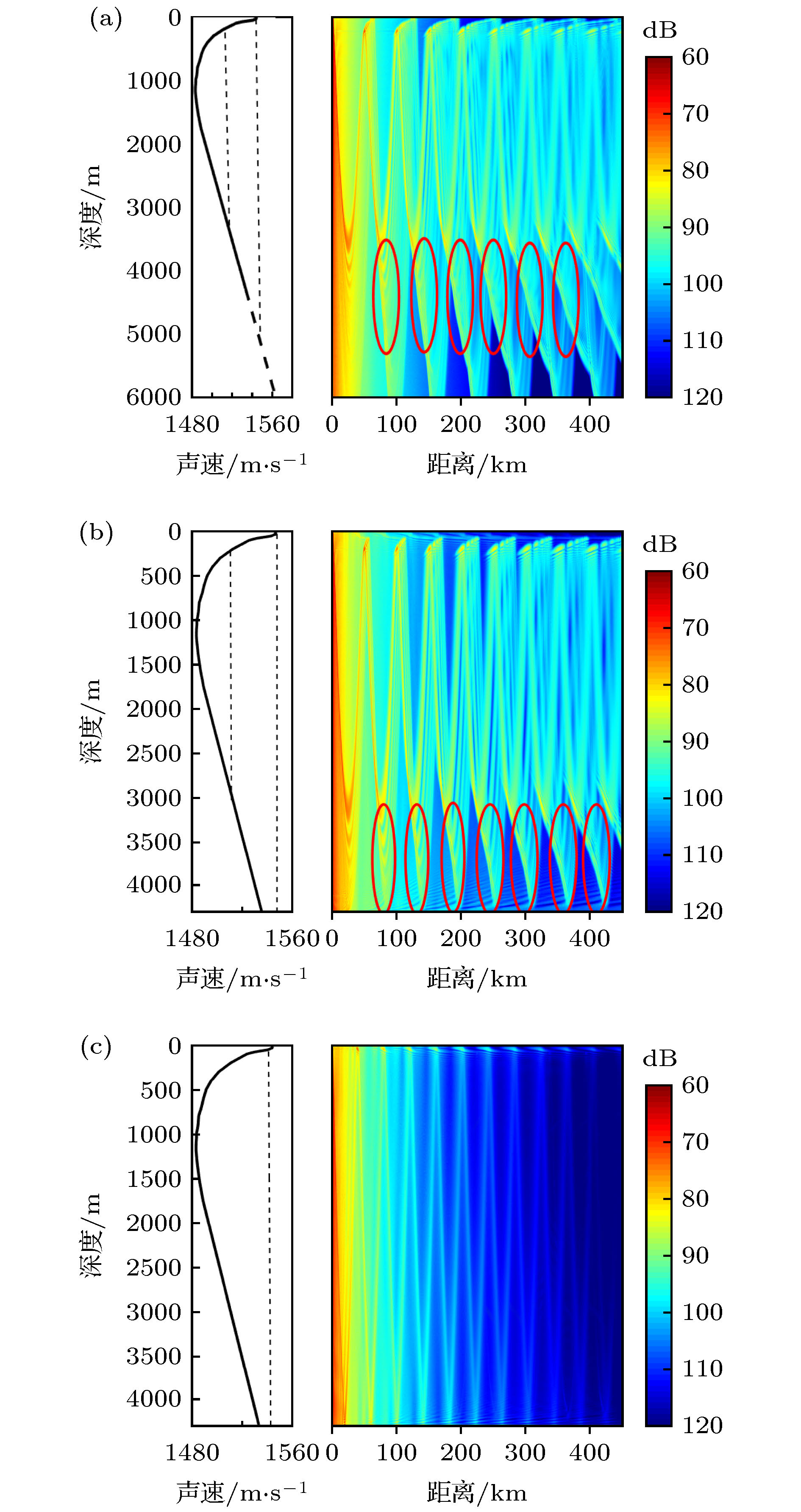 图 8 不同声速剖面传播损失对比图 (a) 完整声道; (b) 不完整声道声源深度声速小于海底声速; (c) 不完整声道声源深度声速大于海底声速
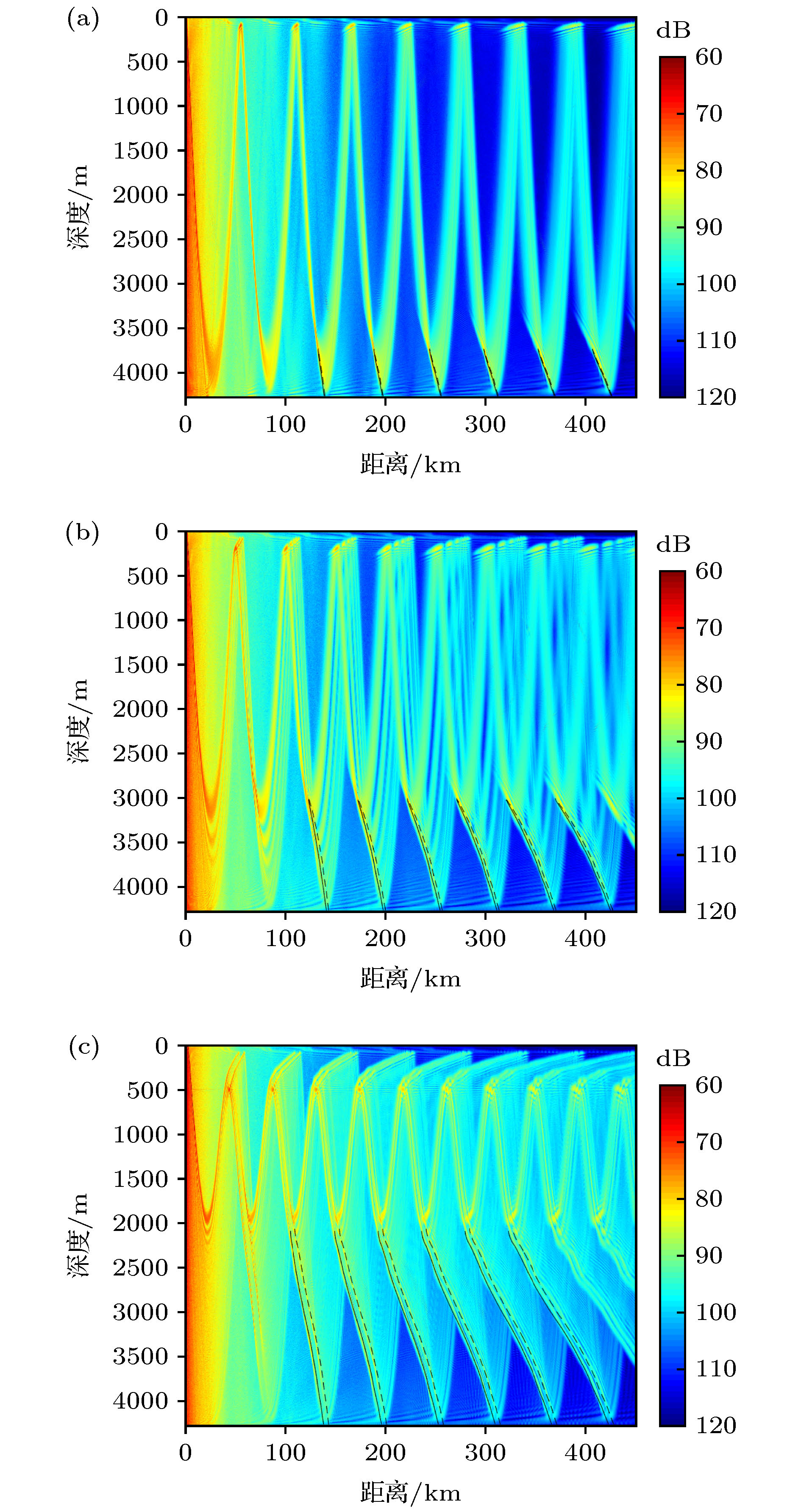 图 9 不同声源深度时RR型声线所形成的焦散线结构示意图, 实线为正角度出射声线所形成的焦散线, 虚线为负角度出射声线所形成的焦散线 (a) 声源深度100 m; (b) 声源深度200 m; (c) 声源深度500 m
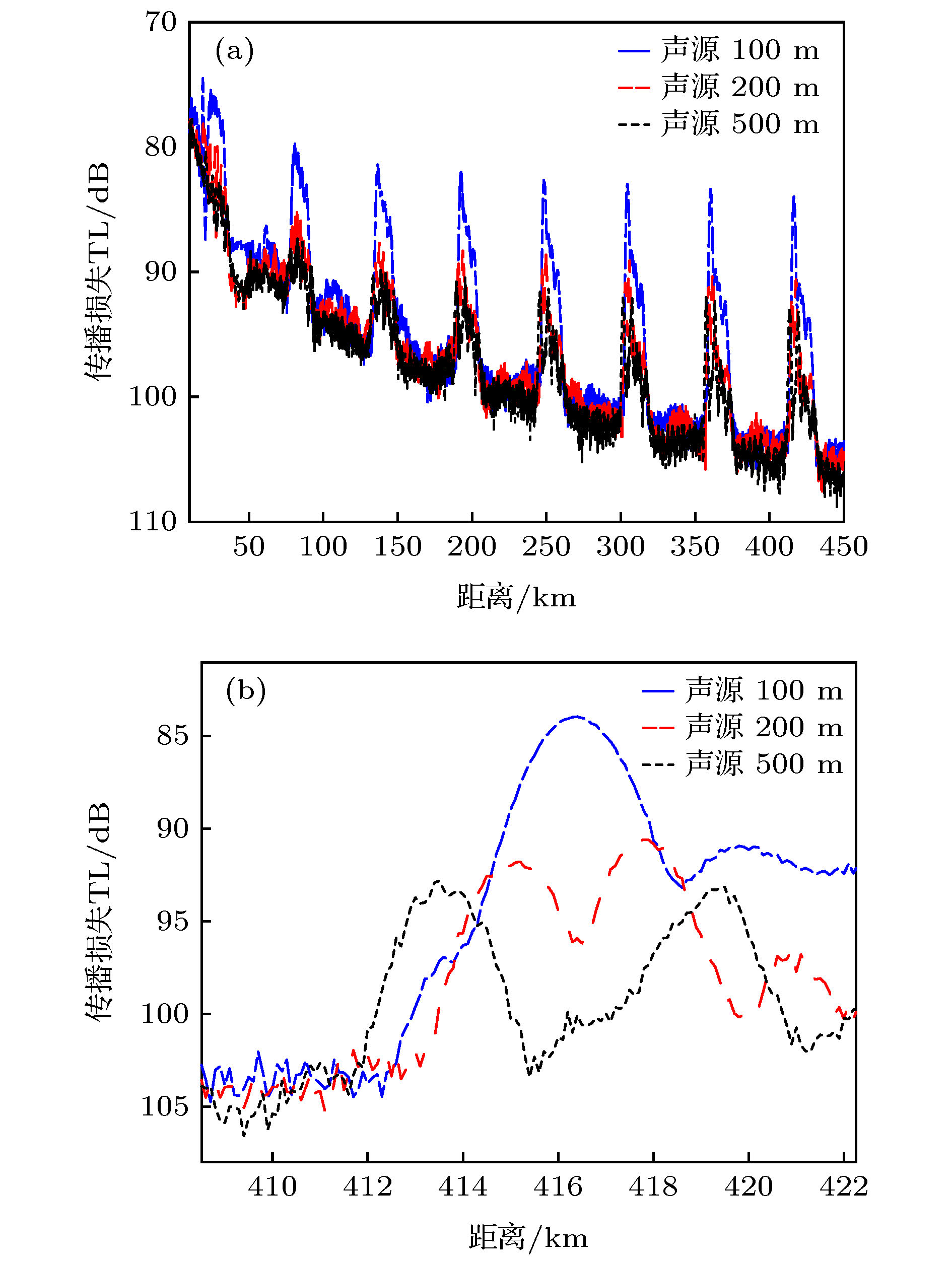 图 10 接收深度4000 m传播损失图像 (a) 0?450 km; (b) 第7个下反转点会聚区
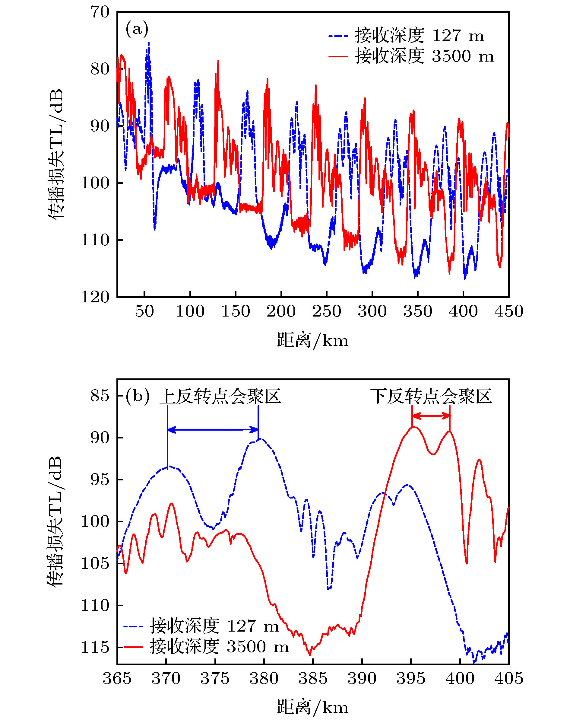 图 11 127与3500 m接收深度传播损失对比 (a) 0?450 km; (b) 第7个会聚区处
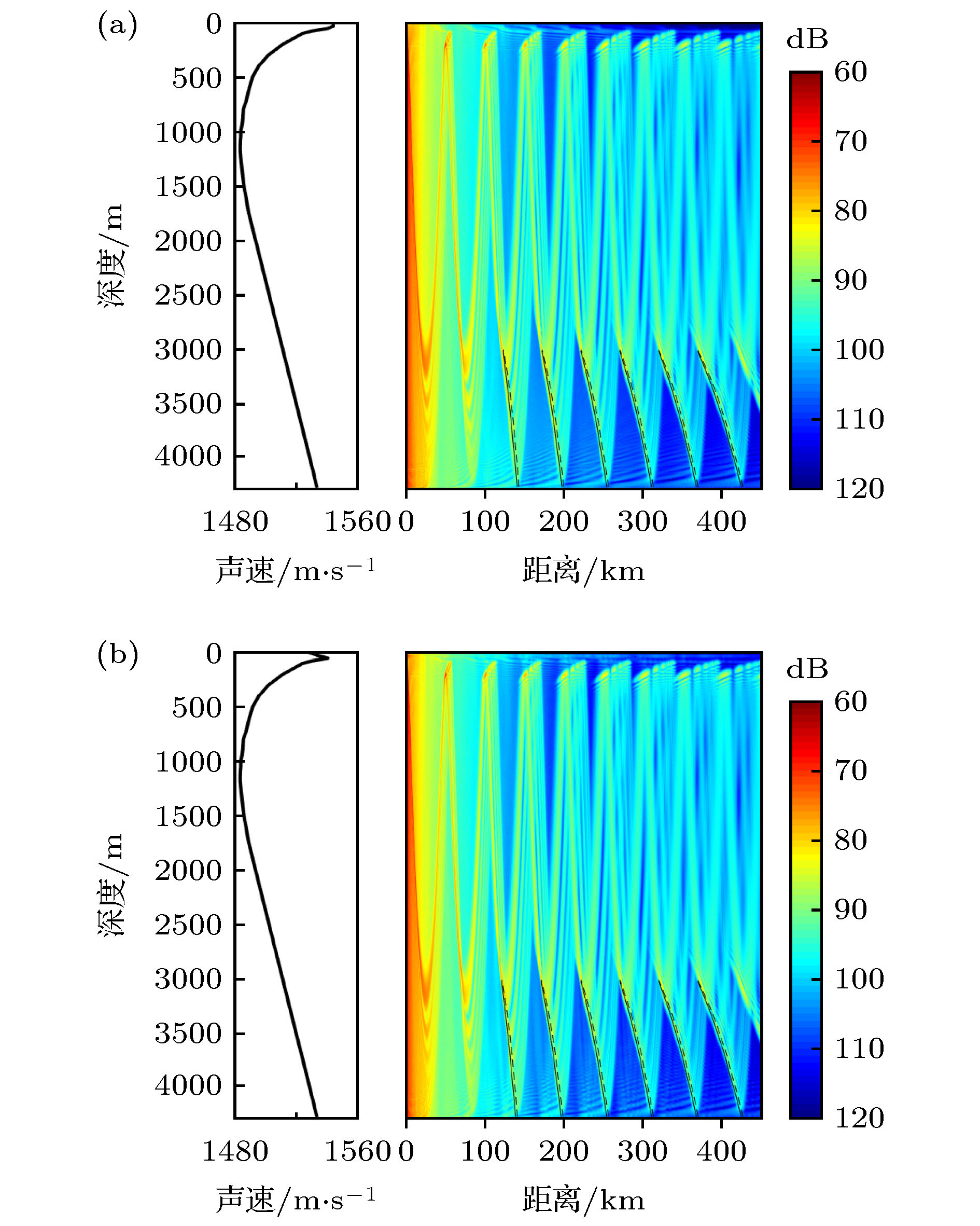 图 12 冬夏声速剖面下反转点会聚区焦散线对比图 (a) 夏季; (b) 冬季