1.College of Physics and Optoelectronics, Taiyuan University of Technology, Taiyuan 030024, China 2.Key Laboratory of Advanced Transducers and Intelligent Control System, Ministry of Education, Taiyuan University of Technology, Taiyuan 030024, China 3.Centre for Translational Atomaterials, Swinburne University of Technology, Melbourne 3122, Australia
Fund Project:Project supported by the National Natural Science Foundation of China (Grant Nos. 11904255, 51702226)
Received Date:11 April 2020
Accepted Date:28 April 2020
Available Online:07 June 2020
Published Online:20 September 2020
Abstract:Recently, quantum computing and information processing based on photons has become one research frontier, attracting significant attentions. The optical asymmetric transmission devices (OATD), having similar function to the diode in electric circuitry, will find important applications. In particular, the OATDs based on nanophotonic structures are preferred due to their potential applications in the on-chip integration with other photonic devices. Therefore, there have been numerous applications of OATDs based on different nanostructures, including composite grating structures, metasurfaces, surface plasmon polaritons, metamaterials, photonic crystals (PhCs). However, in general, those designs show relatively low forward transmittance (< 0.5) and narrow working bandwidth (< 100 nm), and they are able to work with only one polarization state. This makes the current OATDs unsuitable for many applications. To solve this challenge, here we design a two-dimensional (2D) PhC heterostructure based on the self-collimating effect and bandgap properties. The PhC heterostructure is composed of two square lattice 2D PhCs (PhC 1 and PhC 2) on a silicon substrate with different lattice shapes and lattice constants. The PhC 1 is composed of periodically arranged silicon cylinders in air. Meanwhile, the PhC 2 is an square air hole array embedding in silicon. The two PhCs are integrated with an inclined interface with an angle of 45° with respect to the direction of incident light. The plane wave expansion method is used to calculate the band diagrams and equal frequency contours (EFCs) of the two PhCs. As the propagation directions of light waves in PhCs are determined by the gradient direction of the EFCs, we are able to control the light propagation by controlling the EFCs of PhCs. By engineering the EFCs, the PhC 2 shows strong self-collimation effect in a broad wavelength range with a central wavelength of 1550 nm for both TE and TM polarization. By self-collimating the forward incident light from different incident angles to couple to the output waveguide, we are able to significantly increase the forward transmittance to > 0.5 for both TE and TM polarized light. Meanwhile, the backward transmittance can be effectively cut off by the unique dispersion properties of the PhC heterostructures. In this way, the heterostructure is able to achieve polarization independent asymmetric transmission of light waves in a broad wavelength range. To visualize the light propagation in the PhC heterostructure, we use the finite-difference-time-domain method to calculate the electric intensity distributions of the forward and backward propagation light of both TE and TM polarization at a wavelength of 1550 nm. Strong self-collimation effect of forward propagation light and the nearly complete blockage of backward propagation light can be identified unambiguously in the intensity plots, confirming the theoretical analysis. The calculation of transmittance and contrast ratio spectra show that the asymmetric transmission wavelength bandwidth can reach 532 nm with the forward transmittance and contrast ratio being 0.693 and 0.946 at an optical communication wavelength of 1550 nm for TE polarized light. On the other hand, for the TM polarized light, the asymmetric transmission wavelength bandwidth is 128 nm, the forward transmittance and contrast ratio are 0.513 and 0.972, respectively, at 1550 nm wavelength. Thus, it is confirmed that the PhC heterostructure achieves highly efficient, broadband and polarization independent asymmetric transmission. Finally, to further improve the forward transmittance of the TE polarized light, we modulate the radius of the front row of photonic lattice of PhC 1 at the interface. It shows that the forward transmittance can be further improved to a record high value of 0.832 with a bandwidth of 562 nm for TE polarized light. Our design opens up new possibilities for designing OATDs based on PhCs, and will find broad applications, for the design can be realized by current nanofabrication techniques. Keywords:self-collimation/ photonic bandgap/ heterostructure/ asymmetric transmission
为了更好地分析TE和TM偏振光在光子晶体中的传输性能, 采用平面波展开法分别计算PhC 1和PhC 2的能带图, 如图2(a)和图2(b)所示, 以及等频图(equal frequency contour, EFC), 如图2(c)—图2(f)所示. 图 2 (a) PhC 1能带图; (b) PhC 2能带图, 插图为PhC 2在Γ—X方向的能带; (c) PhC 1在TE偏振模式第一条能带EFC; (d) PhC 2在TE偏振光下第四条能带EFC (蓝线表示TE偏振光1550 nm处的频带); (e) PhC 1在TM偏振光第一条能带EFC; (f) PhC 2在TM偏振光第三条能带EFC (红线表示TM模式1550 nm处的频带) Figure2. (a) Photonic band diagrams of PhC 1; (b) the photonic band diagrams of PhC 2, where the insert shows the energy band of PhC 2 in Γ-X direction; (c) the first band EFC of PhC 1 under TE polarized light; (d) the fourth band EFC of PhC 2 under TE polarized light (blue lines represent TE mode at the wavelength of 1550 nm); (e) the first band EFC of PhC 1 under TM polarized light; (f) the third band EFC of PhC 2 under TM polarized light (red lines represent TM mode at 1550 nm).
为了分析该结构在宽波段的透射特性, 利用时域有限差分法计算异质结构透射率光谱图, 结果如图4所示. 正向透射率和反向透射率分别用$ {T}_{\rm{f}} $和$ {T}_{\rm{b}} $表示, 透射对比度定义为$ C=({T}_{\rm{f}}-{T}_{\rm{b}})/({T}_{\rm{f}}+{T}_{\rm{b}}) $, 其工作带宽定义为正向透射率高于0.5的区域, 如图4中灰色区域所示. 对于TE偏振光, 如图4(a)所示, 在1408—1940 nm (带宽532 nm)范围内, 正向透射率$ {T}_{\rm{f}} $ > 0.5; 在1510 nm波长处具有最大正向透射率0.746, 透射对比度为0.932. 在波长1550 nm的通信波段, 正向透射率和透射对比度分别为0.693和0.946. 对于TM偏振光, 如图4(b)所示, 传输波长带宽仅为128 nm, 带宽较窄, 最高正向透射率为0.567. 在1550 nm的通信频段, 正向透射率和透射对比度分别为0.513和0.972. 因此, 该结构能够在宽频带范围内实现TE和TM偏振态的高效率非对称传输. 图 4 异质结构透射谱 (a) TE偏振光; (b) TM偏振光; 其中灰色区域表示结构工作带宽 Figure4. Transmittance spectra of heterostructure: (a) TE polarized light, (b) TM polarized light. The grey region represents the asymmetric transmission working wavelength range, where forward transmission is higher than 0.5.
3.优化结构分析为了提高非对称传输特性, 对光子晶体异质结构进行进一步优化. 考虑到影响正向透射率和透射对比度的各种因素, 研究发现通过改变异质界面处PhC 1硅圆柱半径的大小R (如图5红色区域所示)可以进一步增加光子晶体PhC 1和PhC 2之间的耦合效率, 提高TE偏振光正向透射率和透射对比度. 图 5 光子晶体异质结优化示意图, 其中被优化的光子晶体结构通过红色长方形标注 Figure5. Schematic of optimization of photonic crystal heterostructure, where the row of photonic lattice is highlighted by the red square is optimized.
如图6所示, 当R = 55 nm时, 非对称传输波长带宽可达448 nm, 在通信波段1550 nm处正向透射率为0.579, 透射对比度为0.941. 随着半径的增大, 正向透射率也增大, 当R = 70 nm, 在通信波段1550 nm处正向透射率高达0.832, 透射对比度达到了0.944. 此时的非对称传输波长带宽为562 nm. 当半径R = 75 nm时, 虽然非对称传输波长带宽有一定的增加, 达到568 nm, 但与半径R = 70 nm时相比, 正向透射率减少到0.803. 图 6 异质结构界面处PhC 1不同半径硅圆柱TE偏振光透射谱 (a) R = 55 nm; (b) R = 65 nm; (c) R = 70 nm; (d) R = 75 nm Figure6. Transmittance spectra of the TE polarized light with different radii of PhC 1 photonic lattice at heterostructure interface: (a) R = 55 nm; (b) R = 65 nm; (c) R = 70 nm; (d) R = 75 nm.

 图 1 硅基光子晶体异质结构示意图
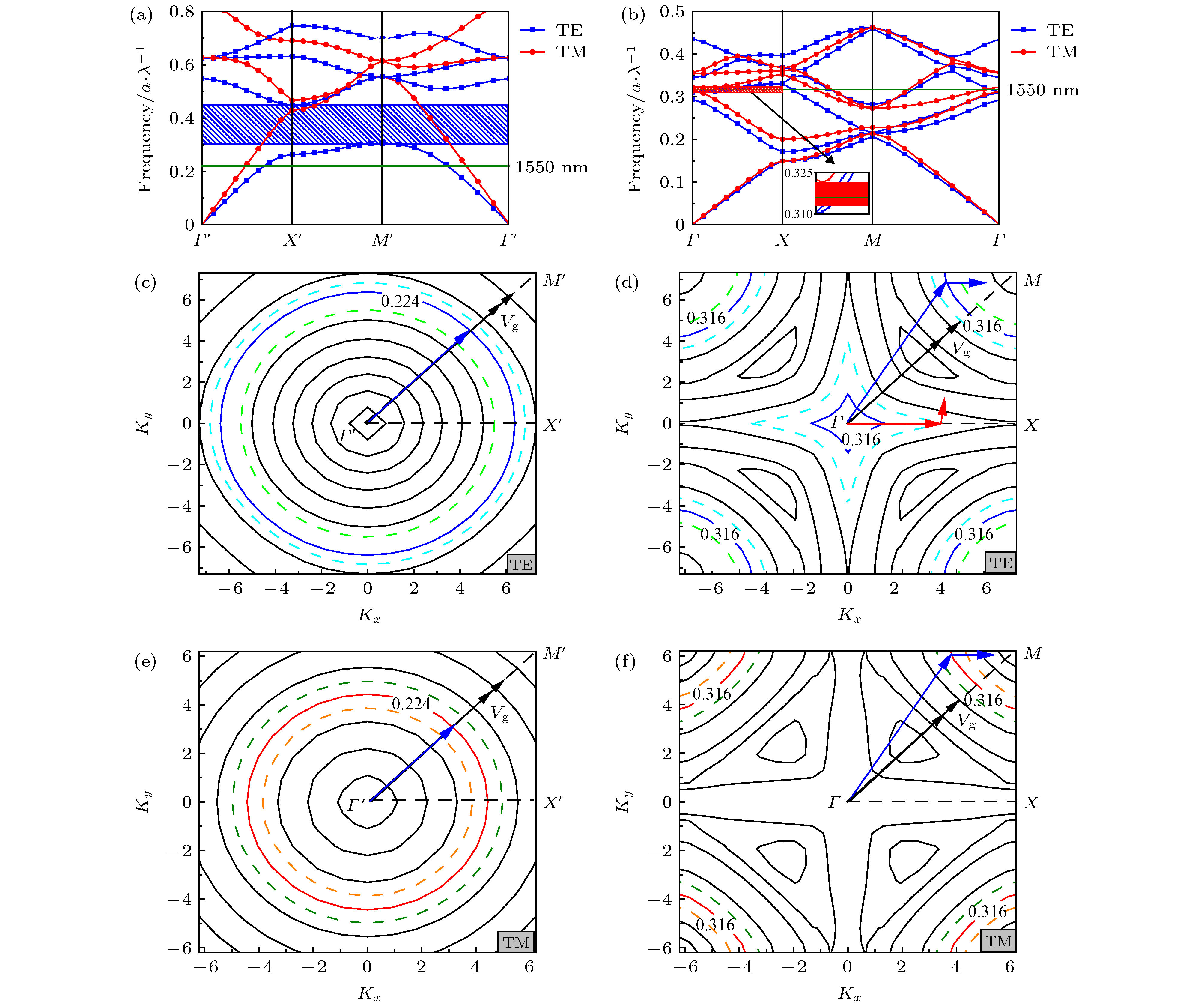 图 2 (a) PhC 1能带图; (b) PhC 2能带图, 插图为PhC 2在Γ—X方向的能带; (c) PhC 1在TE偏振模式第一条能带EFC; (d) PhC 2在TE偏振光下第四条能带EFC (蓝线表示TE偏振光1550 nm处的频带); (e) PhC 1在TM偏振光第一条能带EFC; (f) PhC 2在TM偏振光第三条能带EFC (红线表示TM模式1550 nm处的频带)
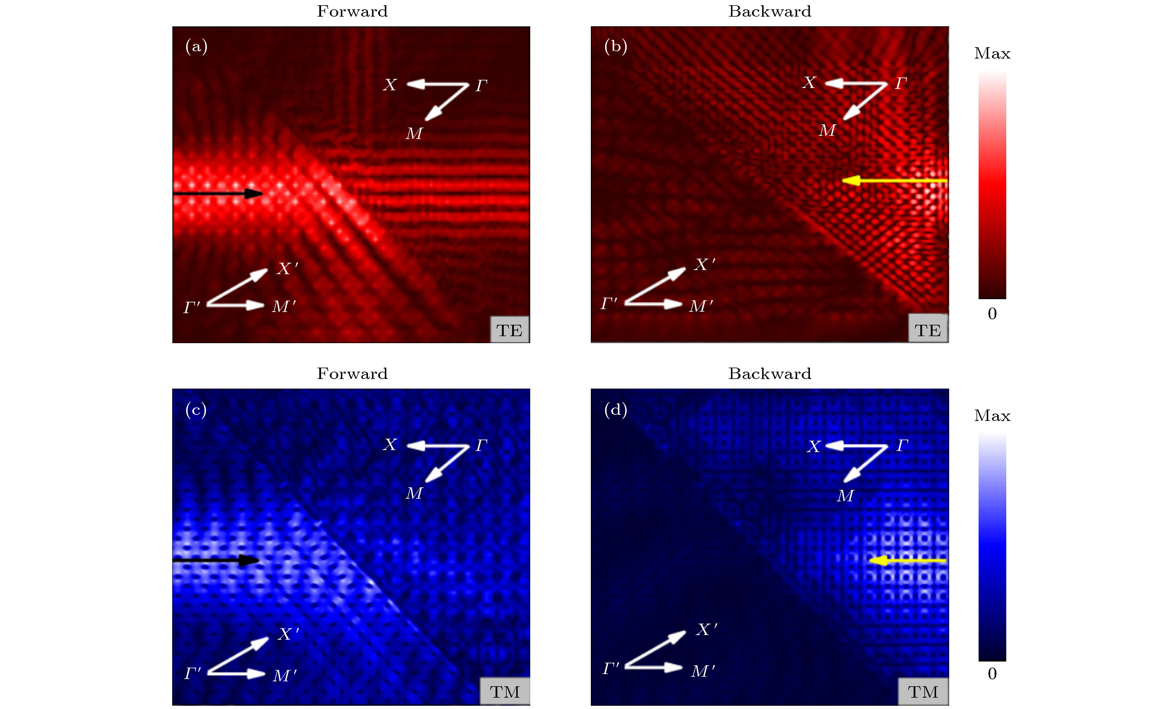 图 3 1550 nm波长处正向入射场强图和反向入射场强图 (a) TE偏振光正向; (b) TE偏振光反向; (c) TM偏振光正向; (d) TM偏振光反向


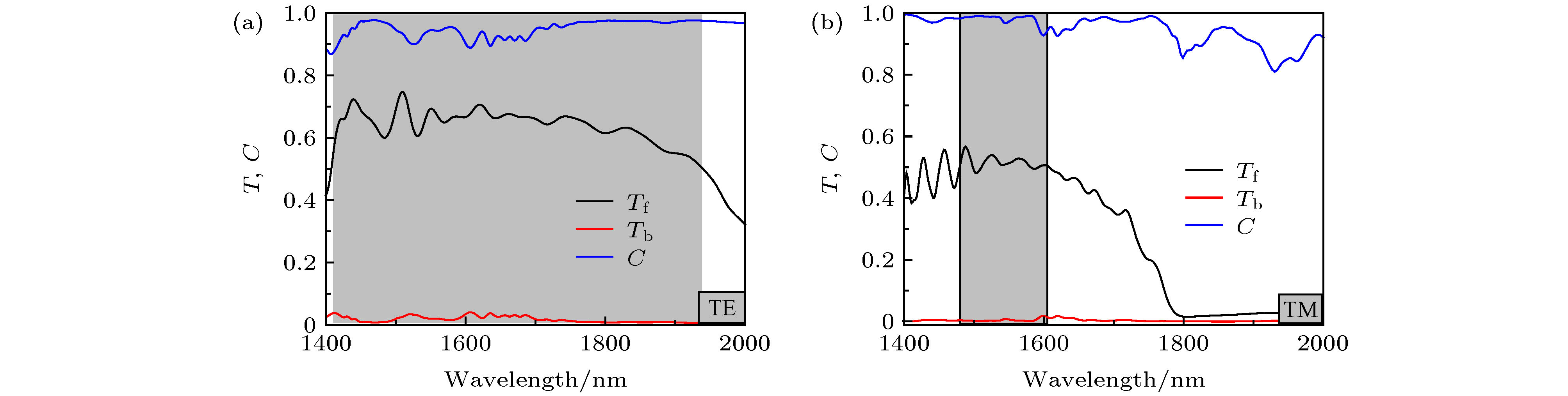 图 4 异质结构透射谱 (a) TE偏振光; (b) TM偏振光; 其中灰色区域表示结构工作带宽
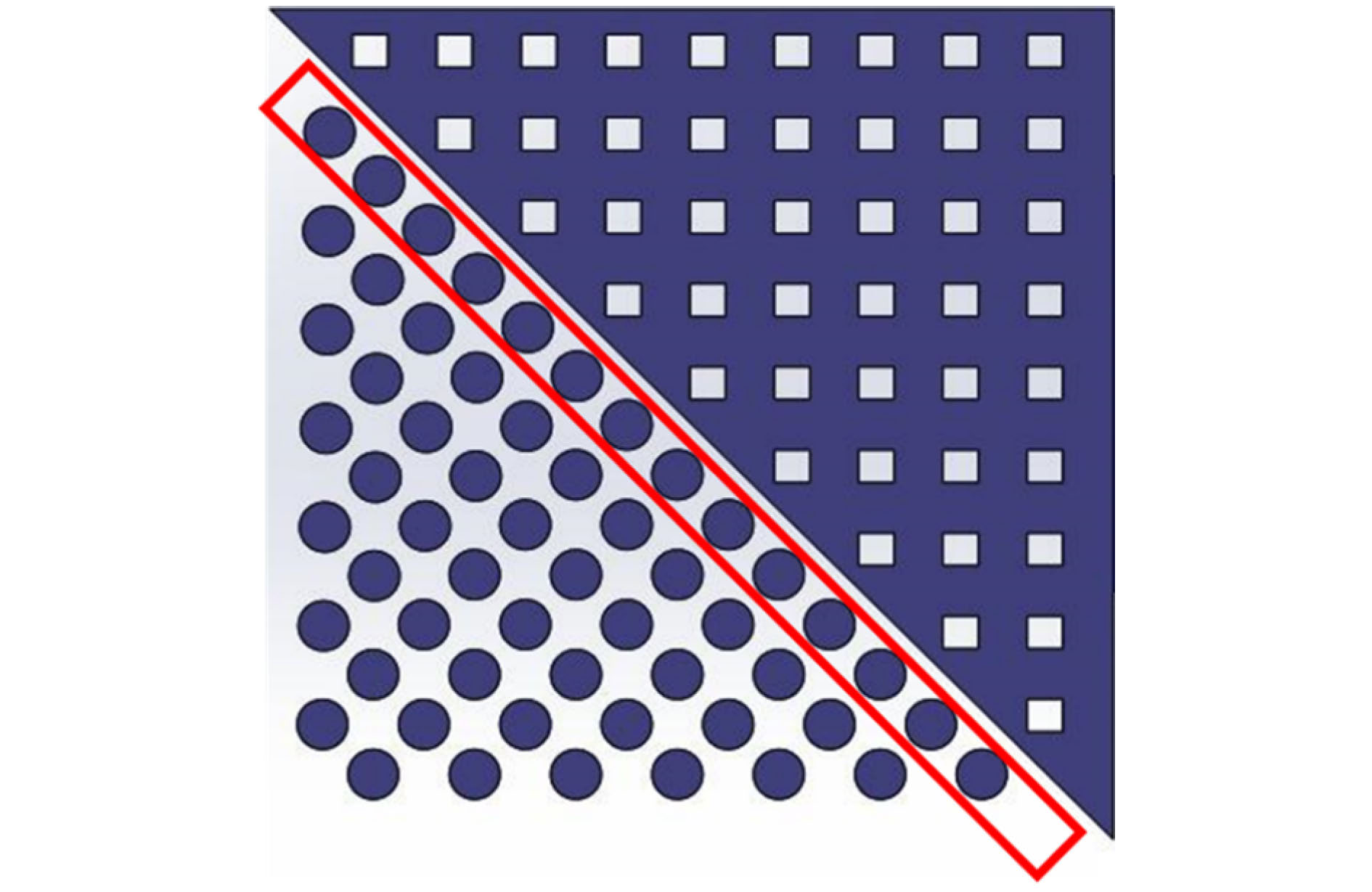 图 5 光子晶体异质结优化示意图, 其中被优化的光子晶体结构通过红色长方形标注
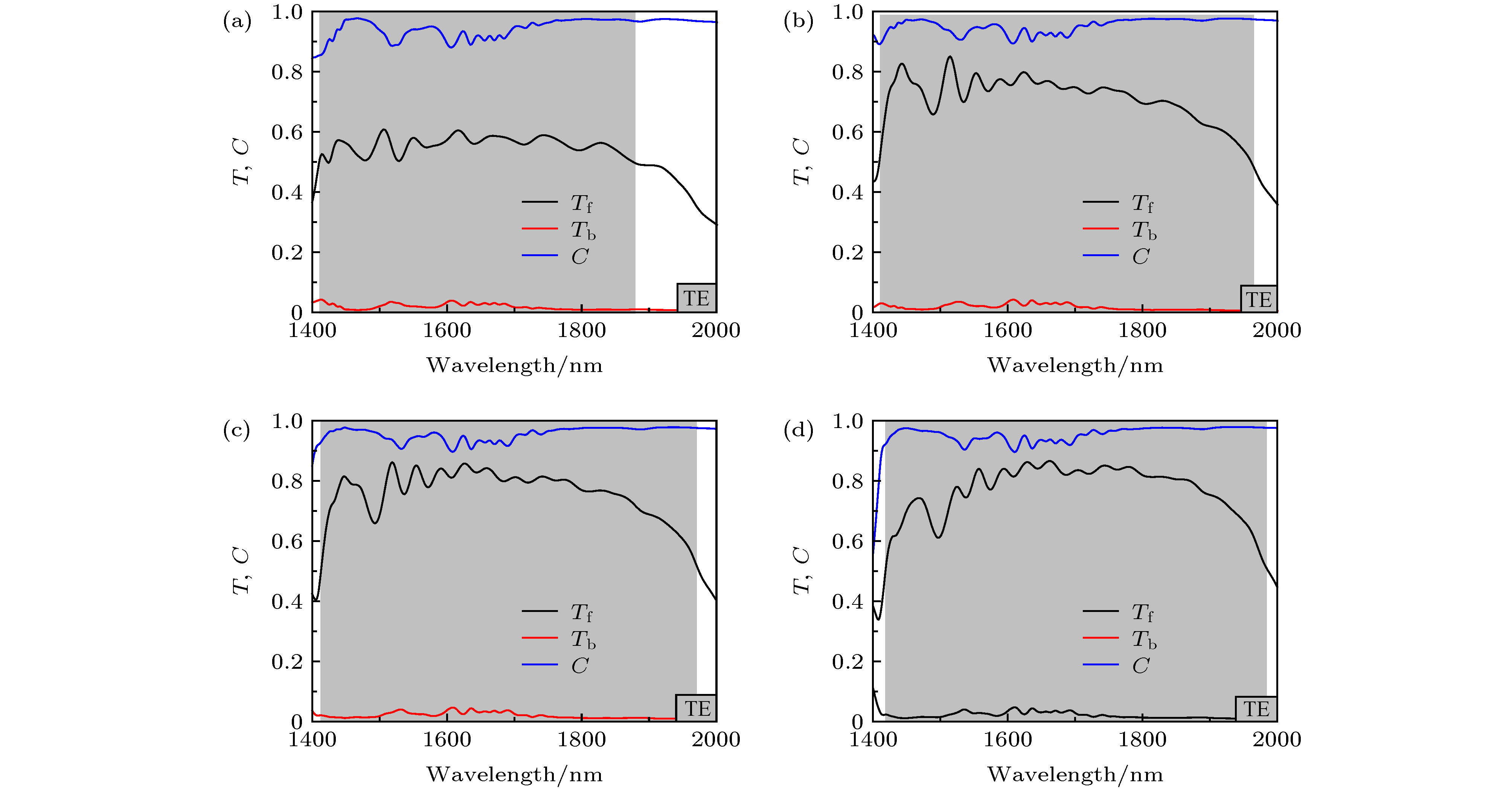 图 6 异质结构界面处PhC 1不同半径硅圆柱TE偏振光透射谱 (a) R = 55 nm; (b) R = 65 nm; (c) R = 70 nm; (d) R = 75 nm