全文HTML
--> --> -->太赫兹(terahertz, THz)波具有许多优异特性, 比如: 能量需求低、穿透衰减小、信噪比高、对生物大分子拥有强吸收和谐振特性等[20]. 与其他波段的电磁波相比, THz波具有直接探测生物分子信息的能力, 它在药品生产的监控、生物大分子的光谱识别[21]等方面具有巨大的应用潜力. 目前, 对支持混合等离子体模式的混合等离子体太赫兹波导(hybrid plasmonic terahertz waveguide, HPTWG)的研究具有良好的应用前景. 由于THz波的频率占据微波和红外之间, HPTWG可以实现低损耗微米级传播及较高的模场限制[22]. 虽然长程太赫兹混合等离子体(long-rang hybrid THz SPPs, LR-HTSPPs)波导减少了传播损耗, 实现了厘米级的传播长度, 但其束缚能力较弱[23].
为了更好地权衡模式束缚和传播长度之间的相互关系, 本文研究了一种对称双楔形太赫兹混合表面等离子体波导(wedge-to-wedge THz hybrid SPPs waveguide, WWTHSW)结构. 利用有限元方法(finite element method, FEM)研究了WWTHSW的模式特性和传输特性及其随波导结构尺寸变化的规律, 并分析了两条平行WWTHSW间的耦合特性. 最后, 我们对比了WWTHSW与对称微楔形太赫兹混合等离子体(hybrid THz microwedgeSPPs, HTMWSPPs)波导和对称型蝴蝶结太赫兹混合等离子体(hybrid THz bow-tie SPPs, HTBTSPPs)波导的性能.

 图 1 WWTHSW示意图 (a)三维图; (b)截面图
Figure1. Schematic diagram of the proposed WWTHSW: (a) 3D diagram; (b) cross-section.
为了定量分析HPTWG的模式和传输特性, 通常用有效折射率(neff)、传播长度(Lp)、归一化模场面积[17](A)、品质因数[26] (figure of merit, FOM)以及模式分布特性[2] (the mode character, MC)等参数衡量其特性.
传播长度Lp为
A定义为Am/A0. 其中: A0 = λ2/4表示自由空间中的衍射限制面积; Am为有效模场面积, 反映波导对模式的束缚能力, 定义为
为综合衡量波导的传输特性, 定义品质因数为
为描述混合等离子体波导模式中SPPs模式和波导模式之间的差异, 引入模式特性(MC):
本文采用FEM对太赫兹频段的模式特性和传播特性进行研究. 使用商用ComsolMultiphysics软件中的波动光学模块, 模型采用散射边界条件, 仿真时的模型外层区域宽度均设置为2λ, 应用非均匀三角网格进行剖分并设置最小单元网格大小为d/2, 由于Ag层内几乎没有场分布, 因此, d/2能够保证模型计算的收敛性的精度.
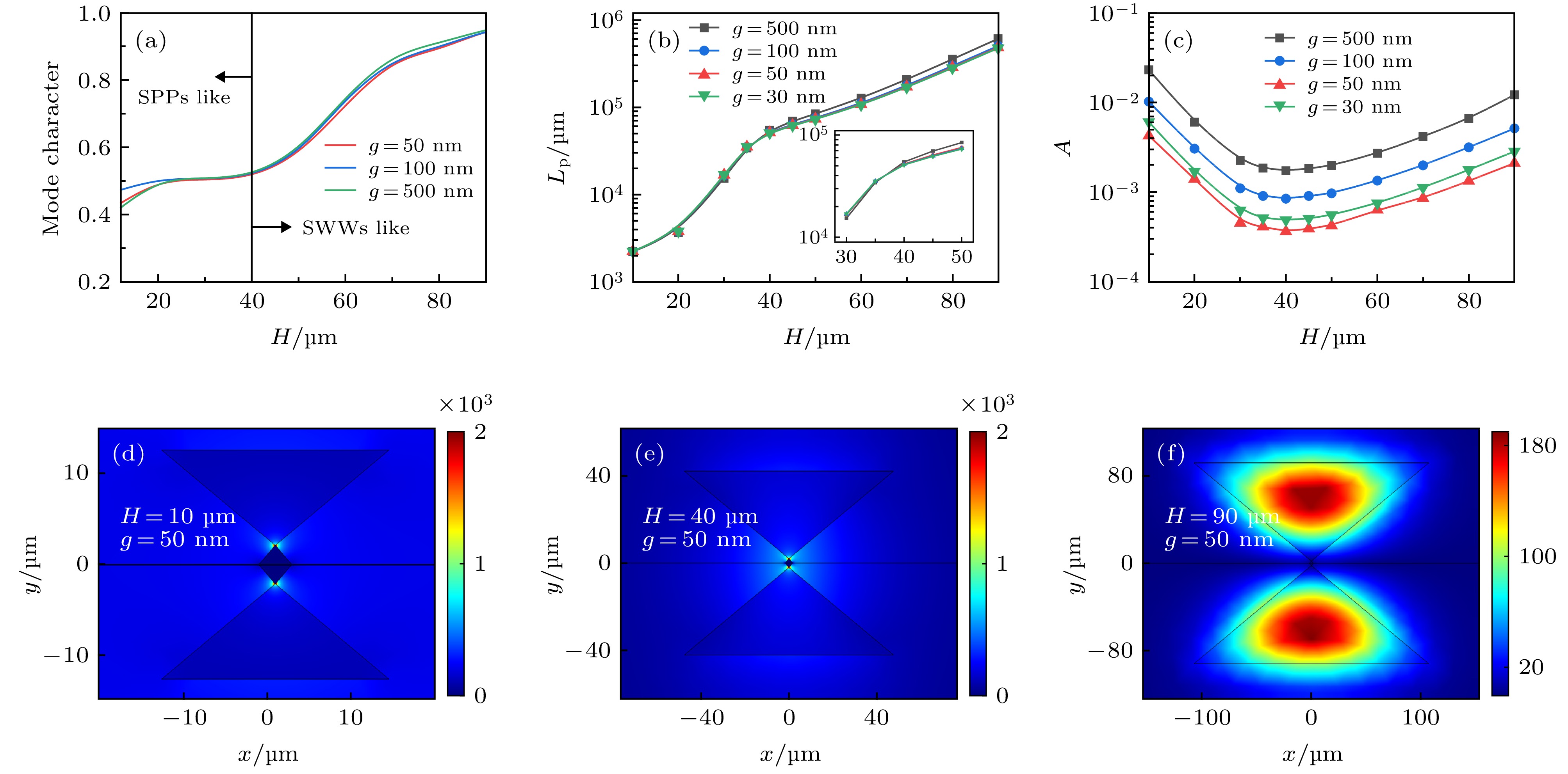 图 2 不同H和g时, WWTHSW的模式分析 (a) MC, (b) Lp, (c) A; 模场分布: (d) [H, g] = [10, 0.05] μm, (e) [H, g] = [40, 0.05] μm, (f) [H, g] = [90, 0.05] μm
Figure2. Modes analysis of the WWTHSW with different H and g: (a) MC, (b) Lp, and (c) A;and normalized EM energy density distributions: (d) [H, g] = [10, 0.05] μm; (e) [H, g] = [40, 0.05] μm; (f) [H, g] = [90, 0.05] μm.
从图2(c)可以看出, 对于相同的g, A随着H的增加而先减小再增大, H约40 μm处A达到最小值. 对于较小的SWWs(H小于40 μm), 混合模式主要由SPPs模式决定(MC < 0.5), 观察归一化能量密度分布图2(d)可发现, 该模式约束相对较弱. 当楔形波导的尺寸增大时(H大于40 μm), WWTHSW模式表现为低损耗SWWs模式(MC > 0.5), 大多数模式能量主要集中在高介电常数的SWWs芯部(如图2(f)), 从而导致模式面积增大. 在H = 40 μm时(MC = 0.5), 波导模式介于SWWs和SPPs模式之间, 处于一种临界状态, 同时具有SWWs和SPPs的模式特性, 此时模式面积A有最小值. 当H不变, A随着g的增大而增大, 这是由于g的增大使得模式能量分布逐渐远离Ag表面, 波导模式能量更加分散, A随之增大, 变化范围从3.62 × 10⁻⁴到3.69 × 10⁻³. 因此, 本文以下的研究中, 选择H = 40 μm, g = 50 nm, 此时, Lp为51.5 × 103 μm, A为3.62 × 10⁻⁴. 与文献[23]提出的LR-HTSPPs波导相比, Lp增大将近3倍, 而A减小1个数量级.
SWWs的α和θ也是影响WWTHSW模式性能的重要几何参数. 传播长度Lp随α和θ变化的规律如图3(a)所示, 对于任意θ, Lp随着α的增大而增大. 当α < 70°时, θ的变化对Lp几乎没有影响; 而当α > 70°时, Lp随着θ的增大而减小. A随α和θ的变化关系如图3(b)所示, 对于任意θ, A随着α的增大先减小再增加, 在α = 100°附近存在最小值. 如图3(b)的插图所示, 当α = 100°时, A也随着θ的增大先减小再增加. 图3(c)给出在θ = 80°时, 不同α的WWTHSW的归一化能量密度分布图. 当α = 40°和100°时, 波导模式以SPPs模式为主, 电磁场能量主要集中在Si楔形角与Ag楔形角之间, α增大, 模场能量逐渐远离金属表面, 欧姆损耗减小, 从而使Lp增大; 此时, 模式能量更加集中, A反而减小. 当α = 140°时, 模式以SWWs为主, 模式能量主要集中在SWWs内, 导致欧姆损耗减小, Lp增大, 模场能量无法限制在交界面, 从而使A也增大. 图3(d)给出在α = 100°时, 不同θ的WWTHSW的归一化能量密度分布图. 此时, 波导模式以SPPs模式为主, 随着θ从40°增加到80°再到140°, 模场能量与金属楔形的接触面积不断扩大, Ag引入的欧姆损耗增加, Lp减小. 当θ = 80°时, 模场能量更集中于双楔形之间, A达到最小值3.62 × 10⁻⁴, 此时传播长度为5.14 × 104 μm. 在本文以下研究中, 选用参数θ = 80°, α = 100°.
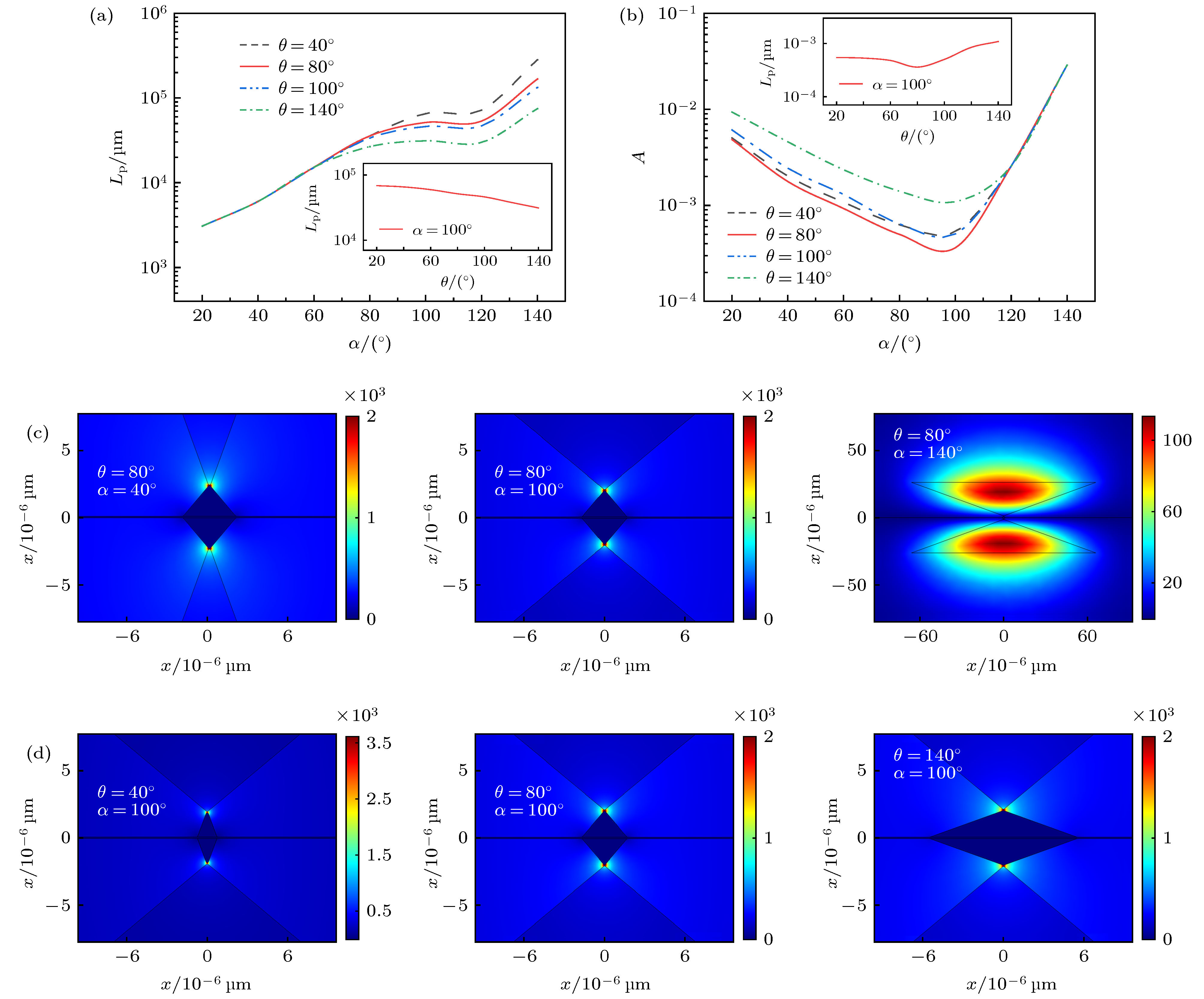 图 3 不同α和θ时, WWTHSW的模式分析 (a) Lp, (b) A; (c)模场分布随α的变化(θ = 80°); (d)模场分布随θ的变化(α = 100°)
Figure3. Modes analysis of the WWTHSW with different α and θ, (a) Lp, (b) A; and normalized EM energy density distributions: (c) with different α at a fixed θ of 80°, (d) with different θ at a fixed α of 100°.
图4(a)和(b)给出WWTHSW的Lp和A随着d和h的变化规律. 由图4可知, Lp和A随着d的增加而略微减小. 当d不变, h = 0时, Lp和A比h = 2 μm和5 μm时大. 结果表明, 增加Ag楔形结构(h = 2 μm和5 μm)后的波导相比于没有增加Ag楔形结构(h = 0)时的Lp略有减小, 但却具有更好的模场限制能力. 从图4(c)中的归一化能量密度分布可以看出, 当h为2 μm和5 μm时, 光场全部被限制在超深亚波长区域内, 从而减小了有效模场面积; 而在h = 2 μm和h = 5 μm时的微米边缘的模式轮廓差几乎可以忽略不计. 对于h = 2 μm, WWTHSW的横向模式宽度W = 0.01 μm(W, 其定义为能量密度衰减到其峰值的1/e的全宽度[17]), 相比于h = 0时横向波导模式的W = 1.2 μm, 减小12倍. 本文以下的研究中, 选用d = 100 nm, h = 2 μm.
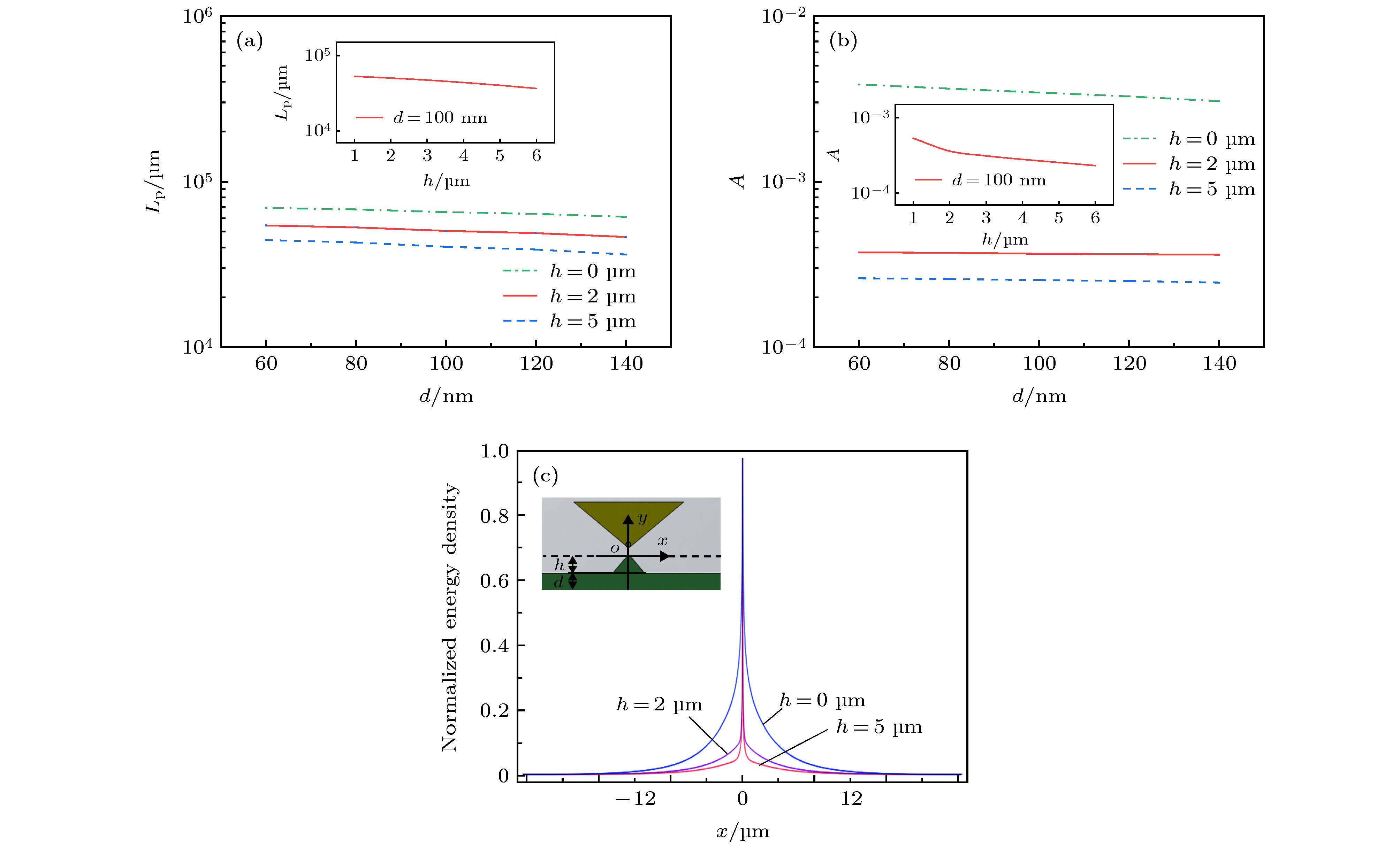 图 4 不同d和h时, WWTHSW的模式分析 (a) Lp、(b) A; (c)沿x方向的归一化能量密度
Figure4. Modes analysis of the WWTHSW with different d and h, (a) Lp, (b) A, and (c) normalized EM energy density.
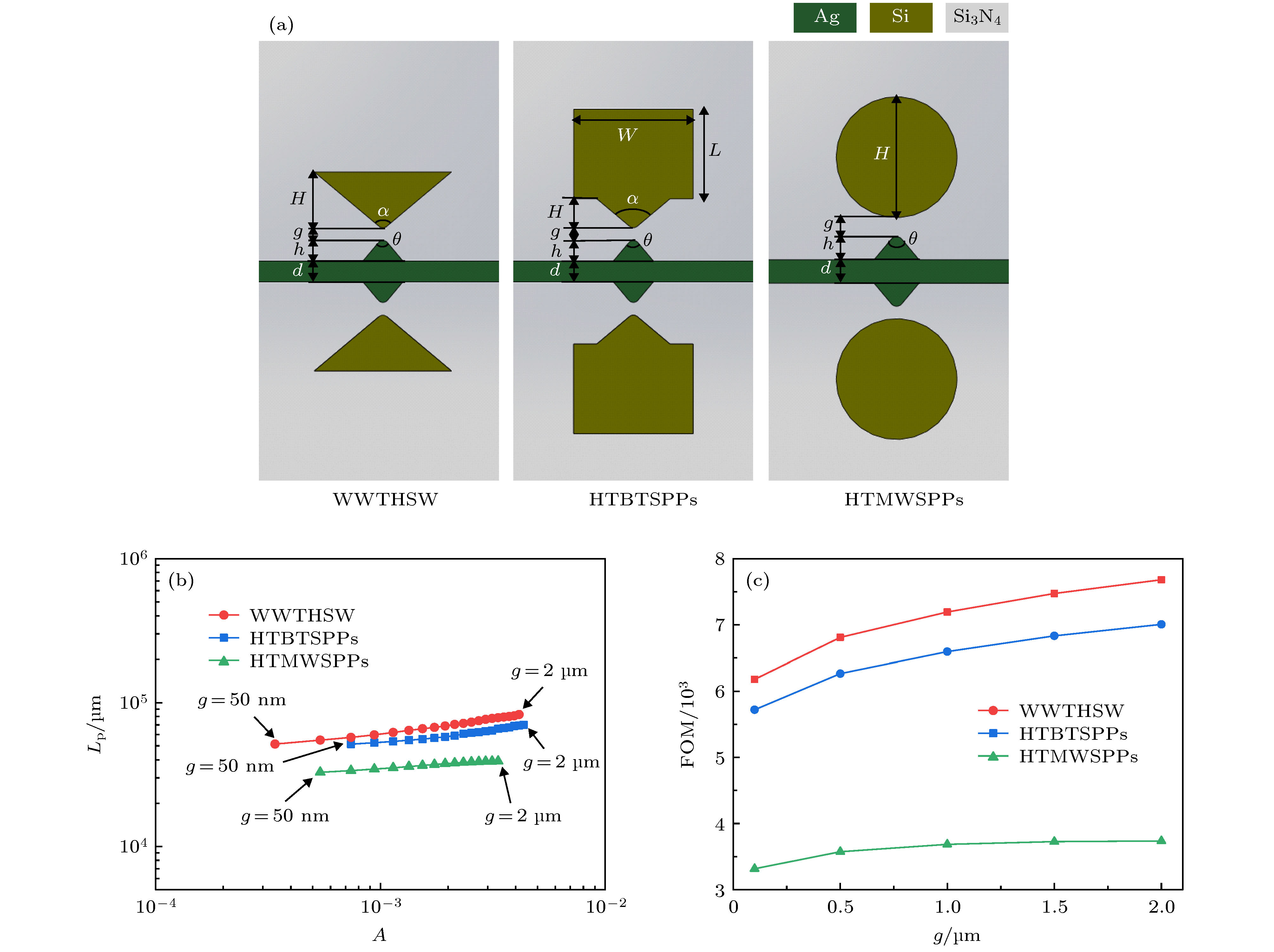 图 5 不同波导性能比较 (a) WWTHSW, HTMWSPPs和HTBTSPPs波导的截面图; (b) WWTHSW, HTMWSPPs和HTBTSPPs波导的A与Lp关系图; (c)品质因数
Figure5. Performance comparison of the WWTHSW, HTMWSPPs and HTBTSPPs wavguide: (a) cross-section views; (b) the relationship between A and Lp; and (c) FOM with different parameters.
图5(b)为Lp与A的相关性对比图. 在仿真中WWTHSW和HTMWSPPs波导选择最佳参数H = 40 μm, h = 2 μm, θ = 80°, α = 100°, g = 50 nm, d = 100 nm. HTBTSPPs波导选择最佳参数H = 10 μm, W = L = 30 μm. 由图5(b)可知, WWTHSW比HTMWSPPs波导和HTBTSPPs波导的Lp更长. 相比于HTMWSPPs波导, WWTHSW由于尖端场增强效应, 光场主要聚集在楔形波导的顶点附近[1], 具有更强的模场限制能力; 而相比于HTBTSPPs波导, WWTHSW没有矩形Si波导部分, 有利于模场能量的集中, 因此具有更小的模场面积. g在50 nm到2 μm范围内, WWTHSW的有效模场面积(Am = λ2/10280)相比于HTBTSPPs波导(Am = λ2/5405)减小近2倍, 相比于HTMWSPPs波导(Am = λ2/7407)减小近1.5倍. 在相同的有效模场面积Am = λ2/5405的情况下, WWTHSW的Lp为65×103 μm, 是HTMWSPPs波导(Lp = 54 × 103 μm)的1.2倍, 是HTBTSPPs波导(Lp = 33 × 103 μm)的2倍. 而在相同的传播长度Lp = 51 × 103 μm的情况下, WWTHSW的有效模场面积(Am = λ2/10280), 比HTBTSPPs波导(Am = λ2/4422)减小2倍. 由图5(c)可知, 相比于HTBTSPPs波导、HTMWSPPs波导, WWTHSW品质因数更好. 因此, WWTHSW相比HTBTSPPs波导、HTMWSPPs波导在相似的传播长度下, 具有更强的模场限制能力和更好的品质因数.
为了分析WWTHSW的耦合特性, 构建两根间距为D的平行WWTHSW, 如图6(a)所示. 通常, 波导的耦合特性由波导的耦合长度Lc = π/(βs – βa)来衡量, 其中βs和βa分别是两个相邻波导的对称和反对称模的传播常数[28].
 图 6 波导耦合特性分析 (a)平行波导三维结构示意图; (b)耦合长度随D的变化; (c)最大传输功率随D的变化
Figure6. Coupling characteristic of waveguides: (a) schematic diagram parallel waveguides; (b) Lc versus the separation between the two waveguides; (c) the maximum transfer power (Pmax) as a function of distance D.
WWTHSW、HTBTSPPs和HTMWSPPs波导的Lc随两条平行波导中心间距D的对应关系如图6(b)所示. 在仿真中, 采用上述最佳参数, H = 40 μm, h = 2 μm, θ = 80°, α = 100°, g = 50 nm, d = 100 nm. 图6(a)为WWTHSW在D = 12 μm参数下的对称和反对称模式的归一化能量密度分布. 从图(6)中可以看出, WWTHSW的Lc高于HTBTSPPs波导、HTMWSPPs波导的Lc, 这种差异随着间隔D增大变化更加明显. 当D = 12 μm时, HTMWSPPs波导的Lc为2195 μm, 而WWTHSW的Lc为2749 μm, 是HTMWSPPs波导的1.2倍. 当D = 20 μm时, HTMWSPPs波导的Lc为20361 μm, WWTHSW的Lc为28896 μm, 是HTMWSPPs波导的1.5倍. 该结果表明, 在相同的Lc下, 与HTBTSPPs波导和HTMWSPPs波导相比, 本文提出的WWTHSW可显著降低串扰, 这对于高度集成的光子器件来说是一个极大的优势.
另外, 波导耦合过程中的传播损耗是不可避免的, 因此, 用最大功率传递[29](Pmax)表明波导损耗特性,
图6(b)为WWTHSW、HTMWSPPs波导和HTBTSPPs波导的Pmax与间距D的关系图. 从图6(b)可以看出, 对于相同的最大功率传输Pmax, 两个HTWWSPP波导之间的间隔距离D小于两个HTBTSPPs波导和HTMWSPPs波导之间的间隔距离D. 忽略波导间串扰(Pmax < 10–3)[29] 时, WWTHSW最小间隔距离D为15.8 μm, HTBTSPPs波导最小间隔距离D为17.3 μm, HTMWSPPs波导最小间隔距离D为18.6 μm; WWTHSW最小间隔距离相比于HTBTSPPs波导最小间隔距离减小1.5 μm, 相比于HTMWSPPs波导最小间隔距离减小2.8 μm. 结果表明WWTHSW能够实现更高的封装密度.
