全文HTML
--> --> -->文献[17]通过采用带阻型FSS取代2 × 2天线阵的金属地板, 在4.0—16.5 GHz范围内有效降低了天线阵的RCS. 文献[18]通过利用多种单元构造新型的PRS, 并以共地板共基板的方式将其加载在2 × 2贴片阵列周围, 在保持辐射特性基本不变的情况下, 在6.0—7.6 GHz和9.5—26.0 GHz范围内实现了天线的RCS减缩. 文献[19]将有效相位差的EMS排布在2 × 2微带天线阵周围, 在6.2—7.3 GHz范围内有效减缩了天线RCS. 2018年, Zhang等[20]将两种AMC结构放置在微带天线阵下方, 并利用编码思想优化布阵, 在6.0—13.4 GHz宽带范围内实现了RCS减缩. 尽管已有较多文献通过加载EMS实现了天线阵的RCS减缩, 但在设计时, EMS单元和天线阵设计各自独立, 且所研究的对象大多偏向于小规模阵列, 对于更大规模阵列天线的RCS缩减问题研究较少.
本文针对较大规模微带天线阵的辐射与散射难以同时兼顾的难题, 在设计天线单元时, 引入EMS的设计思想, 单元结构既作为天线单元, 又作为EMS单元. 在矩形贴片天线研究的基础上, 通过结构优化演变设计了另一种与原始天线单元工作在相同模式、相同频段的天线单元, 并与其形成有效相位差. 通过将两种单元以棋盘形式布阵组成4 × 4天线阵, 在y极化下, 实现了基于相位对消原理的RCS减缩, 在x极化下, 采用加载匹配负载的方式实现了基于吸波原理的RCS减缩. 由于两种天线单元在辐射性能上具有较好的一致性, 使得组合天线阵同样具有优良的辐射性能.


 图 1 单元三维结构示意图 (a) 单元1; (b) 单元2
Figure1. Geometry of (a) element 1 and (b) element 2.
在主从边界条件和Floquet端口激励下, 对单元1作为EMS1的反射特性进行仿真, 结果如图2所示. 在x极化下, EMS1加载

 图 2 匹配负载对EMS1反射特性的影响 (a) 反射幅度; (b) 反射相位
Figure2. Reflection characteristics with and without matching load: (a) Reflection magnitude; (b) reflection phase.
 图 3 不同参数对EMS1反射特性的影响 (a) l1对反射幅度的影响; (b) l1对反射相位的影响; (c) s1对反射幅度的影响; (d) s1对反射相位的影响; (e) w1对反射幅度的影响; (f) w1对反射相位的影响
Figure3. Effects of various parameters on reflection performance: Effects of l1 on (a) reflection magnitude and (b) phase; effects of s1 on (c) reflection magnitude and (d) phase; effects of w1 on (e) reflection magnitude and (f) phase.
根据以上分析, 为了使由两种单元组合的阵列在y极化入射波下实现基于相位对消原理的RCS减缩, 在矩形贴片上开口设计单元2是较好的方法, 其目的在于减小窄边w1在y方向上的等效长度, 使y极化下的反射相位向高频移动, 从而与EMS1之间形成有效相位差. 故通过在矩形贴片上开弧形缺口, 分析开口对天线反射系数及对y极化入射波下反射相位的影响, 结果如图4所示. 由图4可知, 开口后天线相对带宽几乎不变, 工作频带稍向低频移动, 而在y极化下的反射相位则向高频移动, 故开口有利于相位向高频偏移以便与原始单元之间形成有效相位差. 之后通过优化天线矩形辐射贴片的长边、窄边及开口的深浅r和馈电点位置s2, 得到了既使E2与E1工作在相同频段, 又使EMS2在y极化下与EMS1存在有效相位差的最终结构, 如图1(b)所示. 具体参数如下: l2 = 12.0 mm, w2 = 14.3 mm, s2 = 2.3 mm, r = 3.8 mm.
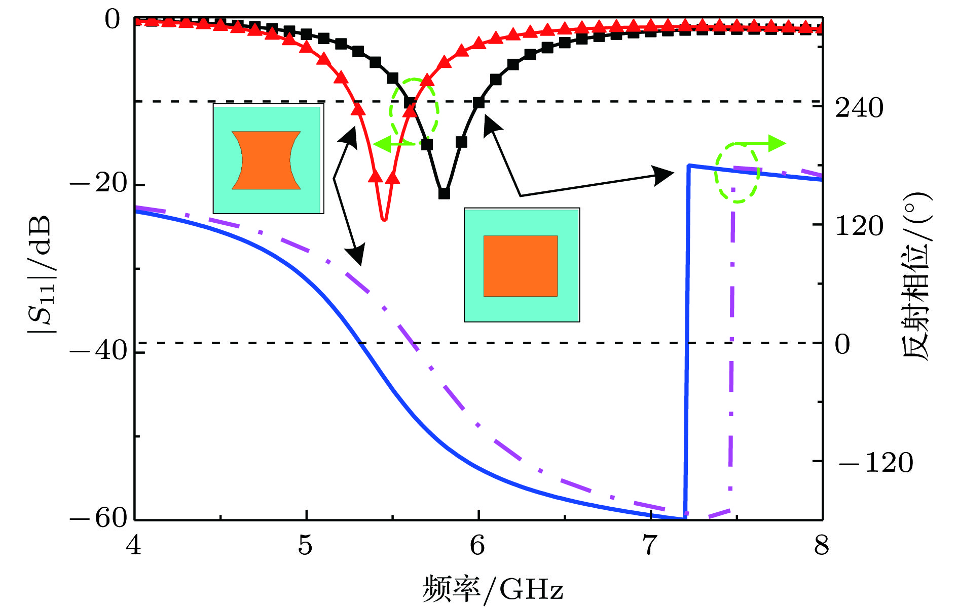 图 4 弧形缺口对天线|S11|及y极化下反射相位的影响
Figure4. Influences of arc-shaped structure on reflection coefficient |S11| and reflection phase.
图5(a)给出了优化后两种天线的|S11|曲线, E2仍在5.8 GHz处谐振, 谐振带宽(5.2%)相较于E1 (6.9%)略有缩减. 图5(b)给出了在谐振点5.8 GHz的方向图, 二者无论是xoz面还是yoz面都近乎完全重合, 故E2与E1在辐射性能上具有较好的一致性. 当两种单元作为EMS时, 其对应的反射特性如图6所示. 在x极化下, 二者均存在较高的吸波率, 相位曲线差别不大, 不存在有效相位差. 而在y极化下, 都近乎全反射, 但在5.5—6.9 GHz存在有效相位差, 基本满足相位对消的条件.
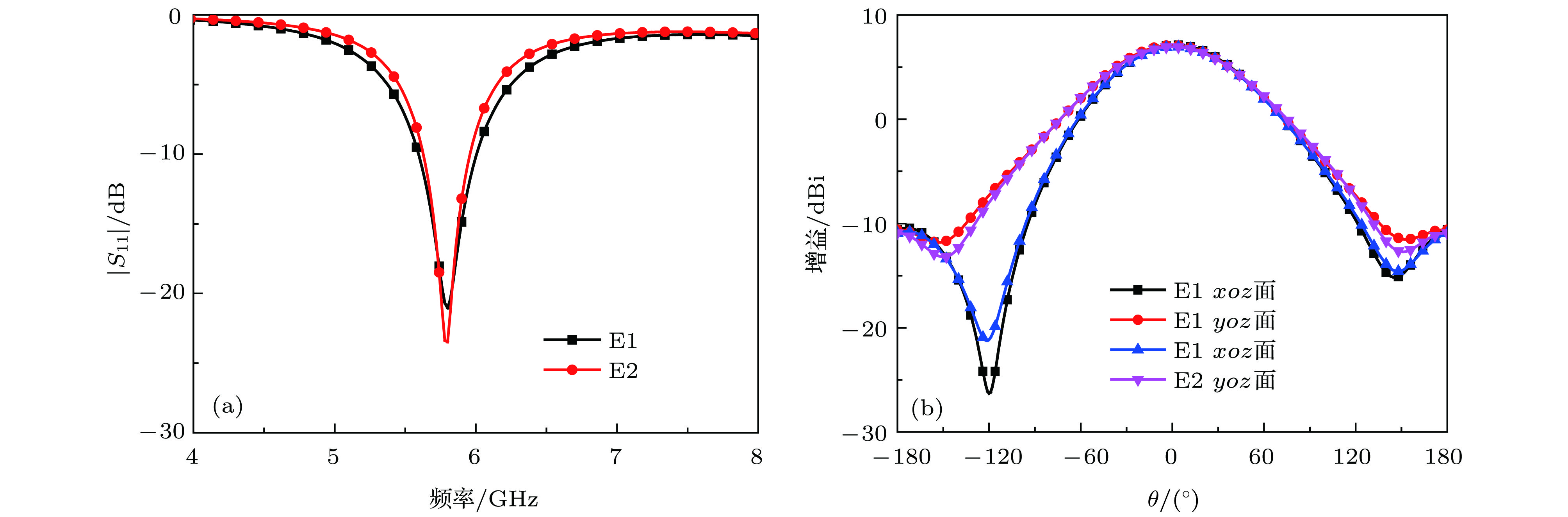 图 5 天线单元辐射特性 (a) |S11|; (b) 方向图
Figure5. Radiation properties of two elements: (a) Reflection coefficients |S11|; (b) two-dimensional radiation patterns at 5.8 GHz.
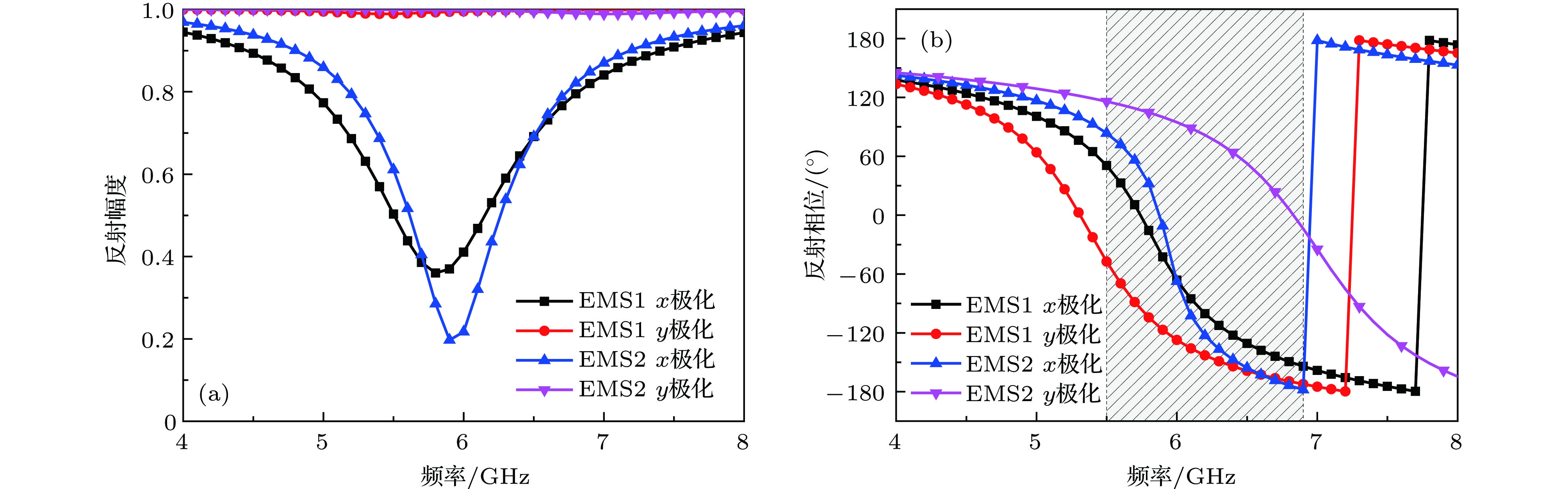 图 6 EMS反射特性 (a) 反射幅度; (b) 反射相位
Figure6. Reflection characteristics of two elements: (a) Reflection magnitude; (b) reflection phase.
为了进一步说明这种开口方式的机理, 图7给出了两种单元在辐射边界条件下的表面电场分布和在主从边界条件下的表面电流分布. 由图7(a)和图7(b)可知, E1辐射贴片两窄边电场方向相反, 开缺口后, E2窄边两端的电场方向仍互为反向, 天线的主模激励TM10模没有发生改变. 在y极化波照射下, EMS1和EMS2在各自零反射相位频点(5.24和6.86 GHz)的表面电流分布如图7(c)和图7(d)所示, 由于EMS2金属贴片在y方向上的实际物理尺寸减小, 使电流流动路径变短, 因此EMS2的谐振频率向高频偏移, 从而与EMS1之间形成了有效相位差.
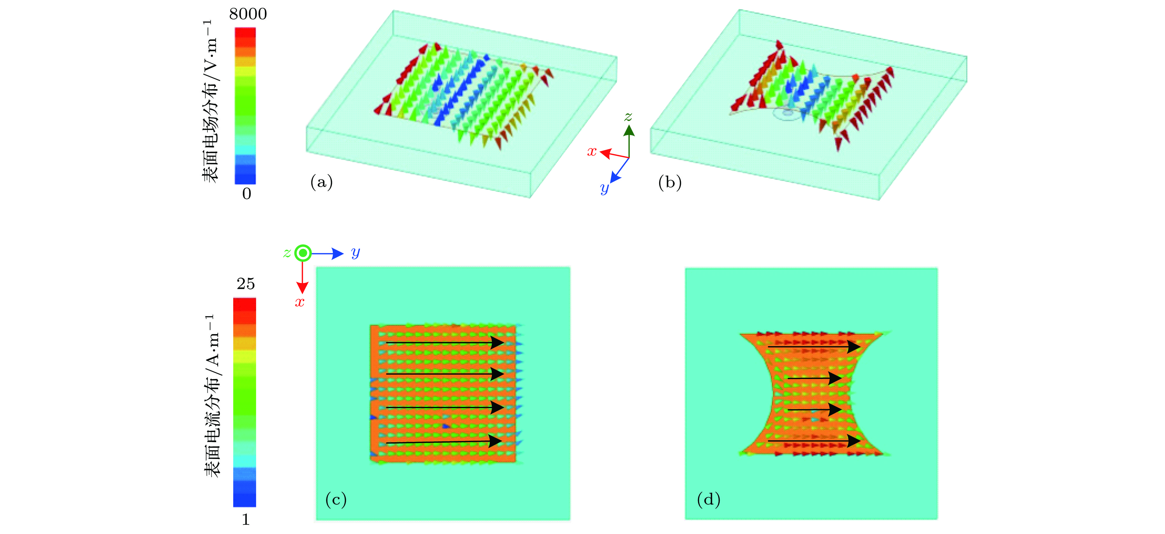 图 7 表面电场与电流分布 (a) E1在5.8 GHz的表面电场分布; (b) E2在5.8 GHz的表面电场分布; (c) EMS1在5.24 GHz的表面电流分布; (d) EMS2在6.86 GHz的表面电流分布
Figure7. Surface E-field distributions at 5.8 GHz of (a) E1 and (b) E2; surface current distributions (c) at 5.24 GHz of EMS1 and (d) at 6.86 GHz of EMS2.
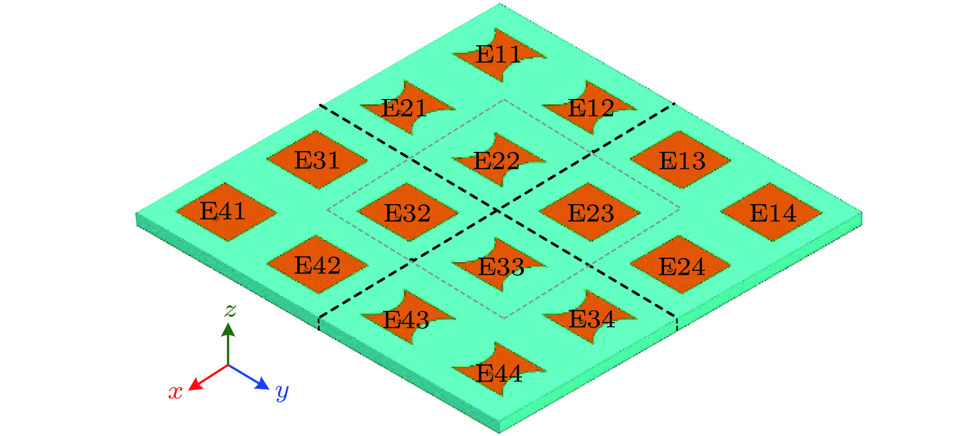 图 8 设计天线阵的模型示意图
Figure8. Schematic geometry of the proposed antenna array
取阵列中间四个单元作为对比, 即取E22, E23, E32, E33. 图9(a)给出了这四个天线单元的|S11|, 可以看出, |S11|曲线几乎重合, 均在5.8 GHz产生谐振. 图9(b)给出了增益特性曲线, 可以看出, 阵列在工作频带内, 增益始终在16 dBi以上. 图9(c)和图9(d)给出了在5.8 GHz的方向图, 可知在主瓣方向天线阵交叉极化远小于主极化. 以上分析验证了两种具有相同谐振模式, 且工作频带几乎相同的天线单元组合布阵后, 也拥有良好的辐射特性.
 图 9 仿真天线阵辐射性能 (a) |S11|; (b) 增益; (c) 5.8 GHz处xoz面辐射方向图; (d) 5.8 GHz处yoz面辐射方向图
Figure9. Simulated radiation properties of proposed antenna array: (a) Reflection coefficients |S11|; (b) gain; two-dimensional radiation patterns at 5.8 GHz for (c) xoz plane; (d) yoz plane.
图10给出了天线阵列的单站RCS, 并与等大小金属板的RCS比较. 在入射波垂直入射时, x极化下, 天线阵在谐振点5.8 GHz处具有较强的反射抑制, 相较于金属板, 在5.6—6.2 GHz范围内实现了6 dB以上的RCS减缩, 覆盖天线工作频段5.6—6.0 GHz. y极化下, 天线阵在5.5—7.0 GHz范围内实现了6 dB以上的RCS减缩, 相对带宽为24%. 在入射波斜30°照射下的镜像双站RCS如图11所示, x极化下, 所设计的天线阵在带内仍可有减缩6 dB以上, y极化下, 在5.5—7.0 GHz仍有5 dB以上的RCS减缩.
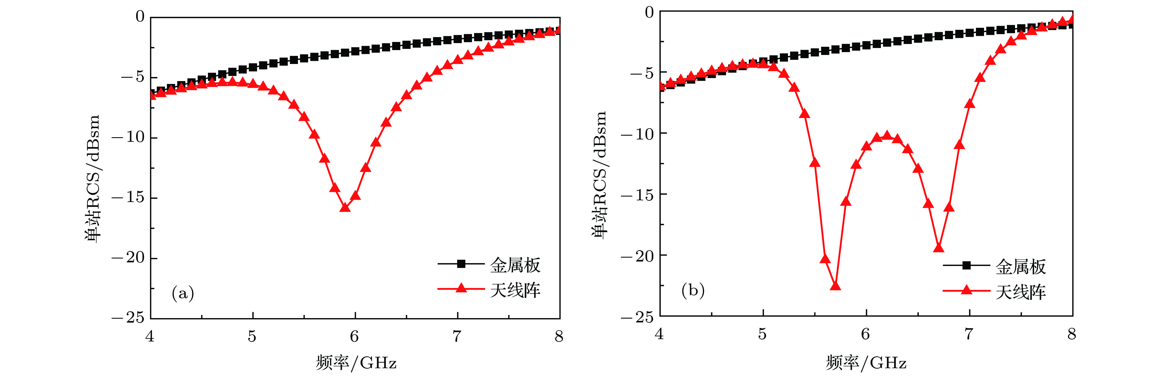 图 10 电磁波垂直入射时天线阵单站RCS (a) x极化; (b) y极化
Figure10. Simulated scattering properties of antenna array under normal incidence: (a) x-polarization; (b) y-polarization.
 图 11 电磁波斜30°入射时天线阵镜像双站RCS (a) x极化; (b) y极化
Figure11. Simulated specular scattering properties of antenna array for incident angle of 30°: (a) x-polarized incidence; (b) y-polarized incidence.
为了直观地说明两种极化下RCS减缩的机理不同, 图12给出了在入射波垂直入射时5.8 GHz处不同极化下的三维散射方向图. 可以看出, 设计天线阵在x极化下的反射波峰明显小于金属板, 在整个角域内的能量都得到了降低, 故在x极化下的RCS减缩是基于匹配负载的吸收. y极化下, 设计天线阵在

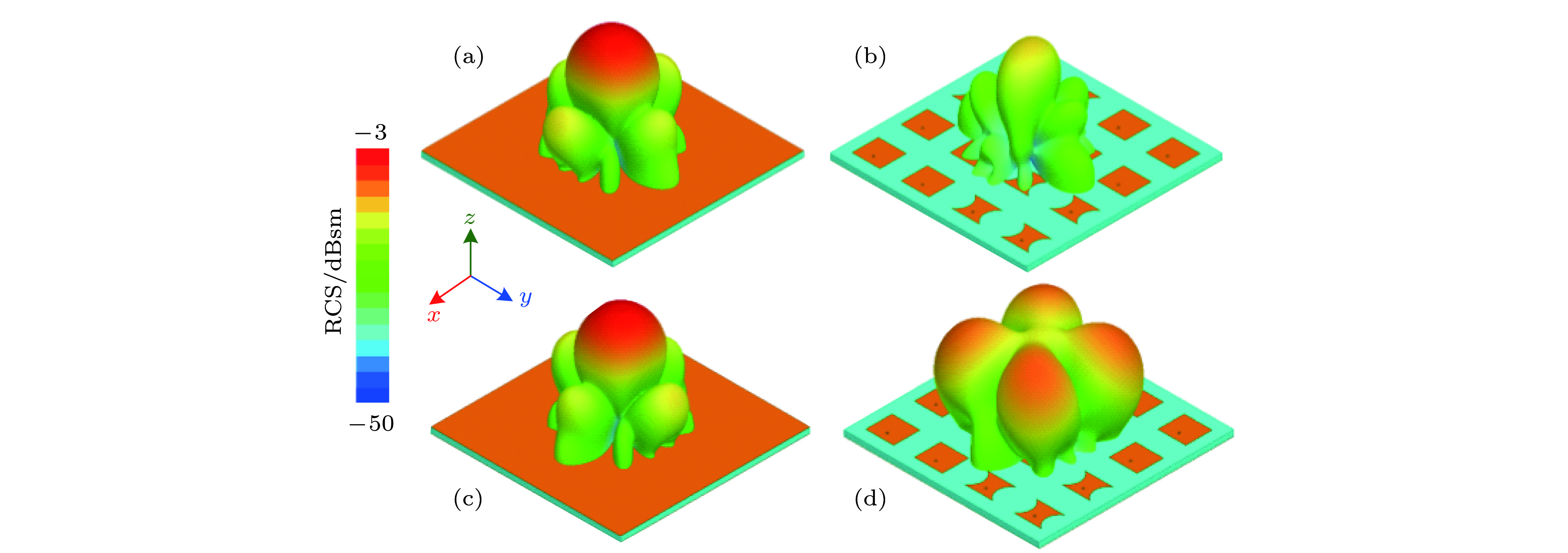 图 12 5.8 GHz处三维散射图 (a) x极化下金属板; (b) x极化下天线阵; (c) y极化下金属板; (d) y极化下天线阵
Figure12. Three-dimensional scattering patterns of total RCS at 5.8 GHz under x-polarized incidence for (a) metal board and (b) antenna array; under y-polarized incidence for (c) metal board and (d) antenna array.
基于以上分析可知, 设计天线阵具有较好的辐射和散射性能. 此外, 就本文所设计天线阵的辐散射性能和物理尺寸与其他文献[17—20]中报道的低散射微带天线阵进行了比较, 结果如表1所列, 表中

| 阵列规模 | 阵元间隔/$\lambda $ | 天线阵尺寸大小 | 天线阵相对带宽/% | 带内RCS减缩量 | RCS缩减相对带宽/% | |
| 文献[17] | 2 × 2 | 0.69 | 1.38$\lambda $ × 1.38$\lambda $ | 2.4 | 无减缩 | 122 |
| 文献[18] | 2 × 2 | 0.64 | 2.40$\lambda $ × 2.40$\lambda $ | 10.9 | 3 dB以上 | 126 |
| 文献[19] | 2 × 2 | 0.60 | 3.65$\lambda $ × 3.65$\lambda $ | 11.0 | 5 dB以上 | 93 |
| 文献[20] | 2 × 2 | 0.90 | 1.80$\lambda $ × 1.80$\lambda $ | 5.5 | 无减缩 | 69 |
| 本文 | 4 × 4 | 0.48 | 1.92$\lambda $ × 1.92$\lambda $ | 6.9 | 6 dB以上 | 59 |
表1本文所设计的低散射微带天线阵与文献[17?20]中的对比
Table1.Comparison between this work and other antenna arrays in Ref. [17?20].
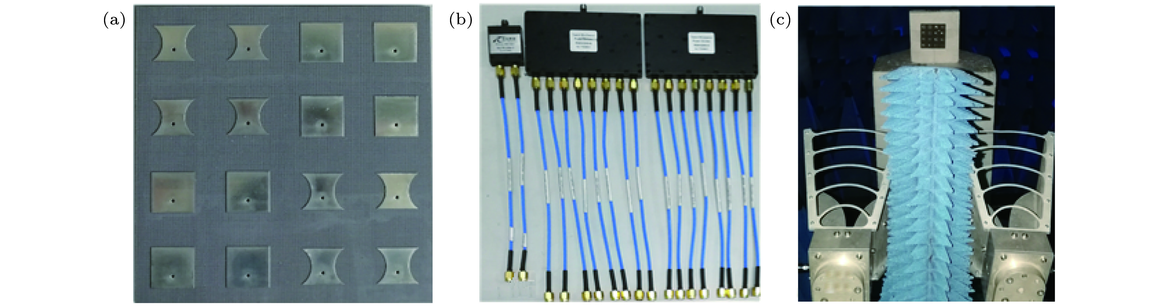 图 13 阵列天线实物及测试配置图 (a) 天线阵实物; (b) 功分器; (c) 散射测试环境
Figure13. Fabricated sample of antenna array and testing environment: (a) Sample; (b) one in two power divider RS2W2080-S and one in eight power dividers RS8W2080-S; (c) testing environment for scattering performance.
图14给出了实测的天线阵|S11|和在5.8 GHz处的方向图. 可以看出, 阵列单元均谐振在5.8 GHz处, 谐振带宽相差较小, 实测辐射方向图与仿真方向图近乎重合, 设计的天线阵列具有良好的辐射性能. 图15(a)给出了天线阵在垂直入射时相较于等大小金属板的RCS减缩量. x极化下, 天线阵在天线工作频带内实现了6 dB以上的RCS减缩, 最大减缩量达13.8 dB. y极化下, 天线阵在5.3—7.1 GHz范围内实现了6 dB以上的RCS减缩. 在斜入射30°时, 实测的镜像双站RCS如图15(b)所示, 天线阵在任意极化波斜入射时, 仍具有良好的反射抑制特性. 实测结果验证了设计方法的有效性.
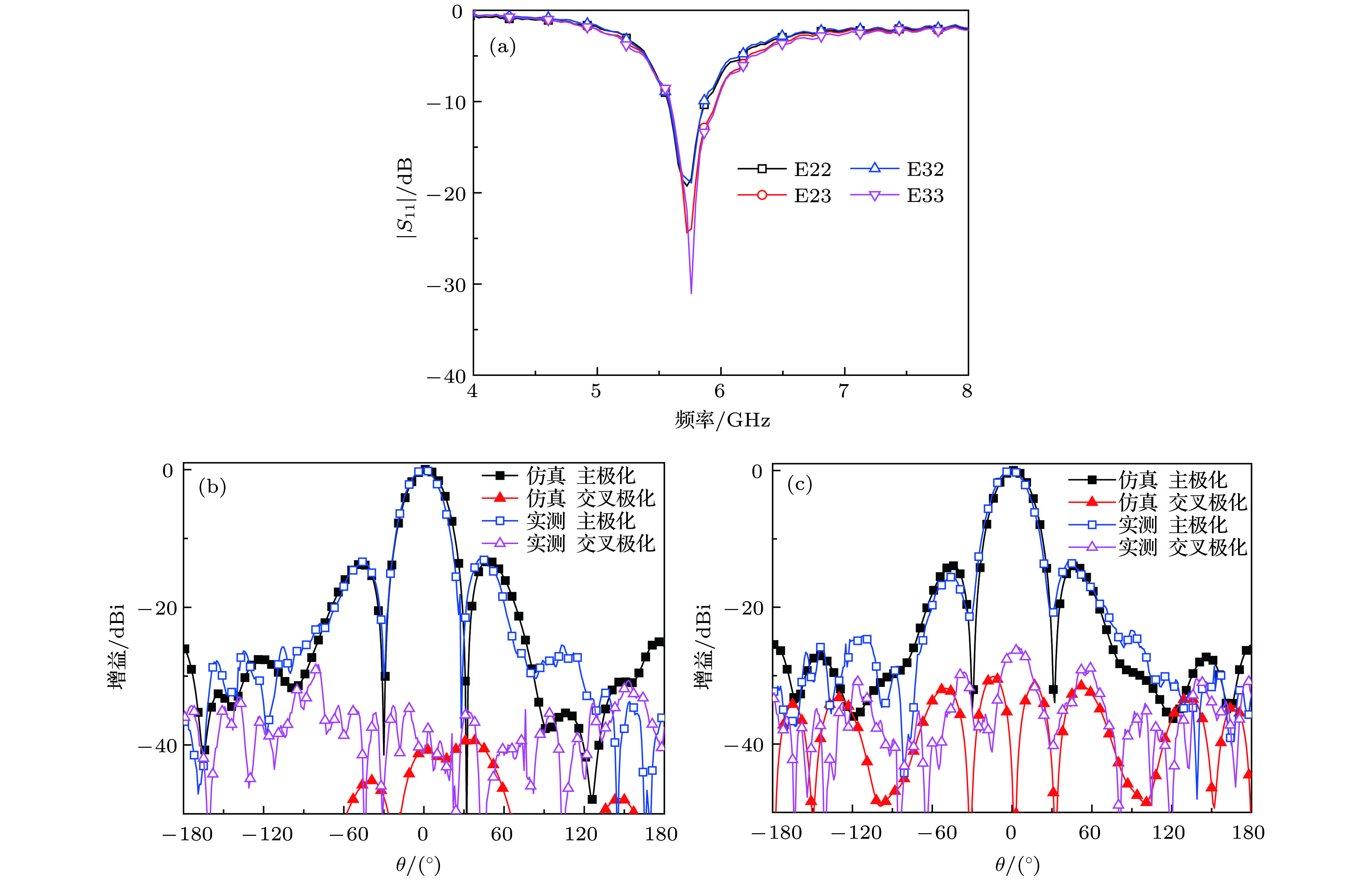 图 14 实测天线阵的辐射特性 (a) |S11|; (b) 5.8 GHz处xoz面辐射方向图; (c) 5.8 GHz处yoz面辐射方向图
Figure14. Measured radiation properties of antenna array: (a) Measured reflection coefficients |S11|; two-dimensional radiation patterns at 5.8 GHz for (b) xoz plane; (c) yoz plane.
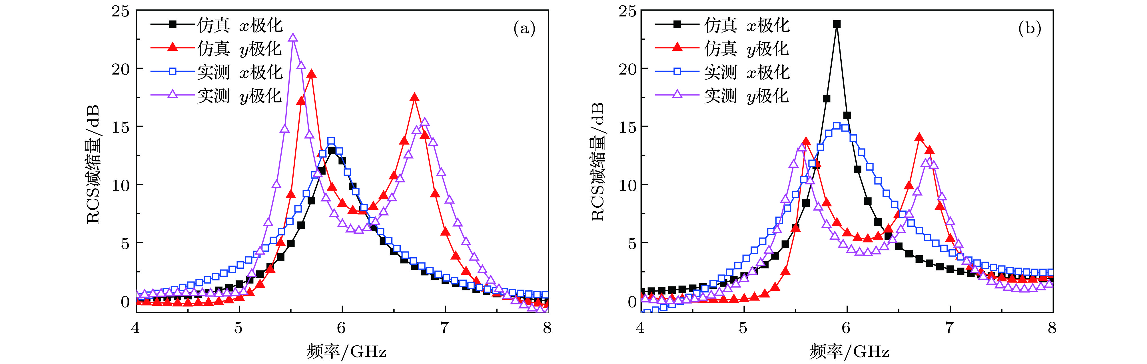 图 15 RCS减缩量 (a) 入射波垂直入射; (b) 入射波斜30°入射
Figure15. RCS reduction in contract to metal board for incident angles of (a) 0° and (b) 30°.
