 ,2)南京理工大学理学院, 南京210094
DYNAMICS MODELING, SIMULATION, AND CONTROL OF ROBOTS WITH FLEXIBLE JOINTS AND FLEXIBLE LINKS$^{\bf 1)}$
Fang Wuyi, Guo Xian, Li Liang, Zhang Dingguo,2)School of Science, Nanjing University of Science and Technology, Nanjing 210094, China通讯作者: 2)章定国, 教授, 主要研究方向: 柔性多体系统动力学与控制. E-mail:zhangdg419@mail.njust.edu.cn
收稿日期:2020-03-5接受日期:2020-03-30网络出版日期:2020-07-18
| 基金资助: |
Received:2020-03-5Accepted:2020-03-30Online:2020-07-18
作者简介 About authors

摘要
本文探究了铰柔性对机器人动力学响应和动力学控制的影响. 首先, 建立由$n$个柔性铰和$n$个柔性杆组成的空间机器人模型, 运用递推拉格朗日动力学方法, 得到柔性机器人系统的刚柔耦合动力学方程. 在动力学建模过程中, 除了考虑杆件的拉伸变形、弯曲变形、扭转变形以及非线性耦合变形对机器人系统动力学行为的影响, 还考虑了铰的柔性对机器人动力学响应和控制的影响. 其中, 柔性铰模型是基于Spong的柔性关节简化模型, 将柔性铰看成线性扭转弹簧, 不仅考虑了铰阻尼的存在, 还考虑了柔性铰的质量效应. 其次, 编写了空间柔性铰柔性杆机器人仿真程序, 研究铰的刚度系数和阻尼系数对系统动力学响应的影响. 研究表明: 随着柔性铰刚度系数的增大, 柔性机器人的动态响应幅值减小, 振动频率变大. 随着柔性铰阻尼系数的增大, 柔性机器人的动态响应幅值减小, 振动幅值的衰减速度变快. 可通过调节柔性铰的刚度和阻尼来减小柔性铰柔性杆机器人的振动, 因此铰阻尼的研究具有重要工程意义. 最后, 研究了铰柔性在机器人系统动力学控制中的影响. 在刚性铰机械臂和柔性铰机械臂完成相同圆周运动时, 通过逆动力学方法求解得到两种情况下的关节驱动力矩. 研究表明: 引入柔性铰会使控制所需的驱动力矩变小, 对机器人控制的影响显著.
关键词:
Abstract
The effects of flexible joints on the dynamic response and control of robot are studied in this paper. Firstly, the spatial robot model consisting of $n$ flexible joints and $n$ flexible links is built, and the dynamic equations of the robot system are derived via the Lagrangian's equations. The tensile deformation, bending deformation, torsional deformation, and nonlinear coupling deformation of the flexible link are considered. Furthermore, the effects of the flexible joint are also considered in order to provide an important theoretical basis for the research of the vibration suppression and control of robots. The flexible joint is simplified as a linear torsion spring with damping, and the mass effect of the flexible joint is also considered in the model. Secondly, the dynamic simulations of the spatial manipulators are done to explore the effects of the joint stiffness and damping on the dynamic response of the robot system. The results show that as the stiffness coefficient increases, the amplitude of dynamic response of the flexible robot decreases, and the vibration frequency of the system becomes larger. As the damping coefficient increases, the dynamic response of the flexible robot decreases, and the dynamic response decays faster. The vibration of the flexible robot can be suppressed by adjusting the values of the stiffness and damping of the flexible joint. Finally, in order to study the effects of the flexibility of the joint on the control system, the rigid-joint manipulator and flexible-joint manipulator are made to move under the same circular motion. Then the joint torques of the two system are obtained respectively by solving the inverse dynamics equations, and the influence of the flexibility of the joint on the dynamics control is studied. The results show that the actuating torques required in the flexible-joint system are reduced compared to that required in the rigid-joint system.
Keywords:
PDF (2010KB)元数据多维度评价相关文章导出EndNote|Ris|Bibtex收藏本文
本文引用格式
方五益, 郭晛, 黎亮, 章定国. 柔性铰柔性杆机器人动力学建模、仿真和控制$^{\bf 1)}$. 力学学报[J], 2020, 52(4): 965-974 DOI:10.6052/0459-1879-20-067
Fang Wuyi, Guo Xian, Li Liang, Zhang Dingguo.
引言
空间机械臂[1]是一种强耦合、高度非线性的复杂柔性多体系统. 而关节柔性和臂杆柔性的客观存在是引起空间机械臂振动的根本原因, 因此柔性铰柔性杆机器人的研究具有实际工程意义.对于柔性杆件的研究, Likins[2]用混合坐标法建立柔性多体动力学零次近似刚柔耦合模型. Book[3]采用假设模态法表示杆件的弹性变形, 借助于齐次变换矩阵, 推导出递推形式的多杆柔性机械臂系统的拉格朗日动力学方程. 章定国[4]在Book的研究基础上, 考虑了杆件的扭转效应, 优化了递推过程, 并给出了仿真算例. 洪嘉振等[5]从连续介质力学的基本原理出发, 建立了一次近似刚柔耦合动力学模型, 并通过实验验证其正确性. 文献[6$\sim $9]运用一次近似刚柔耦合模型对柔性梁进行了相关研究. 陈思佳等[10]保留一次近似耦合模型中耦合变形量的高阶项, 建立了更精确的高次刚柔耦合动力学模型. 最近几年, 吴吉等[11]用绝对节点坐标法研究了带集中质量的旋转柔性曲梁动力学特性. 范纪华等[12]用绝对节点坐标法对柔性单摆的动力学问题进行研究. 另外, 范纪华等[13]对旋转中心刚体-功能梯度材料梁刚柔热耦合动力学特性进行了研究.
关于柔性关节的研究, Spong[14]将柔性关节简化为线性扭转弹簧模型. Bridges等[15]考虑了摩擦、柔性非线性和运动误差等, 提出了更精确的关节模型. 周胜丰等[16]用Kane方法推导出柔性多杆多铰机器人动力学方程, 通过仿真算例说明铰的柔性不可忽略. 刘俊[17]用递推拉格朗日方法推导出柔性多杆多铰机器人刚柔耦合动力学方程, 方程中还考虑了铰的质量效应和扭转变形. 范纪华等[18]研究了关节柔性对机器人动力学的影响. Xi等[19]建立了由单根柔性杆和单个柔性铰组成的全柔机器人的动力学模型, 且研究了柔性杆与柔性铰之间的耦合关系. 边枢宇[20]基于Kane法建立了多杆全柔机器人的动力学方程, 并通过单杆全柔机器人的仿真算例说明杆柔性与关节柔性对机器人动力学响应的影响. Al-Bedoor等[21]建立了末端带有载荷的单杆全柔机器人的动力学模型. Zhang等[22]建立了多个柔性杆和柔性铰并存的空间全柔机器人的动力学模型, 模型中考虑了柔性杆件的弯曲、扭转和拉伸变形. Qian等[23]详细推导了空间全柔机器人的动力学模型, 并开发了多杆机械臂的通用软件包. 陈思佳等[24]推导了带杆端集中质量的柔性单杆单铰机器人高次刚柔耦合动力学方程, 并进行了仿真分析.
为保证复杂系统的动力学方程得以高效高精度的求解, 诸多****们对于柔性多体系统动力学的数值积分方法也进行了相关研究. 如芮筱亭等[25]对柔性多体系统动力学建模理论和数值求解方法都进行了研究. 郭晛等[26]对柔性多体系统动力学的数值积分方法进行了研究.
对于空间机械臂动力学控制的研究, 与逆动力学求解息息相关. Guaraci[27]详细介绍并讨论了欠驱动机械臂前馈控制的逆动力学方法. Krzysztf[28]提出了一种基于逆动力学的柔性铰机器人的非线性反馈控制方法. Jankowski[29]使用柔性铰机器人动力学模型, 提出了一种基于逆动力学的离散控制方法.
以上关于柔性铰机器人的研究, 暂未考虑铰阻尼的存在. 在太空中, 空间机械臂发生振动后, 需要很长时间才能恢复到稳定的状态. 此时铰阻尼的存在可使系统快速稳定下来, 因此铰阻尼的研究具有工程意义. 本文采用递推拉格朗日方法, 推导出考虑铰阻尼的柔性机器人刚柔耦合动力学方程, 研究铰的柔性对机器人动力学响应和动力学控制的影响, 以期为柔性机器人的减振与控制提供参考.
1 柔性铰柔性杆机器人的动力学建模
1.1 柔性铰柔性杆机器人的物理模型
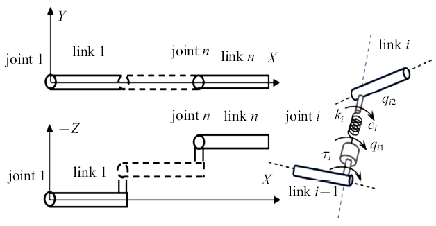
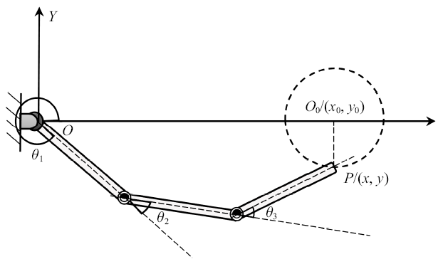
柔性铰柔性杆机器人是由$n$个铰和$n$根杆件组成的空间链式多体系统, 如图1所示.图1
 新窗口打开|下载原图ZIP|生成PPT
图1柔性铰柔性杆机器人
Fig. 1The robot with flexible joints and flexible links
柔性杆模型基于Euler-Bernoulli梁, 变形处于线弹性阶段. 模型中考虑了杆件拉压、弯曲变形和扭转变形. 柔性铰模型基于Spong的柔性关节简化模型, 将柔性铰看成线性扭转弹簧, 并考虑铰阻尼的存在. $\tau_{i}$为铰$i$的驱动力矩, $k_{i}$为铰$i$扭转刚度系数, $c_{i}$为铰$i$阻尼系数, $q_{i1}$为铰$i$驱动装置的角位移, $q_{i2}$为铰$i$传到杆件$i$的角位移. $q_{i2}-q_{i1}$为铰柔性引起的扭转变形.
1.2 柔性机器人的运动学描述
在建模过程中, 引入齐次坐标和齐次变换矩阵来描述杆件的位置和姿态. 为清楚表示各坐标系之间的转换关系, 在$i$杆的近端和远端各建立两个正交坐标系: 坐标系($X_{b}Y_{b}Z_{b})_{i}$固定在$i$杆的近端, 沿$X_{b}$沿杆件$i$未变形时的中性轴; 坐标系($X_{d}Y_{d}Z_{d})_{i}$固定在$i$杆的远端, 在杆$i$未变形时, ($X_{d}Y_{d}Z_{d})_{i}$看作是($X_{b}Y_{b}Z_{b})_{i}$沿杆件$i$的轴线方向平移杆件$i$的长度$L_{i}$而成; 坐标系($H_{x}H_{y}H_{z})_{i}$固定在$i$杆件的远端, $z$轴沿着关节的转轴; 坐标系($H_{x}H_{y}H_{z})_{i}'$固定在杆件$i$的近端, 铰$i$未动时, ($H_{x}H_{y}H_{z})_{i}'$与($H_{x}H_{y}H_{z})_{i-1}$重合. 可见, 坐标系($X_{d}Y_{d}Z_{d})_{i}$与坐标系($H_{x}H_{y}H_{z})_{i}$之间的4$\times$4齐次变换矩阵$dH_{i}$是一个常数阵, 坐标系($H_{x}H_{y}H_{z})_{i}$与($X_{b}Y_{b}Z_{b})_{i}$之间的变换矩阵$Hb_{i}$也是一个常数阵, ($H_{x}H_{y}H_{z})_{i}'$与($H_{x}H_{y}H_{z})_{i-1}$之间的变换矩阵$HH_{i}^{i-1}$只是铰$i$铰变量$q_{i2}$的函数.定义铰$i$的变换矩阵为$A_{i}$, 即从坐标系 $(X_{d}$ $Y_{d}$ $Z_{d})_{i-1}$到坐标系$(X_{b}$ $Y_{b}$ $Z_{b})_{i}$的变换矩阵, 则
定义$E_{i}$是杆件$i$的变形变换矩阵, 即从坐标系($X_{b}Y_{b}Z_{b})_{i}$到杆件$i$变形后的坐标系($X_{d}Y_{d}Z_{d})_{i}$的变换矩阵. 由于杆件$i$的变形是基于小变形假设, 故$E_{i}$可近似表达为
式中
其中, $x_{ij}$, $y_{ij}$, $z_{ij}$分别是杆件$i$的第$j$变形线位移模态在坐标系($X_{b}Y_{b}Z_{b})_{i}$的三轴上的分量; $\theta _{xij}$, $\theta_{yij}$, $\theta_{zij}$分别是杆件$i$的第$j$变形角位移模态在坐标系($X_{b}Y_{b}Z_{b})_{i}$的三轴上的分量; $\delta_{ij}$是杆件$i$的第$j$个模态坐标; $N_{i}$是杆件$i$的模态数.
令$W_{i}$是基座坐标系($X_{b}Y_{b}Z_{b})_{0}$到($X_{b}Y_{b}Z_{b})_{i}$之间的齐次变换矩阵, 则
其中${\mathord{\buildrel{\lower3pt\hbox{$\scriptscriptstyle\frown$}}\over {W}}}_{i-1}$是基座坐标系($X_{b}Y_{b}Z_{b})_{0}$到杆件$i-1$的远端坐标系($X_{b}Y_{b}Z_{b})_{i-1}$的齐次变换矩阵.
采用假设模态法描述杆件的变形, 考虑由杆件横向变形引起的纵向耦合变形. 杆$i$上某点$P$($\eta $, 0, 0)变形后在连体坐标系中的齐次坐标$^{i}h_{i}$为
式中, $x_{ijk}$($\eta $)是采用非线性应变场产生的高阶耦合项, 与传统零次动力学模型不同, 考虑了该项的高次刚柔耦合动力学
模型能够捕捉到大范围运动与变形的相互影响, 所得结果更加精确. $x_{ijk}(\eta $)可表示为
该点在基座坐标系中的齐次坐标$h_{i}$可以表示为
将$h_{i}$对时间求导, 可以得到该点的速度为
1.3 系统的动能和势能
系统的动能包括杆的动能和铰的动能. 杆$i$的动能可表示为上式中, $L_{i}$为杆$i$长度, $\mu _{i}$为柔性杆单位长度质量, Tr($\cdot$)表示对括号中的矩阵求迹, $J_{xi}$为杆$i$绕$x_{i}$轴单位长度转动惯量, $\theta_{xi}$为杆$i$绕$x_{i}$轴扭转角. 式(10)中, 右边的第一项为杆件大范围运动、纵向拉压变形运动和横向弯曲变形运动引起的动能, 第二项为杆件扭转变形运动引起的动能. 其中, $\theta _{xi}$可表示为
柔性铰$i$的动能分为平动动能和转动动能. 对于平动动能,把铰$i$看作杆$i$靠近铰$i$端的集中质量计入杆的动能. 而柔性铰$i$的转动动能可表示为
式中, $J_{ri}$为铰$i$转动惯量, $\varphi_{i}$是转子的角位移, 经过齿轮变速后输出角位移$q_{i1}$到柔性铰上, 因此$q_{i1}=\varphi _{i}/n_{i}$, 其中$n_{i}$为齿轮传动比. 于是式(12)可表示为
综上, 系统的总动能为
系统的势能包括柔性杆和柔性铰的弹性变形势能以及它们的重力势能. 柔性杆$i$的弹性势能包括拉压变形势能、弯曲变形势能、扭转变形势能
其中, $E_{i}$是杆$i$的杨氏模量, $G_{i}$是杆$i$的剪切模量, $A_{xi}$是杆$i$的横截面积, $I_{xi}$是杆$i$横截面关于中性轴的极面积惯性矩, $I_{yi}$和$I_{zi}$是杆$i$横截面关于$y_{i}$和$z_{i}$轴的面积惯性矩, $\theta_{yi}$和$\theta_{zi}$为杆$i$绕$y_{i}$和$z_{i}$轴转角. $\theta_{xi}$如式(11)所示, $\theta_{yi}$, $\theta_{zi}$可表示为
$x_{i}$为杆件$i$的拉压变形, 可表示为
柔性铰$i$的弹性势能为
系统的弹性势能为
系统的重力势能为
其中, $g$为重力加速度阵, $r_{i}$为杆$i$质心位置矩阵, 其具体形式见参考文献[23]. 于是系统的总势能为
1.4 系统的动力学方程
取广义坐标将系统的动能(14)和势能(22)代入到第二类拉格朗日方程
得到系统的动力学方程组为
以上得到的方程为考虑铰阻尼的柔性杆柔性铰机器人刚柔耦合动力学方程, 其中的相关变量可以参看文献[6-7, 17, 23]. 双下划线部分为考虑铰阻尼时产生项, 该项会使系统的动力学响应衰减. 以上方程最终可整理成如下矩阵形式
其中, $J$为广义质量矩阵, $R$为广义力矩阵.
2 柔性铰柔性杆机器人的动力学仿真
2.1 验证算例
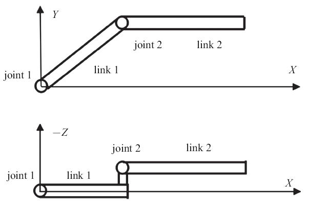
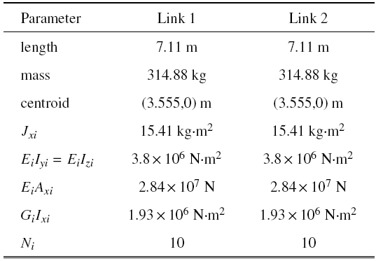
使用文献[17]中由两个柔性杆和两个柔性铰组成的空间机器人模型, 如图2所示. 杆件1与杆件2之间的间距为$d=0.475$ m, 由于此间距的存在, 杆件1会发生扭转变形. 考虑铰质量产生的项为$n_{i}^{2}J_{ri}=5$ kg$\cdot $m$^{2}$. 杆件1初始角度为$\pi$/4, 系统在重力作用下运动. 取与文献[17]中相同的模型参数, 如表1所示.图2
 新窗口打开|下载原图ZIP|生成PPT
图2柔性二连杆机器人
Fig. 2The flexible robot with two joints and two links
Table 1
表 1
表 1柔性机器人杆件参数
Table 1
 |
新窗口打开|下载CSV
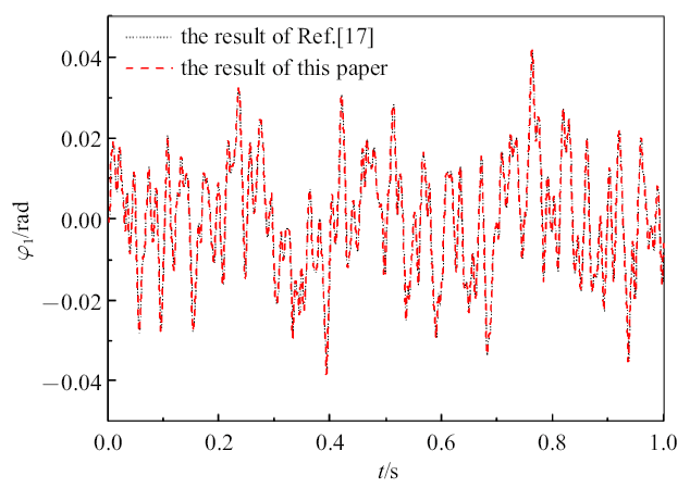
将本文不考虑铰阻尼时(即双下划线项为零时)杆1的扭转变形与参考文献[17]中杆1的扭转变形进行对比, 如图3所示. 本文结果与文献[17]中结果一致, 验证了本文建模和程序的正确性.
图3
 新窗口打开|下载原图ZIP|生成PPT
图3结果对比
Fig. 3The comparison of results from the present model with those from Ref.[17]
2.2 柔性单铰单杆机器人动力学仿真
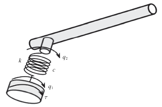
柔性单铰单杆机器人模型如图4所示. 柔性杆长度$L=1.8$ m, 杆密度$\rho =2.766\times 10^{3}$ kg/m$^{3}$, 杆的横截面积$S=2.5\times 10^{-4}$ m$^{2}$, 杆截面惯性矩$I=1.3021\times10^{-10}$ m$^{4}$, 杆的弹性模量$E=6.9\times10^{10}$ N/m$^{2}$, 驱动转子齿轮的传动比$n_{i}=10$, 驱动转子的转动惯量$J_{r}=7.0\times 10^{-3}$ kg$\cdot $m$^{2}$. $q_{1}$为驱动转子传到铰上的角位移, $q_{2}$为铰传到杆件的角位移. 驱动力矩为$\tau $, 铰的刚度系数为$k$, 铰的阻尼系数为$c$. 由于铰柔性的存在, 铰存在扭转变形, 驱动转子上的驱动转角$q_{1}$并不等于杆件的实际转角$q_{2}$.图4
 新窗口打开|下载原图ZIP|生成PPT
图4柔性单铰单杆模型
Fig. 4The flexible robot with single joint and single link
输入的驱动力矩为
该驱动力矩的大小为一个周期的正弦函数, 故对于刚性铰刚性杆机器人, 在所给力矩作用下, 机器人从静止开始转动, 先加速后减速最终回到静止状态.
2.2.1 铰刚度对机器人动力学响应的影响
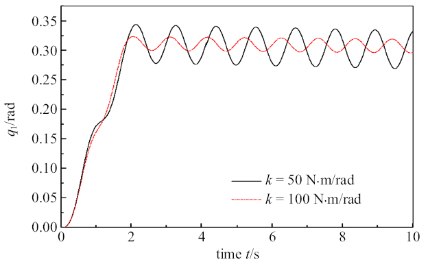
为了探究铰刚度对柔性机器人动力学响应的影响, 对不考虑铰阻尼时不同铰刚度的情况进行仿真分析. 图5为不同铰刚度时铰的驱动转角. 图6为不同铰刚度时铰的实际转角. 图7为不同铰刚度时驱动转角与实际转角的差值.
图5
 新窗口打开|下载原图ZIP|生成PPT
图5铰的驱动转角
Fig. 5The driving angular displacements of the joint
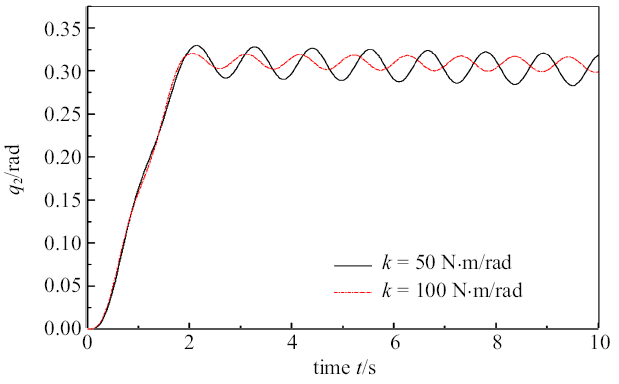
图6
 新窗口打开|下载原图ZIP|生成PPT
图6铰的实际转角
Fig. 6The actual angular displacements of the joint
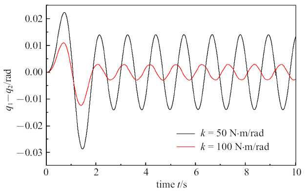
图7
 新窗口打开|下载原图ZIP|生成PPT
图7驱动转角与实际转角的差
Fig. 7The difference between the driving angles and the actuating angles
在刚性铰情况下驱动转角$q_{1}$和实际转角$q_{2}$相等, 而在柔性铰情况下, 铰存在扭转变形, 驱动转角$q_{1}$和实际转角$q_{2}$不相等. 铰的刚度越大, 驱动转角$q_{1}$和实际转角$q_{2}$越接近. 随着铰刚度的增大, 驱动转角$q_{1}$和实际转角$q_{2}$的振动幅值变小, 振动频率变大. 故可调节铰的刚度系数的大小来实现柔性机器人的减震和控制.
2.2.2 铰阻尼对机器人动力学响应的影响
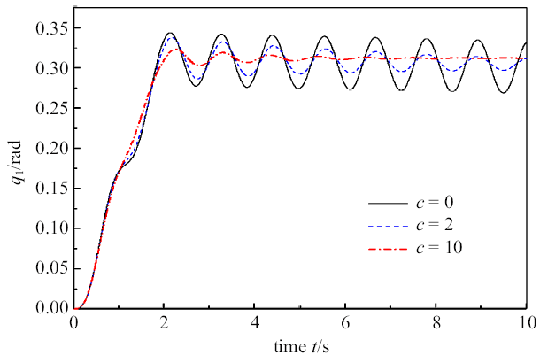
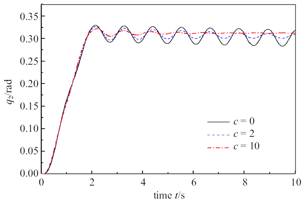
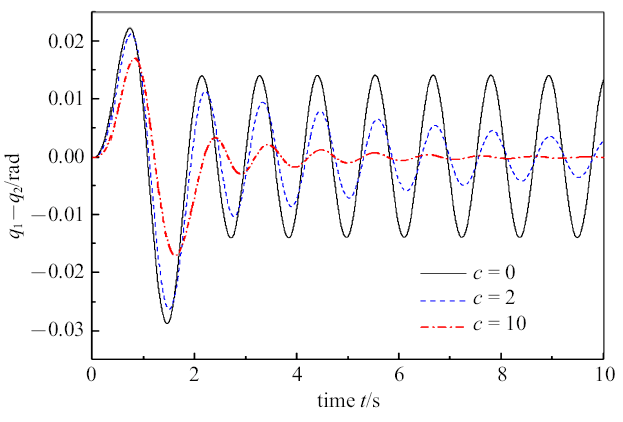
为了探究铰阻尼对柔性机器人动力学响应的影响, 对相同铰刚度时不同铰阻尼的系统进行仿真分析. 将柔性铰的刚度取$k=50$ N$\cdot$m/rad. 图8为不同铰阻尼时铰的驱动转角. 图9为不同铰阻尼时铰的实际转角. 图10为不同铰阻尼时铰驱动转角与实际转角的差值.
图8
 新窗口打开|下载原图ZIP|生成PPT
图8铰的驱动转角
Fig. 8The driving angles of joint
图9
 新窗口打开|下载原图ZIP|生成PPT
图9铰的实际转角
Fig. 9The actuating angles of joint
图10
 新窗口打开|下载原图ZIP|生成PPT
图10驱动转角与实际转角的差
Fig. 10The difference between the driving angles and the actuating angles
不考虑铰阻尼时, 驱动转角$q_{1}$、实际转角$q_{2}$、会一直振动下去. 铰阻尼的存在, 会使驱动转角$q_{1}$、实际转角$q_{2}$的振动衰减. 且铰阻尼越大, 驱动转角$q_{1}$、实际转角$q_{2}$衰减越快. 故可调节铰阻尼系数的大小来实现柔性机器人的减振和控制.
3 铰柔性对机器人动力学控制的影响
机器人控制属于动力学逆问题, 即已知系统轨迹对应的位移、速度和加速度求解所需关节力或力矩. 在系统动力学方程中, 广义力可分为与控制有关的广义力和包含了重力、离心力等与控制无关的其他部分的广义力. 其中, 控制广义力作为控制变量, 对机器人运动实施跟踪控制. 这里, 控制广义力可以是作动器驱动力、阻尼力、弹簧力或者它们的线性组合. 为求解此控制变量, 首先需要建立系统无控制时的动力学方程, 通过在此动力学方程中添加机器人末端运动所需要的约束方程, 建立机器人系统带有约束方程的动力学微分代数方程. 其次, 按照相关控制要求, 释放一定数量的控制变量, 在此情况下求解微分代数形式的动力学方程, 获得满足运动需求的系统运动参数. 最后由求解得到的运动参数, 通过逆动力学求解得到所需要的控制变量, 以此控制变量为前馈输入, 再通过反馈控制方法(如PID方法)施加到系统上, 便可使系统完成指定的运动.以图11所示机械臂为例, 系统由3根刚性杆和3个转动铰组成. 系统参数为: $L_{i}=7.11$ m, $\rho _{i}S_{i}=44.287$ kg/m, $n_{i}^{2}J_{ri}=5$ kg$\cdot$m$^{2}$, $i=1$, 2, 3. 使三连杆末端执行器做如下圆周运动
式中$r=5$ m, $\omega =0.314$ rad/s, $\beta =-\pi /2$.
图11
 新窗口打开|下载原图ZIP|生成PPT
图11三连杆机械臂
Fig. 11Three-link robot
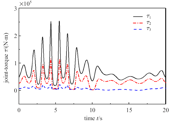
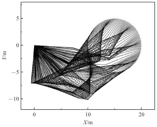
在刚性铰情况下, 经过逆动力学求解得到机械臂3个铰上所需施加的驱动力矩如图12所示, 此刚性铰系统的运动位形如图13所示.
图12
 新窗口打开|下载原图ZIP|生成PPT
图12关节力矩
Fig. 12The joint-torques
图13
 新窗口打开|下载原图ZIP|生成PPT
图13三连杆机械臂的位形
Fig. 13The configuration of the 3-link system
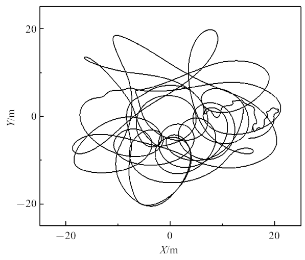
将图12中刚性铰情况下求得的驱动力矩施加到柔性铰系统时, 得到柔性铰系统末端执行器的运动轨迹如图14所示. 此时, 柔性铰的刚度取$k_1=k_2=k_3=1330$ N$\cdot$m/rad.
图14
 新窗口打开|下载原图ZIP|生成PPT
图14末端执行器运动轨迹
Fig. 14The movement of end-effector
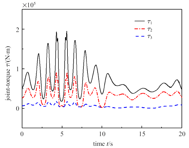
由图14可见, 杆末端轨迹为不规则运动, 与指定圆周运动差别巨大. 因此在机器人动力学控制时, 铰的柔性不可忽略, 需要对柔性铰系统进行研究. 对柔性铰系统进行动力学逆问题求解得到的3个铰上所需施加的驱动力矩如图15所示.
图15
 新窗口打开|下载原图ZIP|生成PPT
图15关节力矩
Fig. 15The joint-torques
由图12和图15可见, 完成相同指定运动, 柔性铰情况下所需的驱动力矩小于刚性铰情况下所需的驱动力矩. 将图15力矩施加在柔性铰系统上, 得到柔性铰的三连杆机械臂运动的位形与图13一样.
4 结论
本文对考虑铰阻尼的柔性铰柔性杆机器人进行动力学建模, 推导出包含杆扭转变形、铰质量效应的刚柔耦合动力学方程. 并对两个具体模型进行仿真, 得到以下结论:(1) 随着柔性铰刚度的增大, 柔性铰柔性杆机器人的动力学响应幅值减小.
(2) 铰阻尼的存在, 会使系统的振动衰减. 随着柔性铰阻尼的增大, 柔性铰柔性杆机器人的动力学响应衰减变快.
(3) 在机器人动力学控制时, 铰的柔性不可忽略.
参考文献 原文顺序
文献年度倒序
文中引用次数倒序
被引期刊影响因子
[本文引用: 1]
[本文引用: 1]
DOIURL [本文引用: 1]
DOIURL [本文引用: 1]
DOIURL [本文引用: 1]
DOIURL [本文引用: 1]
DOIURL [本文引用: 1]

The three-dimensional dynamics of a flexible cantilever beam attached to a moving rigid body undergoing an arbitrarily three-dimensional large overall motion is investigated in this paper. A set of dynamic equations for two-dimensional transverse and one-dimensional longitudinal vibrations of the flexible beam is established by using Lagrange's governing equations of motions the coupling effects of dynamic method. In the construction of the the so called transverse deformation-induced longitudinal deformation is included, which leads to the consideration of the dynamic stiffening effects in the obtained dynamic equations. An example is given to show the validity of the method presented in this paper and also the significant effects of the dynamic stiffening terms on the deformation and the dynamic characteristic of the flexible beam, and the difference between the present modeling theory and the traditional vibration theory as well. The traditional vibration theory of flexible beam will produce large error when the flexible beam itself is at higher speed large overall motion. Once the speed reaches at a critical value, the traditional dynamic system will diverge. Whereas the present model has high precision and the dynamic system converges even if the flexible beam undergoes higher speed large overall motion.
DOIURL [本文引用: 1]
The three-dimensional dynamics of a flexible cantilever beam attached to a moving rigid body undergoing an arbitrarily three-dimensional large overall motion is investigated in this paper. A set of dynamic equations for two-dimensional transverse and one-dimensional longitudinal vibrations of the flexible beam is established by using Lagrange's governing equations of motions the coupling effects of dynamic method. In the construction of the the so called transverse deformation-induced longitudinal deformation is included, which leads to the consideration of the dynamic stiffening effects in the obtained dynamic equations. An example is given to show the validity of the method presented in this paper and also the significant effects of the dynamic stiffening terms on the deformation and the dynamic characteristic of the flexible beam, and the difference between the present modeling theory and the traditional vibration theory as well. The traditional vibration theory of flexible beam will produce large error when the flexible beam itself is at higher speed large overall motion. Once the speed reaches at a critical value, the traditional dynamic system will diverge. Whereas the present model has high precision and the dynamic system converges even if the flexible beam undergoes higher speed large overall motion.
[本文引用: 1]
[本文引用: 1]
DOIURL [本文引用: 1]
The dynamic modeling theory of a flexible beam which is rotating in a plane is further studied, and the highorder coupling dynamic model is investigated here. Both the transversal deformation and the longitudinal deformation of the flexible beam are considered. And the non-linear coupling deformation term, also known as the longitudinal shortening term caused by transversal deformation, is considered here. The high-order terms related to the non-linear coupling term are retained, which are ignored in the first-order approximation coupling modeling. Thus, we can get the rigid-flexible coupling dynamic equations of the system. The high-order coupling model can not only be used in small deformation case, but also in large deformation case. Then simulations, compared to the absolute nodal coordinate formulation and the first-order coupling model, are given to prove the validity of the high-order coupling model. And the results show that the high-order coupling model can make up for the deficiency of the first-order approximation coupling model in the large deformation situation.
[本文引用: 1]
[本文引用: 1]
[本文引用: 1]
[本文引用: 1]
[本文引用: 1]
[本文引用: 1]
DOIURL [本文引用: 1]
[本文引用: 1]
URL [本文引用: 1]
研究由N柔性杆和N柔性铰组成的空间机器人的动力学问题.把柔性铰简化成一个线性扭转弹簧,采用假设模态法表示杆件的弹性变形,运用Kane方法对全柔机器人进行动力学建模,推导出完整的系统动力学方程组.通过一个数值仿真算例,验证所做工作的可行性,并分析了柔性效应对机器人动力学响应的影响.
URL [本文引用: 1]
研究由N柔性杆和N柔性铰组成的空间机器人的动力学问题.把柔性铰简化成一个线性扭转弹簧,采用假设模态法表示杆件的弹性变形,运用Kane方法对全柔机器人进行动力学建模,推导出完整的系统动力学方程组.通过一个数值仿真算例,验证所做工作的可行性,并分析了柔性效应对机器人动力学响应的影响.
[硕士论文].
[本文引用: 7]
[Master Thesis].
[本文引用: 7]
[本文引用: 1]
[本文引用: 1]
DOIURL [本文引用: 1]
URL [本文引用: 1]
提出一种建立具有柔性关节的多柔杆机器人动力学方程的方法.首先给出了柔性关节及柔性臂杆的简化模型,然后利用Kane方法和假设模态法推导出完整的动力学方程并给出了递推公式.在此基础上利用一个算例研究了臂杆柔性与关节柔性对机器人动力学响应的影响.结果表明:所建立的动力学模型更接近于实际的柔性机器人系统;臂杆柔性与关节柔性都起着非常重要的作用,因此在柔性机器人的动力学建模与控制中应充分考虑它们的影响.
DOIURL [本文引用: 1]
[本文引用: 1]
[本文引用: 3]
[本文引用: 1]
[本文引用: 1]
DOIURL [本文引用: 1]
DOIURL [本文引用: 1]
DOIURL [本文引用: 1]
DOIURL [本文引用: 1]
DOIURL [本文引用: 1]
