 ,2), 郑骁挺, 刘晶, 魏瑞华北京化工大学机电工程学院,北京 100029
STUDY ON A DYNAMICS MODEL OF TAPPING MODE AFM AND ENERGY DISSIPATION MECHANISM$^{\bf 1)}$
Wei Zheng,2), Zheng Xiaoting, Liu Jing, Wei RuihuaCollege of Mechanical and Electrical Engineering,Beijing University of Chemical Technology, Beijing 100029,China通讯作者: 2)魏征,副教授,主要研究方向:微纳米力学. E-mail:weizheng@mail.buct.edu.cn
收稿日期:2020-04-2接受日期:2020-05-2网络出版日期:2020-07-18
| 基金资助: |
Received:2020-04-2Accepted:2020-05-2Online:2020-07-18
作者简介 About authors

摘要
轻敲模式下探针从远离到间歇性接触样品表面,是一个连续的能量耗散过程.针对该连续过程的能量耗散机理研究仅零星存在于各个文献之中,对于连续过程中各个阶段的能量耗散机理也没有一个系统的解释和实验验证.本文提出了新的位移激励下原子力显微镜探针-样品系统简化模型并得到了一维振子系统等效阻尼的计算方法,并通过该方法计算了探针在远离样品表面时的空气黏性阻尼和靠近样品时的空气压膜阻尼,分析了探针从远离样品到间歇性接触样品表面这一过程中的环境耗散机理变化,得到了原子力显微镜系统理论品质因数与探针工作位置的关系曲线;在此基础上设计了轻敲模式下的微悬臂梁扫频实验,得到了系统实验品质因数与探针工作位置的关系曲线,进而验证了理论模型的准确性. 本文通过对轻敲模式下AFM环境耗散机理进行理论分析和实验验证,希望可以对轻敲模式下AFM动力学特性及其阻尼作用机理有更近一步的认识,同时对微纳米机电系统 (MEMS/NEMS) 能量耗散机理的研究提供理论参考和实验方法.
关键词:
Abstract
In the tapping mode, the AFM probe experiences a continuous energy dissipation process when the probe gradually approaches the sample from a far distance to an intermittent contact. Researches on the energy dissipation mechanism of this continuous process still exists sporadically in various literatures, and there are few systematic explanations and experimental verifications for the energy dissipation mechanism of each stage in the continuous process. In this paper, a new simplified model of the AFM probe-sample system under displacement excitation is proposed, and a calculation method for the equivalent damping of the one-dimensional vibration system is obtained. By this method, the viscous damping of the air when the probe is far away from the sample surface and the air squeeze film damping when the probe is close to the sample are calculated. Finally, the change of the environmental dissipation mechanism in the process from the probe away from the sample to the intermittent contact with the sample surface is analyzed, and the relationship curve between the theoretical quality factors of the AFM system and the working positions of the probe is obtained. Based on this, the micro-cantilever frequency sweep experiments with different probes in tapping mode are carried out. The frequency sweep curves are obtained through the experiments, thus obtaining the experimental relationship curve between the quality factors of the system and the working positions of the probe. The accuracy of the theoretical model is verified from the experiments. Through theoretical analysis and experimental verification of the AFM environmental dissipation mechanism in tapping mode, a further understanding of the dynamics characteristics of tapping mode AFM and its damping mechanism will be provided by this study. At the same time, it provides theoretical reference and experimental methods for the research of the energy dissipation mechanism in Micro-nano electromechanical system (MEMS/NEMS).
Keywords:
PDF (9577KB)元数据多维度评价相关文章导出EndNote|Ris|Bibtex收藏本文
本文引用格式
魏征, 郑骁挺, 刘晶, 魏瑞华. 轻敲模式下 AFM 动力学模型及能量耗散机理研究$^{\bf 1)}$. 力学学报[J], 2020, 52(4): 1106-1119 DOI:10.6052/0459-1879-20-099
Wei Zheng, Zheng Xiaoting, Liu Jing, Wei Ruihua.
引言
微纳机械谐振器作为大多数微纳机电系统(micro/nano-electromechanical system, MEMS/NEMS) 的核心部件,是具有高灵敏度、高品质因数和高谐振频率等优越性能的微纳机械结构[1-2]. 原子力显微镜 (atomic force microscopy,AFM) 是微观领域中的基础应用工具,多用于研究样品表面的形貌特征和物理化学性质[3-5],其核心部件探针就是一种微纳机械谐振器,从力学上看就是一微悬臂梁.AFM有三种工作模式:非接触模式 (non-contact mode)、接触模式 (contact mode) 以及介于两者之间的轻敲模式 (tapping mode,TM),轻敲模式又被称为间歇接触模式 (intermittent-contact mode)[6-7]. 与不接触样品表面的非接触模式扫描以及可能损坏样品表面的接触模式扫描相比[8],轻敲模式可以在不损坏样品表面形貌以及物理性质的前提下得到精确度较高的样品表面形貌特征[9-10]. 因此,原子力显微镜的轻敲模式有着极其广泛的应用前景[11].
相对于振幅信号所绘制出的形貌图,通过激励信号与探针自由端响应信号的相位滞后而绘制出的相位图可以更准确地反映出样品表面的物理性质变化.振动理论和相关研究都表明,相位差与系统的能量耗散有关[12-13],因此探究 AFM 系统在扫描过程中的能量耗散机理变化,不仅可以更好地理解相位图的形成机理,指导操作者得到更合适的相位图;而且对于更大范畴的 MEMS/NEMS 能量耗散机理的进一步理解提供理论参考和实验方法.
在真空中,微悬臂梁系统的品质因数可以达到上万;而在实际应用中,微悬臂梁在空气中的品质因数为 100$\sim$1000,在液体中甚至会降到个位数[11,14].因此在日常的工作环境中,空气或液体的黏性阻尼是最主要的环境能量耗散机制之一.
早在 20 世纪 40 年代,Landau 等[15]就提出了低雷诺数流中的圆柱体绕流问题以及黏性流体中的高频振动问题. 在此基础上,Chen 等[16]将微悬臂梁看作是等宽度的圆柱体求解了系统的能量耗散并与实验进行了对比;Sader 等[17]建立了不同激励方式下微悬臂梁的能量耗散理论模型;Hosaka 等[18]则是利用将微悬臂梁看作是无数个微型小球集合的方式给出了自己的理论模型.而随着探针逐渐下移直至靠近样品表面,探针-样品间的作用机理同样也需要考虑到 AFM 系统的能量耗散机制中.Lévêque 等[19]探究了非接触模式下空气阻尼与探针-样品间距离的关系;魏征等[20-21]进一步研究了探针在接触样品并离开样品表面这一过程中,液桥以及压膜阻尼对 AFM 振动系统能量耗散的影响;除此之外,实际实验中所用探针,带针尖的探针其上部有涂层,如果考虑涂层的效应,其动力学行为会更加复杂[22].
轻敲模式下探针从远离样品到间歇性接触样品表面,是一个连续的能量耗散过程. 到目前为止,针对这一个连续过程的能量耗散机理研究还是零星存在于各个文献之中,对于连续过程中各个阶段的能量耗散机理也没有一个系统的解释和实验验证.因此,本文通过对这一过程进行理论分析和实验验证,以期对轻敲模式下 AFM 动力学特性及其阻尼作用机理有更近一步的认识;并为 MEMS/NEMS 减少能量耗散、提高微纳谐振器的品质因数提供重要的理论依据.
1 TM-AFM 探针-样品系统动力学模型
1.1 工作原理
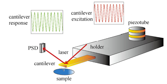
图 1 所示为轻敲式原子力显微镜核心部件-探针及其激励检测部分的简易示意图. AFM 探针包含 3 部分:基体部分、微梁部分和针尖部分.由于基体部分相对于微梁部分体积较大,因此微梁部分的右端可作为固定端,在探讨位移激励下的原子力显微镜微悬臂梁的动力学特性时,可以将针尖部分的质量忽略掉.图1
 新窗口打开|下载原图ZIP|生成PPT
图1轻敲式原子力显微镜核心部件-探针及其激励检测部分示意图
Fig.1Diagram of the core component of tapping atomic force microscopy-probe and its excitation detection part
在轻敲模式下,为使微悬臂梁得到较大的响应振幅,通过调制压电陶瓷驱动器,AFM 激励频率通常会接近或等于探针一阶固有频率[23];此时探针针尖会间歇性接触样品表面,监测所用的激光束打在探针尖端的背部,通过反射打到光电探测器 (PSD) 中. 当探针随着激励产生位移的时候,探测器上激光束光斑的位置也随之发生改变,通过相关参数的转换,系统就能够识别微悬臂梁的振动特性[24]. AFM 系统在工作时,由于黏性阻尼、热弹性阻尼、支撑损耗等能量耗散机理的存在,探针针尖的位移信号与激励信号会存在相位差;而当样品表面形貌或材料性质发生改变时,系统能量耗散也会随之改变进而导致相位差发生改变,这就是相位图的成像机理.
因此对于 AFM 系统而言,其品质因数 $Q$ 是最主要的工作性能参数之一. 通常情况下,品质因数 $Q$ 与系统的能量耗散有以下定义
其中,$W_0 $ 是 AFM 系统的总能量, $\Delta W$ 代表每一个振动周期 AFM 系统所损耗的能量. 而 AFM 系统在工作过程中的能量耗散机理从损耗途径来看,可以分为内禀耗散和外部耗散. 两种能量耗散途径中有着多种能量耗散机制,一般来说,需要分别求出每一种能量耗散机制所对应的品质因数,并最终得到系统总品质因数 $Q_{\rm total} $ 的表达式
其中,$Q_{\rm therm} $,$Q_{\rm viscous} $,$Q_{\rm support} $,$Q_{\rm other} $ 分别代表热弹性耗散、黏性耗散、支撑损耗以及其他耗散机制所对应的品质因数. 从式 (2) 可以看出,如何认识并确定微纳谐振系统的主要能量耗散机理,对获得高性能的 MEMS/NEMS 有着极其重要的意义.
除了本文主要讲述的黏性阻尼外,当 AFM 系统在室温或真空中工作时,热弹性阻尼也是主要的能量耗散机制之一,对于热弹性耗散机制,2000 年,Lifshitz 等[25]提出了一种较为精确的热弹性阻尼模型;而在探针振动时,探针固定端同样会激发出弹性波,并通过 AFM 系统基座向无穷远处耗散,这种能量耗散机制称之为支撑损耗.除此之外,探针的表界面损耗、声子相互作用等能量耗散机制同样会影响探针系统的品质因数.这些能量耗散机制同样不能忽视.
1.2 探针-样品系统的简化模型
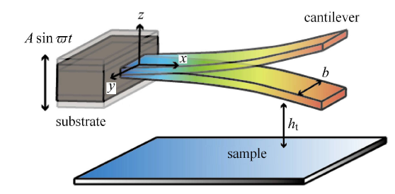
在轻敲模式中,压电陶瓷驱动器多放置于微悬臂梁的固定端,通过对探针固定端的基座施加位移激励,进而带动探针间歇式地敲击样品[26]. 现有文献中对 AFM 微悬臂梁受迫振动的处理主要集中在针尖样品间作用力的简化上,这对于解读样品的形貌和物理化学特性是主要的. 但如工作原理部分所述,样品所有信息全部由微悬臂梁的动态响应反映,从振动理论知,所有外部激励对微悬臂梁的响应都有贡献,因此除了大部分研究者所关心的针样间作用力外,位移激励和微悬臂梁与环境介质 (空气) 的相互作用也应该成为 AFM 微悬臂梁外部激励的一部分. 现有的欧拉-贝努利梁模型为了计算方便,是直接将外部位移激励忽略,把样品-针尖作用力看作是整个系统的外加载荷[27-29]. 当进一步简化成一维振子模型模型,更是将位移激励和梁与空气的相互作用一并忽略. 本文拟就这些因素对微悬臂梁的响应影响进行理论分析和实验研究.为研究方便,在探针没有接触样品前或离样品相当远时,针尖对于微悬臂梁的影响比较小,此时,可将图 1 的探针简化为图 2 所示的光梁模式.设悬臂梁上的位移为 $w(x,t)$;悬臂梁所受到的样品-针尖作用力为 $F_{\rm f} (w,\dot {w},h_{\rm t})$,则微悬臂梁的有阻尼振动微分方程为
其中,$EI$ 为微悬臂梁的截面弯曲刚度,$\rho$ 为微悬臂梁的材料密度,$b$ 和 $h$ 分别为微悬臂梁的宽度和厚度,$h_{\rm t}$ 为微悬臂梁平衡位置与样品间距离,$c$ 为单位长度上的系统阻尼系数.
图2
 新窗口打开|下载原图ZIP|生成PPT
图2探针-样品系统的多自由度简化模型
Fig.2Simplified multi-degree-of-freedom model for probe-sample system
如图 2 所示,悬臂梁相对于左端基座的相对位移为 $u(x,t)$;令左端基座的激励位 移为 $z(t)= w(x,t) - u(x,t) = A\sin \varpi t$. 式 (3) 可以写为
对于有针尖的微悬臂梁来说,当微悬臂梁靠近样品表面时,相对于针尖,其他部位与样品之间的作用力可以忽略不计. 因此,可以将该振动微分方程改写为
其中,$z_{\rm t} $ 为微悬臂梁自由端的位移.
首先需要考虑微悬臂梁的无阻尼自由振动问题,此时微悬臂梁的运动微分方程为
利用分离变量法,令 $u(x,t) = \varphi (x)q(t)$,可以得到微悬臂梁无阻尼自由振动各阶模态方程为
对于左端固定,右端自由的微悬臂梁,有边界条件
将边界条件代入 式 (7),可以得到 $i$ 阶模态下的振型函数
其中, $\beta _i = \dfrac{{\rm i}\pi }{l}$, $r_i = \dfrac{\sin \beta _i l - \sinh \beta _i l}{\cos \beta _i l + \cosh \beta _i l}$. 定义 $\omega _i = \beta _i^2 \sqrt {\dfrac{EI}{\rho bh}} $,为各阶固有频率.
同样,令 $u(x,t) = \varphi (x)q(t)$,将其代入 式 (9) 得位移激励下的有阻尼微悬臂梁各阶模态方程为
在小阻尼的情况下,振型函数同样可以用 式 (9) 表达. 将等式两边同时乘以 $\varphi _i (x)\text{d}x$,并沿整根梁的轴向积分,令 $\int_0^l {\rho bh\varphi _i (x) \text{d}x} = m_i $定义为 $i$ 阶面质量;$\int_0^l {\rho bh\varphi _i^2 (x) \text{d}x} = M_i $ 定义为 $i$ 阶主质量;将其代入可得
其中,$\xi _i = \dfrac{c_i }{2\rho bh\omega _i }$,为各阶的相对阻尼系数. 当探针在距离样品较远的位置上,可以忽略针尖-样品间作用力,因此有
在扫描样品时,探针的工作频率一般在其一阶固有频率附近,因此只需要考虑一阶模态.
对该振动方程进行求解,可以得到
其中,$s = \varpi /\omega _ 1 $ 为频率比, $\tan \phi = \dfrac{2\xi _i s}{(1 - s^2)s^2 - 4\xi _i^2 s^2}$;令 $B = \dfrac{m_ 1 A}{M_ 1 }\sqrt {\dfrac{s^{4} + (2\xi _ 1 s)^2}{(1 - s^{2})^2 + (2\xi _ 1 s)^2}}$,由此可以得到位移激励下的有阻尼微悬臂梁各阶稳态振动响应为
从式 (4) 中可以看出,轻敲模式下的微悬臂梁的振动响应是位移激励和系统各项阻尼的叠加. 位移激励下的微悬臂梁振动响 应为线性动力学行为,当位移激励 $A\sin \varpi t$ 施加在微悬臂梁的基座上时,可以看作是在整个悬臂梁上施加了一个 $q = \rho bh\varpi ^2A\sin \varpi t - c\varpi A\cos \varpi t$ 的均布载荷;而悬臂梁所受到的样品-针尖作用力会随着微悬臂梁的针尖与样品间距离而改变,为非线性动力学行为,可以看作是在微悬臂梁的自由端施加了一个与微悬臂梁位置、速度、位移有关的非线性作用力.
对TM-AFM的基体-探针-样品系统进行进一步简化时,如果直接将外部激励忽略,把样品-针尖作用力看作是整个系统的外加载荷,会得到一端固定,一端自由振动的弹簧-振子-阻尼器模型;但前文分析中可以看出,在微悬臂梁的根部施加位移激励,不能简单地忽略掉.
1.3 微悬臂梁的一维振子系统等效参数
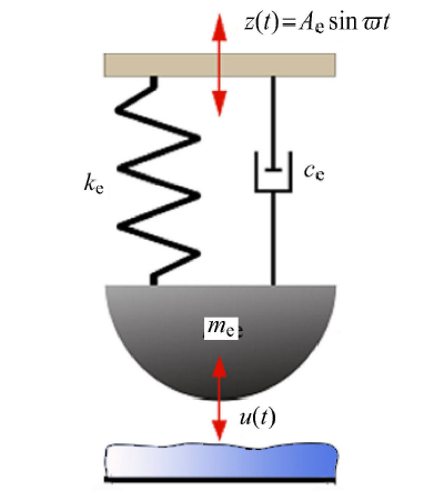
为了求解方便将 TM-AFM 的多自由度系统梁模型进一步简化为弹簧-振子-阻尼器模型时,考虑到位移激励,需要将其看作是支承运动下的弹簧-振子-阻尼器模型,如图 3 所示.图3
 新窗口打开|下载原图ZIP|生成PPT
图3支承运动下的弹簧-振子-阻尼器模型
Fig.3Spring-oscillator-damper model under support motion
由图 1 可知,光测探测器测量的是微悬臂梁自由端振动,因此等效刚度 $k_{\rm e} $ 可以表示为
而求解弹簧振子系统的等效质量,需要将梁的静挠度曲线作为微悬臂梁的近似振型,对于 AFM 系统来说,梁的自由端最大振幅 (10$\sim$100nm) 相对于梁的尺寸 (100$\sim$200$\mu $m) 可视为微小变形,因此用瑞利里兹法求弹簧振子系统的等效质量$m_{\rm e} $[6]
因此可以得到系统的固有频率
无论何种耗散机制,在 1.2 节已经把阻尼当成了黏性阻尼,现有文献一般都是把图 2 的固定端受位移激励的悬臂梁简化为类似于图 3 的一维振子模型,但实际的位移激励变成了作用于质量块上的激振力,此激振力大小没有具体讨论.另外图 3 的 $c_{\rm e} $ 与图 2 中黏性阻尼的对应关系也没有相关文献报道.
化简后的弹簧振子系统在一个周期内的能量耗散依然等于连续体梁系统,因此有
可求得图 3 等效阻尼 $c_{\rm e} $ 为
品质因数与等效阻尼之间的表达式如下
基座的位移激励为等效激励 $z(t) = A_{\rm e} \sin \varpi t$,$A_{\rm e}$ 为等效位移激励振幅;振子的位移响应同样为 $u(t)$,此时可以得到该系统的运动微分方程
在探究微悬臂梁的线性动力学行为时,可以先忽略掉悬臂梁所受到的样品-针尖作用力,只考虑位移激振对微悬臂梁的影响,即
对该方程进行求解,可以得到
振子的位移响应需要等同于悬臂梁末端的位移响应,因此联立式 (14) 与式 (23),当系统的频率比 $s$ 趋近于 1 时,可以得到等效的位移激励振幅为
其中,$\phi_1 $ 为相位滞后角,可以表示为
当系统的频率比 $s$ 趋近于 1 时,一维振子模型相位角 $\phi_1$ 可以等价于欧拉-贝努利梁模型的相位角 $\phi $.
2 TM-AFM探针-样品系统空气阻尼研究
在第 1 节中 提出了 TM-AFM 微悬臂梁动力学模型及进一步简化处理,所作结论还需要进一步实验验证,是一件有挑战性的工作,如 式 (3) 中的黏性阻尼,如何将阻尼力加载到梁上.在引言部分,我们已经谈到,TM-AFM 微悬臂梁的阻尼可分为内禀阻尼和外部阻尼两部分,其中内禀阻尼所占比重较小,外部阻尼中探针针尖与样品的接触分离阻尼相当于只作用在梁的自由端,虽然它对相位成像非常重要,但不在第1节考虑范围内,因此为简单起见,只考虑外部阻尼中的环境介质阻尼.2.1 气体介质的阻尼效应与尺度效应
真空环境下,AFM 系统可以不考虑黏性阻尼带来的能量耗散;但很多生物材料的检测和物理传感的工作要求限定了只能在气体或液体环境中才能进行. 因此在 AFM 系统的实际应用中,空气是最常见的流体环境,微尺度下的气体环境阻尼问题也是最受关注的能量耗散问题[30-31]. 一般情况下,从真空环境到常压,TM-AFM 系统的品质因数随真空度的改变而呈非线性变化;可以将这一变化分为 3 个阶段:本征区域、分子区域和黏性区域.(1) 本征区域气体阻尼特性:在本征区域,此时空气压强极低,AFM 系统的能量耗散主要为其他形式的能量耗散,因此可以将该工作环境近似为真空环境. 在本征区域阶段 AFM 系统的品质因数最大且较为稳定.
(2) 分子区域气体阻尼特性:在分子区域,随着压强的逐渐增大,气体分子开始随机撞击探针和样品表面,而气体内部分子之间的相互作用可以忽略. 此时气体阻尼开始影响AFM系统的品质因数大小,随着气体压强逐渐增大,AFM 系统的品质因数逐渐减小.
(3) 黏性区域气体阻尼特性:当气体压强增大到一定程度,该气体环境可以看作黏性流体,气体分子除了撞击探针和样品表面,自身内部也在不断地相互撞击逃逸;此时黏性阻尼在 AFM 系统的能量耗散中占据主导地位,随着气体压强逐渐增大,AFM 系统的品质因数进一步下降.
一般 TM-AFM 都是在实验室大气环境下工作,其微悬臂梁上的气体阻尼为黏性气体阻尼. 除此之外,还需要考虑气体介质的尺度效应. 通过气体分子的平均自由程 $\lambda$ 与流场中运动物体特征长度 $l_{\rm s}$ 的比值,可以判断流体是否适合连续流动,这一比值称为 Kundsen 数. Kundsen 数 $k_{\rm n} $ 表达式为[32]
对于气体分子的平均自由程,则可以表示为
其中,$k_{\rm B} $ 为玻尔兹曼常数,$T$ 为环境温度,$P_{\rm a}$ 为环境压力,$d_{\rm g} $ 为分子有效直径. 对于标准状态下空气而言,其气体分子的平均自由程 $\lambda $ 为 69nm.
微尺度下的物体在空气中运动时,Kundsen 数越大,气体越不满足连续性假设;而 Kundsen 数越小时,气体越满足气体的连续性假设.
由于尺度效应的存在,探针的工作过程中同样存在 3 个阶段:孤立阶段,压膜阶段以及失效阶段.
(1) 孤立阶段:微梁作为谐振器,在工作过程中存在临界压膜厚度 $h_{\rm cr} $, $h_{\rm cr} \propto b$,$b$ 为图 2 中梁的宽度. 当探针-样品间距离大于临界压膜厚度时,$k_{\rm n} \ll 1 $,可视为孤立阶段,需要把梁作为孤立物体来考虑空气阻尼.
(2) 压膜阶段:当探针-样品间距离小于临界压膜厚度时,需要考虑空气压膜效应来计算空气阻尼[8]. 从我们以前的实验中也可以看出[33],当探针靠近样品表面时,探针自由端的振幅从自由振动振幅的 100%依此衰减到 90%,85%,80% (即探针针尖越靠近样品表面),探针系统的品质因数也会随之减小. 因此在这个阶段除了考虑探针系统的环境阻尼能量耗散,还需要考虑探针-样品间的压膜阻尼效应所导致的能量耗散,该阶段可称作压膜阶段[34].
(3) 失效阶段:当微悬臂梁与样品间间距小于气体分子平均自由程时,$k_{\rm n} \gg 1 $,孤立阶段与压膜阶段作为连续介质假设的模型都将不再适用,此时扩散机制起主导[35].
作为实验的理论基础,本文主要对上述孤立阶段与压膜阶段的两种阻尼进行分析.
2.2 探针-样品系统的气体环境阻尼研究
从前一章节可以看出,AFM系统在标准大气压下工作时,气体环境阻尼为黏性阻尼. 在孤立阶段,对于黏性阻尼,在求解微悬臂梁单位长度上的单位空气阻尼力时,需要先确定一下流体类型. 对于流体而言,每一种类型的流体都取决于 3 个参数:运动黏度 $\nu$,运动速度 $\dot {u}$ 以及特征尺寸 $l_{\rm s} $. 3 个参数可以组成一个独立的无量纲数,即雷诺数其中,$\nu = \eta / \rho _a $ 为运动黏度,$\eta $ 为动力黏度,$\rho _{\rm a} $ 为流体密度.对于空气而言,动力黏度 $\eta =1.8\times 10^{ - 5}$kg/(s$\cdot$m), 运动 黏度 $\nu\!=\!1.5\times10^{- 5}$m$^2$/s,空气密度 $\rho _{\rm a}\!=\!1.293$kg/m$^{3}$.
对于常见 AFM 系统探针而言,其固有频率取 300kHz,特征长度 $l_{\rm s} $ 取探针宽度为 30$\mu$m,探针运动振幅取 10nm,可得雷诺数 $Re \ll 1 $,依此可以将空气看作小雷诺数流体;同样可以求得孤立阶段该运动的 Kundsen 数 $k_{\rm n} \gg 1 $,气体流动符合连续性假设.
此时将探针近似为无数个微小的球体,根据斯托克斯方程求解球体的绕流问题,可以得到梁振动时单位长度所受到的流体绕流阻尼系数为[18]
对于小雷诺数流体,$0.375Re$ 可以忽略.
因为探针高频运动的特殊性,还需要考虑探针振动时的穿透深度 $\alpha$. 对于黏性流体而言,当物体在流体中振动时,会出现与物体振动速度一致的横波,该横波在远离平板时会呈指数衰减的趋势,将振幅衰减为原来的 $1/ e$ 时的深度定义为穿透深度 $\alpha $. 穿透深度 $\alpha $ 的表达式为
因此,当探针在空气中振动时,探针周围有一层薄薄的有旋流,在距离物体表面较远的空气为有势流[16]. 在此基础上,如果位置在 $x$ 处的探针微元满足探针尺寸 $l$ 的量级远大于穿透深度 $\delta $,且探针的振幅远小于其尺寸,即
则该微元振动可以看作是高频振动,此时除了紧贴在探针表面的薄层,其他部分的空气都可以看作是理想流体.在常见的 AFM 系统中,探针长度 $l$ 的量级为 $10^{- 4}$m,系统角频率 $\omega$ 的量级为 $10^6$rad/s,探针振幅 $\varphi _1 (l)B$ 的量级为 $10^{ -8}$m,计算可知轻敲模式下样品-探针系统的运动满足式 (31),因此在考虑微悬臂梁在空气中所受到的流体阻尼系数时,需要同时考虑流体绕流现象所引起的绕流阻尼力以及微悬臂梁周围的有旋流所导致的高频振动阻尼力.根据斯托克斯方程可以得到梁高频振动时单位长度受到的流体黏度阻尼系数为[15]
将式 (29) 与式 (32) 代入式 (19),可得到简化后的一维弹簧振子系统其等效空气环境阻尼 $c_{\rm e1} $ 的表达式为
根据上式可以得到孤立阶段时,探针系统黏性耗散品质因数的表达式
由式 (32) 还可以得到临界压膜厚度 $h_{\rm cr} $ 的表达式[34]
式中,$\gamma $ 为表征流体运动一个无量纲数,其数量级为 $10^0 \sim 10^1$. 临界压膜厚度 $h_{\rm cr} $ 的取值为 $b / 2 \sim b$.
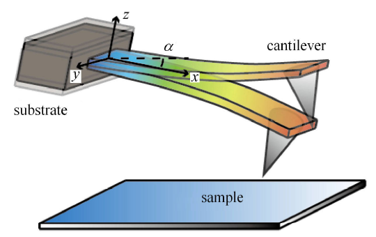
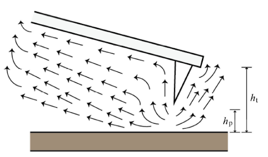
而当探针开始靠近样品表面时,需要开始考虑探针与样品间的挤压气膜所导致的能量耗散,如图 4 所示. 挤压数 $\tau $ 决定了空气膜的可压缩性,对于大挤压数,其空气薄膜力可以近似为弹性力;对于小挤压数,其空气薄膜力主要表示为阻尼力. 在 AFM 系统中,其挤压数可以表示为[27]
图4
 新窗口打开|下载原图ZIP|生成PPT
图4具有一定倾斜角度的带针尖探针敲击样品表面
Fig.4Probe with a certain tilt angle hits the sample surface
其中,$\mu _{\rm eff} $ 为有效空气黏性系数,其与动力黏度 $\eta$ 以及 Kundsen 数 $k_{\rm n} $ 的关系为[36]
可以求得,当探针针尖接触样品表面,即微悬臂梁距样品表面 15$\mu$m 时 (取探针针尖长度为 15$\mu$m),挤压数 $\tau \ll 1 $,此时探针所受到的挤压气膜力需要满足非线性雷诺方程[37]
其中,坐标轴的方向如图 4 所示,由于悬臂梁振幅较小,挠度忽略不计,$h_{\rm t} (x) = D + (l - x)\sin \alpha$ 代表气膜厚度;$D$ 为悬臂梁自由端到样品表面的距离,$\alpha $ 为倾 斜角;$P = P_{\rm a} + \Delta P$,$P$ 为微悬臂梁表面的压强分布,$\Delta P$ 为挤压气膜引起的偏压.
为了简化计算,忽略长度方向上的压力梯度,对 式 (37) 进行化简可以得到
再将上式沿宽度方向积分,并引入边界条件: $y = \pm b / 2$,$P = P_{\rm a} $;$y = {0}$,$\partial P/\partial y = 0$. 由此可以得到挤压气膜引起的偏压 $\Delta P$
对 式 (40) 再次积分,可以得到单位长度的挤压气膜力 $F_{\rm s}$
因此对于倾斜微悬臂梁,可以给出此时的压膜阻尼系数 $c_2 $ 的表达式为
将上式代入式 (18),可以得到
根据上式可以得到压膜阶段时,探针系统品质因数的表达式
但其实对于带针尖的探针而言, 如图 5 所示,由于针尖的存在,在探针-样品间距离 $h_{\rm t}$ 为 15$\sim$20$\mu$m 的时候,针尖-样品间距离 $h_{\rm p} $ 会远小于15$\mu$m. 此时针尖会大幅增加空气绕流对探针的影响,系统已经进入失效阶段,其特征尺寸 $l_{\rm s}$ 更应该取针尖-样品间距离而不是探针-样品间距离,可求得 Kundsen 数与挤压数会远大于之前的结果,因此实验的压膜阶段品质因数减小会比模型更加明显.
图5
 新窗口打开|下载原图ZIP|生成PPT
图5压膜阶段针尖对空气绕流的影响
Fig.5Effect of tip on air flow during lamination
3 实验
3.1 实验设计
为了验证前文 AFM 系统的简化模型以及环境耗散机理的正确性和准确性,分析在轻敲模式下探针从远离样品到间歇性接触样品表面这一过程中的能量耗散机理变换,需要得到探针从孤立阶段到压膜阶段在不同工作位置时的品质因数变化曲线.所用原子力显微镜为 BRUKER Dimension Icon.首先使用 Engage 功能让实验探针大致靠近样品表面,接着使用 tip offset 功能令实验探针远离样品表面,此时利用 auto tune 功能可以得到探针在远离样品表面的扫频曲线.
接着使用 tip offset 功能,令实验探针慢慢靠近样品表面,并记录每一次的进针量以及该进针量对应的扫频曲线.
由于 tip offset 的距离调节范围限定,无法在一次实验中同时得到孤立阶段与压膜阶段的扫频曲线. 探针自由端的振幅变化量对应于探针-样品距离,因此通过改变系统的 setpoint 值,可以设定探针自由端的振幅变化量,进而得到探针在远、中、近 3 个距离段的扫频曲线.
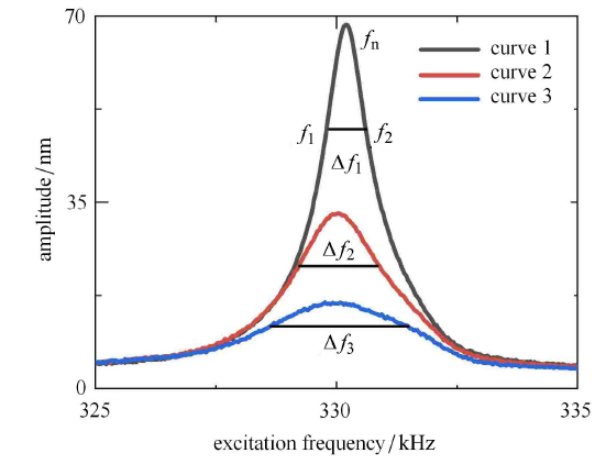
通过扫频曲线,便可以求出AFM系统的品质因数 $Q$. 所谓扫频曲线,其获取方式如图 1 所示,用一正弦电压激励压电管,在压电管产生频率相同的伸缩变形从而达到对探针根部的正弦位移激励,正弦电压的频率从低频向高频增高,依次通过探针的基频和几阶低倍频,这里我们最感兴趣的为探针的基频,因此扫频范围为第一阶频率附近即可,光敏传感给出探针自由端的相应振幅,TM-AFM 记录的幅频响应曲线如图 6 所示. 当系统响应幅值降到振幅的 $ 1 / \sqrt 2 $ 时的频率称为系统的半功率点,$f_1 $ 与 $f_{2} $ 都为半功率点,其差值 $\Delta f = |f_1 - f_2| $ 称为系统的带宽[38]. 对于小阻尼的振动系统,其品质因数 $Q$ 等于系统共振频率 $f_{\rm n} (f_{\rm n} =\omega _{\rm n} / 2 \pi )$ 与带宽 $\Delta f$ 的比值
图6
 新窗口打开|下载原图ZIP|生成PPT
图6通过三次距离改变所得扫频曲线及其带宽
Fig.6Sweep curve and its bandwidth obtained by changing the distance three times
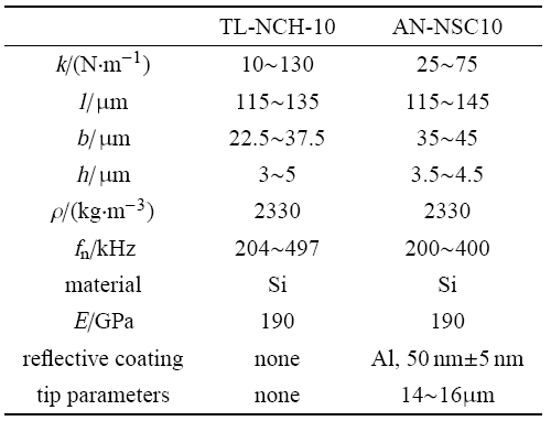
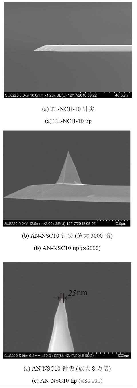
为了排除探针针尖对 AFM 系统能量耗散的影响,分别选取了探针型号为 TL-NCH-10 的无针尖探针以及探针选择型号为 AN-NSC10 的锥形针尖探针进行了扫频实验,两种型号探针尺寸参数如表 1 所示,其扫描电子显微镜 (scanning electron microscope,SEM) 图如图 7 所示 (扫频实验所用探针与电镜实验探针为同一型号的探针,但并不是同一根探针).
Table 1
表1
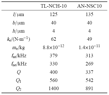
表1两种型号探针的尺寸参数
Table 1
 |
新窗口打开|下载CSV
图7
 新窗口打开|下载原图ZIP|生成PPT
图7两种实验探针 SEM 电镜图
Fig.7SEM images of two experimental probes
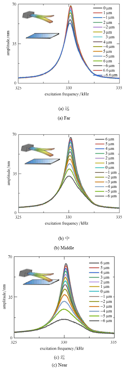
实验得到的无针尖探针远、中、近三距离段实验扫频曲线如图 8 所示;锥形针尖探针远、中、近三距离段实验扫频曲线如图 9 所示.由于压电管的行程限制,无法在一次实验中完成探针远离样品表面、靠近样品表面、接触样品表面这 3 个过程,因此通过 offset 选项调节探针基座位置来得到远中近 3 个位置,再通过系统的进针功能实现工作位置的微调.两种探针都分为远中近三段进行扫频实验,为得到实验数据完整,图 8(a)$\sim$ 图 8(c) 的探针行程区域有相当范围的重合,图 9(a)$\sim$ 图 9(c) 同样如此.另外图 8 和图 9 标注的探针位置为其相对位置,而非相对于某一静止点的位置表达.
图8
 新窗口打开|下载原图ZIP|生成PPT
图8无针尖探针实验扫频曲线
Fig.8Experimental frequency sweep curve of the tipless probe experiment
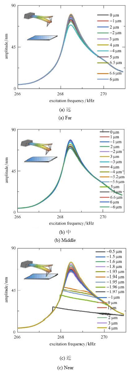
图9
 新窗口打开|下载原图ZIP|生成PPT
图9锥形针尖探针实验扫频曲线
Fig.9Experimental frequency sweep curve of conical tip probe
图 8 和图 9 有一个共同的现象,就是随着探针趋近于样品,整个扫频曲线的振幅都是下降的,特别在共振点,其下降非常明显,说明在趋近样品过程中,振动系统的阻尼在逐步增强.由于存在针尖,锥形针尖探针在接触样品时,会先出现敲击样品,这时 TM-AFM 形貌扫描的工作状态,随着探针进一步接近,由于较大黏附力的作用,探针针尖已经不能从样品脱附,就会出现如图 9(c) 部分曲线所示的"截断"现象,此时 无法判断探针-样品系统的品质因数.
3.2 实验结果分析
实验用探针经SEM显微镜和光学显微镜测量,无针尖探针长宽高分别为 125$\mu$m,40$\mu$m,4$\mu$m,锥形针尖探针长宽高分别为 135$\mu$m,40$\mu$m,4$\mu$m. 依据式 (15)$\sim$ 式 (17) 可以将探针简化为如图 3 所示的一维弹簧振子模型并得到简化后的等效刚度 $k_{\rm e} $、等效质量 $m_{\rm e}$,以及其理论一阶固有频率 $f_{\rm nt}$ 如表 2 所示.根据图 8 和图 9 扫频实验结果,可以得到无针尖探针和锥形针尖探针实验一阶固有频率 $f_{\rm ne}$ 分别为 330kHz 和 269kHz.Table 2
表2
表2两种探针的参数以及实验与理论品质因数
Table 2
 |
新窗口打开|下载CSV
再根据图 8 与图 9 的扫频实验结果,可以分别得到无针尖探针和锥形针尖探针在远离样品表面时的品质因数 $Q$;根据式 (34) 可以求出两种探针的理论黏性耗散品质因数 $Q_1 $;同时根据式 (2) 中还可以求出除黏性耗散之外其他所有能量耗散品质因数 $Q_{2} =(Q^{ - 1} - Q_1^{ - 1} )^{ - 1}$. 3 种品质因数的对比同样如表 2 所示.
从无针尖探针在远离样品表面时的黏性耗散品质因数为 560,除黏性耗散外的其他所有能量耗散品质因数 1400 以及实验得到的总品质因数 400 相对比可以看出,黏性耗散为轻敲模式下 AFM 系统最主要的能量耗散机制. 对于锥形针尖探针而言,由于只考虑探针主体部分而没有考虑锥形针尖,因此理论得到的黏性耗散品质因数 542 会偏大,其机理类似于图 5 的示意性分析,但与除黏性耗散外的其他所有能量耗散品质因数 891 (实际会偏大) 相对比依然可以得出黏性耗散为轻敲模式下 AFM 系统最主要的能量耗散机制这一结论.
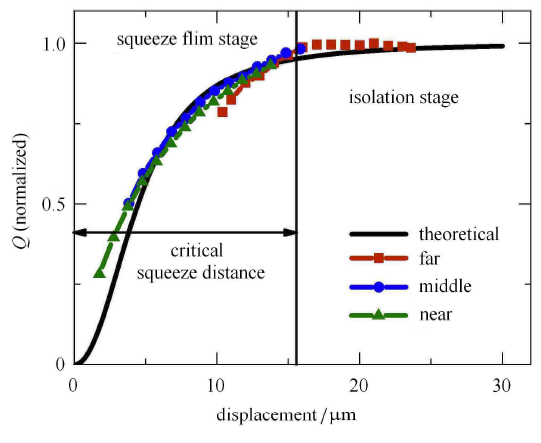
为了进一步探究压膜阶段探针品质因数与探针工作位置的关系,验证理论模型的正确性,可以通过图 8 得到实验无针尖探针品质因数与工作位置的实验关系曲线. 探针倾斜角一般为 10$^\circ$$\sim$15$^\circ$[39],本文取 15$^\circ$,再根据式 (44) 可以求得无针尖探针黏性耗散品质因数与工作位置的理论关系曲线. 如图 10 所示,为了更好地对比实验与理论分别得到的无针尖探针品质因数与工作位置关系曲线,忽略除黏性阻尼外其他阻尼的影响,可以对实验与理论得到的无针尖探针黏性耗散品质因数与工作位置关系曲线都进行归一化处理.
图10
 新窗口打开|下载原图ZIP|生成PPT
图10理论与实验无针尖探针品质因数与工作位置的关系曲线对比 (归一化)
Fig.10Theoretical and experimental comparison of the relationship between the quality factor of tipless probes and the working position (normalized)
图 10 中,从实验曲线和理论曲线可以非常清晰地看出无针尖探针在逐渐靠近样品表面时品质因数两个阶段的变化.
在孤立阶段,如图 8(a) 所示,当探针距样品表面较远时,可以将探针看作一个孤立的物体;此时从图 10 中的理论曲线和实验曲线都可以看出尽管探针-样品间距离逐渐减小,探针的品质因数并没有出现明显的变化.这与图 4 我们之前的实验结果吻合.
而随着探针逐渐靠近样品,当探针-样品间距离达到临界压膜距离 $h_{\rm cr}$ 时,探针开始感受到压膜力,阻尼开始增大.图 10 的临界压膜距离为 16$\mu$m,式 (35) 所得到的理论预测为 20$\sim$40$\mu$m,实验值比较小的原因是由于实验中探针的倾斜. 理论曲线与实验曲线的高度拟合说明探针与样品间确实会存在压膜阻尼.如图 8(b) 和图 8(c) 所示,探针进入压膜阶段,此时如图 10 中理论曲线和实验曲线所示,随着探针-样品间距离逐渐减小,探针的品质因数也逐渐减小;探针越接近样品表面,压膜阻尼对探针品质因数的影响越大.
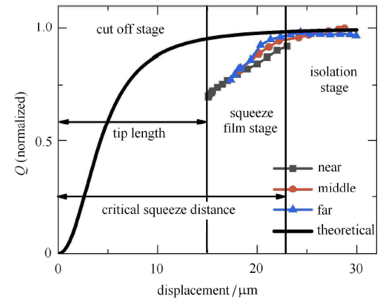
如图 11 所示,同样根据图 9 扫频实验结果,可以求出锥形针尖探针品质因数与工作位置的关系曲线;根据式 (44) 求出锥形针尖探针黏性耗散品质因数与工作位置关系的理论曲线并与实验曲线一起进行归一化处理并对比.
图11
 新窗口打开|下载原图ZIP|生成PPT
图11理论与实验锥形针尖探针品质因数与工作位置的关系曲线对比 (归一化)
Fig.11Theoretical and experimental comparison of the relationship between the quality factor of conical tip probes and the working position (normalized)
从图 11 中,同样可以很清楚的看出锥形针尖探针在逐渐靠近样品表面时其品质因数在孤立阶段与压膜阶段的变化.
在孤立阶段,如图 9(a) 与图 9(b) 的部分实验结果所示,探针距样品表面较远,此时从图 11 中可以看出,探针的品质因数并不会随着探针-样品间距离的减小而出现明显的变化;而随着探针-样品间距离达到临界压膜距离 $h_{\rm cr} $,探针进入压膜阶段,探针的品质因数会随着探针-样品间距离的减小而减小. 式 (35) 忽略了针尖对系统压膜阻尼的影响,因此这里的临界压膜距离比无针尖探针的距离大. 之后再紧接着如图 9(c) 所示,由于较大黏附力的作用,探针针尖已经不能从样品脱附,就会出现如图 11 截断阶段所示,无法判断探针的品质因数.
从图 11 还可以看出,实验的压膜阶段品质因数减小比理论曲线更加明显,其主要原因在于式 (44) 所表示的理论模型忽略了探针针尖的存在. 从图 5 中可以看出,当探针靠近样品时,针尖会极大地增加空气绕流对探针振动的影响,进而降低探针的品质因数;除此之外,此时如图 7(c) 所示,探针针尖由于存在曲率半径,可以将其看作探针针尖上存在一个可以和样品表面产生压膜效应的小球,因此在这一阶段压膜阻尼对探针品质因数的影响也会比理论模型更为明显. 大多数文献[40,41] 都认为在压膜阶段针尖的影响可以忽略,但从实验中可以看出针尖不能忽略,该阶段的针尖-样品间压膜阻尼作用可以成为以后的重点研究方向.
对比图 8(a)$\sim$ 图 8(c) 与图 9(a)$\sim$ 图 9(c)的扫频曲线以及图 10 与图 11 的品质因数-工作位置关系曲线还可以看出:对于无针尖探针来说,当悬臂梁距离样品很近时,品质因数可以下降到 25%,图 8(c) 的相对应的幅频曲线依旧很光滑;相反,对于锥形针尖探针来说,从图 11 中的实验曲线看出,悬臂梁品质因数只下降到 75% 左右图 9(c) 相对应的幅频曲线便出现了"截断"现象.其主要原因在于假定某个振动周期系统的总输入能量是恒定的,依据式 (1),这表明锥形针尖所受到的压膜阻尼不足以耗散所有能量以阻止针尖到达样品表面,故而会出现截断现象,也就是针尖会碰到样品.相反,无针尖探针靠近样品表面时,能量耗散极其严重,这或将导致悬臂梁振幅太小而无法到达样品表面.
4 结论
(1) 大部分针对原子力显微镜探针的动力学分析,都将施加在微悬臂梁基座上的位移激励忽略掉,只考虑样品-针尖作用力,将外部作用力看作是施加在微悬臂梁自由端从而进行求解.从分析中可以看出,这是两种不同的振动方程,当忽略位移激励时,样品-针尖作用力看作是系统的外加激励,此时相当于是在微悬臂梁的自由端施加了一个简谐力;而当位移激励施加在微悬臂梁的基座上时,可以看作是在整个悬臂梁上施加了一个均布力,两种不同的简化方式会导致不同的动力学响应.
(2) 通过将探针系统简化为一维弹簧阻尼振子系统,可以较方便地分析探针系统的动力学特性等问题. 本文提出了微悬臂梁简化为一维弹簧阻尼振子系统的简化准则,即等效阻尼、等效位移激励的表达式.
(3) 探针在远离样品表面时,其主要能量耗散机理为空气黏性阻尼;当探针靠近样品时,其主要能量耗散机制为探针与样品间的压膜阻尼. 本文提出了一个计算微悬臂梁等效黏性阻尼的新方法,通过该方法计算了考虑空气黏性阻尼和空气压膜阻尼的等效黏性阻尼,并与实验结果进行了对比,结果表明模型是合理的.
(4) 本文只探究了 AFM 系统孤立阶段与压膜阶段时的环境介质阻尼作用机理,但由于探针针尖的存在,压膜阻尼发生很大的变化,其所导致的能量耗散将是我们下一步研究的重点.
参考文献 原文顺序
文献年度倒序
文中引用次数倒序
被引期刊影响因子
DOIURL [本文引用: 1]
[本文引用: 1]
[本文引用: 1]
[本文引用: 1]
DOIURLPMID [本文引用: 1]
DOIURL [本文引用: 2]
DOIURL [本文引用: 1]
//
[本文引用: 2]
DOIURL [本文引用: 1]
[本文引用: 1]
DOIURLPMID [本文引用: 2]

Higher harmonics have been widely used to characterize nanomechanical properties of the sample surface in tapping mode atomic force microscopy. They are usually analyzed by the Fourier transform method which provides time-averaged amplitude and phase information. In this paper, we apply the analytic wavelet transform to analyze higher harmonics. The intuitive descriptions of higher harmonics are obtained by the time-frequency analysis of the tip motion signal. The temporal evolutions of the higher harmonics are analyzed. The higher harmonics extracted by the analytic wavelet transform are closely related to the wavelet parameters. Different time and frequency features of higher harmonics can be analyzed through adjusting the wavelet parameters. Moreover, the root-mean-square amplitude and the peak amplitude obtained by the analytic wavelet transform can provide better characterization of sample properties than the amplitude obtained by the Fourier transform method.
[本文引用: 1]
[本文引用: 1]
DOIURL [本文引用: 1]
[本文引用: 2]
[本文引用: 2]
DOIURL [本文引用: 2]
DOIURL [本文引用: 1]
DOIURL [本文引用: 2]
DOIURL [本文引用: 1]
URL [本文引用: 1]
URL [本文引用: 1]
[本文引用: 1]
[本文引用: 1]
DOIURL [本文引用: 1]
[本文引用: 1]
DOIURLPMID [本文引用: 1]
The nonlinear vibration behavior of a Tapping mode atomic force microscopy (TM-AFM) microcantilever under acoustic excitation force has been modeled and investigated. In dynamic AFM, the tip-surface interactions are strongly nonlinear, rapidly changing and hysteretic. First, the governing differential equation of motion and boundary conditions for dynamic analysis are obtained using the modified couple stress theory. Afterwards, closed-form expressions for nonlinear frequency and effective nonlinear damping ratio are derived utilizing perturbation method. The effect of tip connection position on the vibration behavior of the microcantilever are also analyzed. The results show that nonlinear frequency is size dependent. According to the results, an increase in the equilibrium separation between the tip and the sample surface reduces the overall effect of van der Waals forces on the nonlinear frequency, but its effect on the effective nonlinear damping ratio is negligible. The results also indicate that both the change in the distance between tip and cantilever free end and the reduction of tip radius have significant effects on the accuracy and sensitivity of the TM-AFM in the measurement of surface forces. The hysteretic behavior has been observed in the near resonance frequency response due to softening and hardening of the forced vibration response.
DOIURL [本文引用: 1]
[本文引用: 1]
[本文引用: 1]
DOIURL [本文引用: 2]
DOIURL
Micro electromechanical system (MEMS) is an electromechanical device of microscale, in which micro-plate is the most typical structure. Its acoustical and mechanical properties influence the design of MEMS significantly. The vibroacoustic performance of simply supported micro-plate subjected to simultaneous stimulation of sound pressure and gas film (squeeze film) damping force is analyzed theoretically, the latter induced by the vibration of a micro-plate having similar size. By applying the Cosserat theory and the Hamilton principle, micro scale effects due to characteristic length and Knudsen number are taken into account. The governing equations are subsequently solved using the method of multiple Fourier transform to quantify sound transmission loss (STL) across the micro-plate. In the frequency domain, the effects of squeeze film under different circumstances (e.g., different characteristic lengths and Knudsen numbers, different vibration frequencies and amplitudes) on STL are investigated systematically. This work demonstrates the great influence of micro-scale effects, as well as vibration, on STL. Decreasing the vibration amplitude and increasing the distance between micro-plates lead to better performance of sound transmission. Results presented in this study provide useful theoretical guidance to the practical design of micro-plates in MEMS.
DOIURL [本文引用: 1]
[本文引用: 1]
[本文引用: 1]
[本文引用: 1]
[本文引用: 1]
[本文引用: 1]
[本文引用: 1]
[本文引用: 1]
[本文引用: 1]
DOIURL [本文引用: 1]
DOIURL [本文引用: 1]
DOIURL [本文引用: 1]
DOIURL [本文引用: 1]
[本文引用: 1]
DOIURLPMID [本文引用: 1]
In Atomic force microscope (AFM) examination of a vibrating microcantilever, the nonlinear tip-sample interaction would greatly influence the dynamics of the cantilever. In this paper, the nonlinear dynamics and chaos of a tip-sample dynamic system being run in the tapping mode (TM) were investigated by considering the effects of hydrodynamic loading and squeeze film damping. The microcantilever was modeled as a spring-mass-damping system and the interaction between the tip and the sample was described by the Lennard-Jones (LJ) potential. The fundamental frequency and quality factor were calculated from the transient oscillations of the microcantilever vibrating in air. Numerical simulations were carried out to study the coupled nonlinear dynamic system using the bifurcation diagram, Poincare maps, largest Lyapunov exponent, phase portraits and time histories. Results indicated the occurrence of periodic and chaotic motions and provided a comprehensive understanding of the hydrodynamic loading of microcantilevers. It was demonstrated that the coupled dynamic system will experience complex nonlinear oscillation as the system parameters change and the effect of squeeze film damping is not negligible on the micro-scale.
DOIURL [本文引用: 1]
