RESEARCH ON THE MAGNETO-MECHANICAL EFFECT IN ACTIVE AND PASSIVE MAGNETOSTRICTIVE VIBRATION ISOLATOR 1)
Niu Muqing*,??, Yang Bintang*, Yang Yikun*, Meng Guang*, Chen Liqun*,2)收稿日期:2018-08-2接受日期:2018-11-6网络出版日期:2019-03-18
| 基金资助: |
Received:2018-08-2Accepted:2018-11-6Online:2019-03-18
作者简介 About authors
2)陈立群,教授,主要研究方向:非线性动力学与振动控制.E-mail:chenliqun@hit.edu.cn

摘要
磁致伸缩材料和柔顺位移放大机构组成的主动驱动装置具有精度高、驱动力大等特点.将其与被动隔振装置并联,形成主被动隔振装置,可以弥补纯被动隔振在低频和微幅扰动工况下的不足.本文针对这类磁致伸缩主被动隔振装置进行磁机耦合效应研究.基于Jiles-Atherton模型,分析了磁致伸缩材料所受应力对有效磁场、磁化强度、磁致伸缩系数和材料杨氏模量的影响,表征了材料磁机耦合效应.在此基础上,建立了主被动隔振装置的动力学模型,分析了主动驱动装置与被动隔振装置间的耦合作用.在耦合作用影响下,若被动隔振装置刚度不同,即使输入磁场相同,驱动器产生的驱动位移和驱动力也不相同.磁致伸缩材料的变刚度效应使隔振装置整体等效刚度不再为定值,从而影响被动隔振效果.本文提出了通过柔顺机构参数设计减小前述两种耦合影响的方法.数值仿真结果表明,磁致伸缩主被动隔振装置在低于、接近和高于谐振频率三类扰动下,都能达到比被动隔振更好的振动抑制效果.此外,仿真结果验证了考虑磁机耦合效应的数值模型具有更高精度.
关键词:
Abstract
The actuation system, which is composed of magnetostrictive actuator and compliant displacement amplifier, has the advantages of high precision and large actuation force. It is connected in parallel with passive vibration isolator. The resulting active and passive vibration isolator can make up for the deficiencies of passive isolator on low-frequency and micro-amplitude conditions. In this paper, a nonlinear magnetostrictive actuation model is proposed based on Jiles-Atherton model. Magneto-mechanical effect is comprehensively characterized by being decomposed into stress related effects on effective field, magnetization, magnetostriction and Young's modulus. A dynamic model of the isolator is established considering the coupling effects between active isolator and passive isolator. With the coupling effect, the performance of actuation system is related to passive isolator parameters. With higher passive isolator stiffness, the actuation displacement decreases and the required actuation force increases. The coupling effect also leads to the change of equivalent stiffness of the isolator due to the ?E effect of magnetostrictive material. The influence of coupling effects can be weakened by parameter design of compliant amplifier. The performances of the active and passive vibration isolator are validated by numerical simulation. Three kinds of vibration frequencies are used, which are below, around and beyond natural frequency of the isolator, respectively. Compared to passive vibration isolator, better vibration isolation performances are acquired by adding active vibration isolator on all three conditions. And the calculation results show that the proposed model considering magneto-mechanical effect can reach a higher accuracy.
Keywords:
PDF (2730KB)元数据多维度评价相关文章导出EndNote|Ris|Bibtex收藏本文
本文引用格式
牛牧青, 杨斌堂, 杨诣坤, 孟光, 陈立群. 磁致伸缩主被动隔振装置中的磁机耦合效应研究 1). 力学学报[J], 2019, 51(2): 324-332 DOI:10.6052/0459-1879-18-254
Niu Muqing, Yang Bintang, Yang Yikun, Meng Guang, Chen Liqun.
引 言
在航空航天[1]和精密制造领域,精密设备易受到外界振动干扰而导致性能下降,甚至完全失效.隔振装置可以使振动在传递至被隔对象的过程中有效衰减,保障设备正常运行.传统被动隔振装置具有结构简单、可靠性高的优点,但低频隔振性能差,在结构参数变化时无法主动调节;且对于微幅振动,部分摩擦作用无法正常发挥,容易导致阻尼元件失 效[2].近年来,非线性被动隔振装置[3]的研究一定程度上弥补了带宽和时变时滞[4]方面的不足,但仍无法满足日益严苛的隔振要求.主动隔振装置通过在受控系统中引入次级振源而抵消振动,可以作为被动装置的补充有效解决前述问题.磁致伸缩驱动器是一种基于铁磁材料磁致伸缩效应[5]的应变式驱动器,具有分辨率高、驱动力大、频带宽、响应快等特点[6-7],被广泛应用于直线电机[8]、液压器件[9-10]、进给装置[11-12]、隔振装置[13-14]等.基于磁致伸缩驱动的主动隔振装置适用于高精度、大负载工况.日本Nakamura公司研制了两代六自由度主动隔振平台,采用8个磁致伸缩和气动混合驱动器,有效载荷达到1.5 t[15-16]. 美国IAI(Intelligent Automation Inc.)公司针对航天应用研制了Stewart构型的磁致伸缩主动隔振平台,主动行程可达$\pm$127μm,隔振率在30 dB左右[17].
在磁致伸缩隔振装置动力学建模方面,Braghin等[18]采用线性模型描述磁致伸缩驱动,将主动隔振装置等效为一个恒定刚度的弹性元件和一个与输入磁场成线性关系的主动力,该模型仅在特定工况条件下有效.周浩淼等[19]采用非线性物理模型描述磁致伸缩驱动,隔振装置产生的主动力同时受输入磁场和应力影响.张婷等[20]采用非线性唯象模型描述磁致伸缩驱动,将隔振装置视为"黑箱",采用Bouc-Wen方程描述,利用逆模型进行控制.上述模型都将磁致伸缩驱动器独立的等效为一个主动力或恒定刚度的弹性元件,忽略了其与被动隔振装置间的耦合作用.事实上,磁致伸缩驱动器的驱动位移与驱动力与其所受结构反力密切相关,且磁致伸缩材料杨氏模量随磁化状态变化,其内刚度变化且与所受应力相关[21-22].
驱动器与被动隔振装置间的耦合作用源于磁致伸缩材料本身的磁机耦合效应,机理复杂且表现形式多样.Sablik等[23]应用热力学理论推导了应力对材料内部磁畴间相互作用力的影响.Jiles[24]研究了磁机耦合作用下应力变化对材料磁化强度的影响,提出了"接近理论(law of approach)"进行量化描述.Jiles[24]还指出应力对磁致伸缩系数的影响,并根据实验结果修正了磁致伸缩系数模型.郑晓静等[25]利用双曲正切函数建立了一种材料本构关系模型,既描述了应力对磁致伸缩系数的影响,还表征了材料杨氏模量随磁化强度和应力变化的特征,即变刚度效应($\Delta E$ effect).上述研究阐释了磁机耦合效应的某一个或几个部分,量化了特定工况下展现出的特定磁机耦合现象,但尚不全面.磁致伸缩材料在隔振应用中应力变化快且变化范围大,几乎所有磁机耦合现象都很显著,全面表征磁机耦合效应对于装置动力学建模至关重要.
本文采用拆分建模的方法,全面表征了磁致伸缩材料的磁机耦合效应,在此基础上建立了主被动隔振装置的动力学模型,分析了主动驱动装置和被动隔振装置间的耦合作用,通过仿真验证了装置的隔振效果,以期为这类装置的设计提供参考依据.
1 磁致伸缩主被动隔振装置建模
1.1 隔振装置基本结构
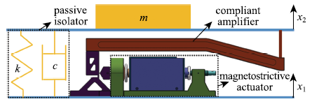
单自由度磁致伸缩主被动隔振装置结构如图1所示,装置分为两层,下平面为扰动面,位移$x_{1}$,上平面为负载面,位移$x_{2}$,负载质量M,两层之间为并联的隔振装置,其中被动隔振装置包括刚度为k的 k弹性元件和阻尼为c的阻尼元件,主动驱动装置由磁致伸缩驱动器和柔顺位移放大机构组成.图1
 新窗口打开|下载原图ZIP|生成PPT
图1磁致伸缩隔振装置基本结构
Fig.1Structure of magnetostrictive isolator
磁致伸缩驱动器沿水平方向输出,以其材料伸长方向为正方向(图中水平向左),产生的驱动位移记为$x_{\rm a}$,驱动力记为$F_{\rm a}$.柔顺机构起到放大驱动位移和改变驱动力方向的作用,其结构、材料和放大机理如图2所示,输入端与驱动器固连,输出端作用于上平面的主动力记为$F$.柔顺机构具体尺寸和建模方法详见文献[26],本文直接使用建模结果.
图2
 新窗口打开|下载原图ZIP|生成PPT
图2柔顺位移放大机构结构图
Fig.2Structure of compliant amplifier
隔振装置所受扰动从下平面施加,当驱动器无外加磁场时,装置处于纯被动隔振状态,其隔振效果不仅取决于被动隔振装置,还取决于磁致伸缩材料的等效刚度以及柔顺机构的刚度,即使在无外加磁场状态下,磁致伸缩材料的等效刚度也会因其所受应力变化而改变.对驱动器施加外加磁场后,主动驱动装置对上平面提供了额外的驱动力,装置处于主被动隔振状态.
1.2 磁致伸缩驱动建模
本文基于Jiles-Atherton(JA)模型[27]对磁致伸缩驱动进行非线性物理建模,JA模型是以Weiss分子场理论和微磁学理论为基础而建立的,其基本表达式为[28]式中,He为有效磁场强度,H为输入磁场强度,M为磁化强度,$M_{\rm an}$为无滞回磁化强度,$\lambda$为磁致伸缩系数,$\varepsilon$为应变,$\sigma$为应力,$\sigma$0为预应力.此外还有7个材料本质属性参数,$\alpha$为分子场系数,a表征有效磁场密度,Ms为饱和磁化强度,r为可逆畴壁运动比例,w代表打破钉扎效应所需要的平均能量,$\lambda$s为饱和磁致伸缩系数,Em为材料平均杨氏模量.
模型中磁化强度包含可逆磁化强度$M_{\rm rev}$和不可逆磁化强度$M_{\rm irr}$两部分,其中不可逆磁化强度与磁化强度、饱和磁化强度之间的关系可表示为
将上式对有效磁场求导并代入式(3)可得
将磁机耦合效应分为4个部分,分别建模并引入上述模型.第一部分是应力与有效磁场耦合,应力会影响磁畴间相互作用力,进而影响有效磁场,因此式(1)可修正为[20]
式中,mu0为真空磁导率.
第二部分是应力与磁化强度耦合,应力变化会造成磁畴转动,进而改变磁化强度,由"接近理论"推导可得[21]
式中,xi是以单位体积能量为单位的比例系数,E为材料在每一时刻的等效杨氏模量.
在磁机耦合效应作用下,磁化强度变化率同时取决于有效磁场变化率和应力变化率
将式(6)、式(7)、式(9)代入式(10)可得
第三、四部分分别是应力与磁致伸缩系数耦合以及变刚度效应,基于磁致伸缩材料本构关系模型,式(4)和式(5)可分别修正为包含应力的函数[22]
式中,Es为饱和杨氏模量,$\sigma_{s}$为饱和应力,$\sigma$0为预应力.将式(12)代入式(8))可得到有效磁场表达式为
此外,磁致伸缩材料杨氏模量并非定值,而是与材料磁化强度和所受应力相关,其应力-应变关系并非线性.针对这类变刚度材料,一般采用应力对应变的导数作为材料在该状态下的等效杨氏模量,由式(12)和式(13)求导可得杨氏模量倒数表达式
1.3 隔振装置建模
磁致伸缩材料的长度和截面积分别记为$L_{T}$和$A_{T}$,则其驱动位移为若驱动器不含碟簧,则驱动力与磁致伸缩材料受力互为反力
柔顺位移放大机构的建模方法可参见文献[26],在小变形前提下,柔顺机构线性度较好,其建模结果可表示为
式中第一个矩阵取决于柔顺机构的材料、结构和尺寸,$-F$表示上平面作用于柔顺机构输出端的反力.结合被动隔振装置,系统响应可表示为
综上所述,图1所示隔振装置模型可表示为
该模型为隐式微分方程形式,可采用龙格库塔法逐步求解.
2 主、被动隔振装置间耦合作用分析
2.1 被动隔振参数对驱动性能的影响
在相同的工况条件下,改变被动隔振装置中的刚度或阻尼会导致磁致伸缩材料所受应力变化,进而改变驱动器输出.考虑空载无阻尼无扰动工况,仅保留被动隔振装置中的弹性元件,则
将式(21)代入式(18)化简可得
上式表征了驱动器产生单位位移所需要提供的驱动力,其值与被动隔振刚度k成正相关.将式(12)、式(13)、式(22)联立化简可得应力求解方程
上式为超越方程,可采用牛顿法求取磁化强度M对应的应力$\sigma$数值解,再代入磁致伸缩驱动模型即可求得驱动器输出.
被动隔振刚度对驱动器输出的影响难以建立解析解表达式,通过算例进行数值解分析.驱动器和柔顺机构主动隔振装置磁致伸缩材料相关参数为:$\alpha$=2.4×10⁻³,Ms=960 kA/m,a=7.3 kA/m,w=15 kA/m, $\xi$=770 kPa,r=0.85,$\sigma$s=240 MPa,Es= 110 GPa,$\lambda$s=1.04×10⁻³,$\sigma$0=-6.5 MPa,LT= 100 mm,$A_{\rm T}$=314 mm2,耦合放大器相关参数p11, p12,p21, p22分别为126, 2.55, 2.55, 59.2 N/μm.
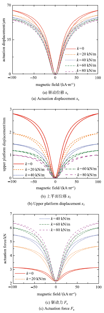
算例采用幅值100 kA/m,频率1 Hz的正弦输入磁场,该磁场强度可以保证磁致伸缩材料达到饱和. 负载质量M、阻尼c、下平面位移$x_{1}$都为0,不同k值下主动隔振装置的输出如图3所示.
图3
 新窗口打开|下载原图ZIP|生成PPT
图3不同k值下驱动器输出
Fig.3Actuator output with different k value
在不同k值下,磁致伸缩材料在相同输入磁场下所受应力不同,受磁机耦合效应影响,产生的磁致伸缩应变和弹性应变都不同.
k值越大,驱动位移越小,如图3(a)所示.不同k值下柔顺机构的位移放大倍数也不同,具体关系参见文献[26],k值越大,放大倍数越小,因此上平面位移的差异相对于驱动位移更大,k=0时的位移约为k=80 kN/m时的2.74倍,如图3(b)所示.此外,k值越大,驱动器所需要提供的驱动力也越大,如图3(c)所示,驱动力要求过高容易导致磁致伸缩材料尺寸过大、柔顺机构内应力过大等问题.在高频工况下,除弹簧刚度外,阻尼和负载质量也会通过磁机耦合影响磁致伸缩驱动器输出.
若k取值范围为[0,$\infty )$,则式(22)的取值变化范围为[$p_{11}-p_{12}p_{21}$/$p_{22}$,$p_{11})$,其上下限取决于柔顺机构设计.这一分析提供了一种减小被动隔振刚度对磁致伸缩驱动性能影响的方法,即通过合理的柔顺机构设计,使$p_{12}p_{21}$/$p_{22}$的值远小于$p_{11}$,则$F_{\rm a}$/$x_{\rm a} \approx p_{11}$,减小了k值对磁致伸缩材料所受应力的影响.
记图2中箭头指示的一处厚度尺寸为$t_{\rm b}$,改变该尺寸得到式(22)在不同k值下的取值如表1所示,其中k=0时$F_{\rm a}$/$x_{\rm a}$值即为$p_{11}-p_{12}p_{21}$/$p_{22}$. 随着该厚度尺寸增大,$p_{11}-p_{12}p_{21}$/$p_{22}$与$p_{11}$的值越来越接近,不同k值下的$F_{\rm a}$/$x_{\rm a}$值趋于相等,即k值对磁致伸缩材料所受应力的影响越小. 需要说明的是,单一增大$t_{\rm b}$会造成机构放大倍数的急剧减小,柔顺机构的尺寸优化需要针对多个尺寸参数同时进行,本文仅以一个参数的变化验证该方法的有效性.
Table 1
表1
表1柔顺机构尺寸对Fa/xa值的影
Table 1
| tb/mm | Fa-Xa-1 /(N-m-1) (k=0) | Fa.Xa-1/(N.m-1) (k=80 kA/m) | P11 / (N-m-1) |
|---|---|---|---|
| 2.8 | 1.6X10⁷ | 7.9X10⁷ | 1.3X10⁸ |
| 5 | 6.3X10⁷ | 1.2X10⁸ | 2.0X10⁸ |
| 10 | 1.7X10⁸ | 2.0X10⁸ | 2.4X10⁸ |
| 15 | 2.0X10⁸ | 2.2X10⁸ | 2.6X10⁸ |
新窗口打开|下载CSV
2.2 变刚度效应对被动隔振性能的影响
主被动隔振装置一般要求主动隔振装置不工作时依然具备被动隔振功效,受偏置磁场、剩磁影响,磁致伸缩材料在不工作时的磁化强度可能不为0,其应力也会因系统反作用力而发生改变,受材料变刚度效应影响,其杨氏模量随磁化强度和应力变化,即非工作状态下的磁致伸缩驱动器可以等效为一个非线性弹性元件.磁致伸缩材料杨氏模量E可由式(15)计算,则其等效刚度$k_{\rm eq}$为
再结合式(18)可推导出此时主被动隔振系统等效刚度和固有频率为
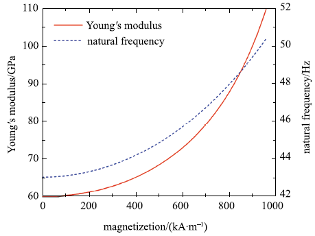
鉴于磁致伸缩材料杨氏模量表达式复杂,本文采用数值算例进行分析.磁致伸缩材料饱和应力$\sigma$s为100 MPa,其他材料参数和柔顺机构参数同表1,设负载质量10 kg,被动隔振装置刚度k=10 kN/m.为方便对比,将材料所受应力固定为预应力$-6.5$ MPa,仅改变磁化强度,材料杨氏模量和系统固有频率计算结果如图4所示.
图4
 新窗口打开|下载原图ZIP|生成PPT
图4变刚度效应及系统固有频率变化
Fig.4$\Delta E$ effect and natural frequency change
由图可知,当磁致伸缩材料磁化强度由0增大到饱和时,材料杨氏模量由60 GPa增大至110 GPa,相应的,隔振系统等效刚度增大,固有频率由43 Hz增大至50 Hz. 磁致伸缩材料的变刚度效应与材料成分相关,部分材料的杨氏模量变化范围更大,变化规律更加复杂,对隔振系统固有频率的影响也更大.再者,被动隔振过程中材料所受应力发生改变,进一步改变材料杨氏模量,使驱动器等效刚度变化规律更加复杂,若设计中不加以考虑,难以达到预期被动隔振效果.
由式(25)可知,合理的柔顺机构设计可以减小驱动器刚度变化对系统等效刚度的影响,一种方式是使$p_{11}$远大于$k_{\rm eq}$,这种方法只适用于等效刚度$k_{\rm eq}$较小的磁致伸缩材料,如薄膜状材料,否则$ p_{11}$过大的柔顺机构难以设计.第二种方法是使$p_{22}$远大于$p_{12}p_{21}$/($k_{\rm eq}+p_{11})$,此时系统等效刚度$k_{\rm sys} \approx k+p_{22}$,与$k_{\rm eq}$无关,规避了磁致伸缩材料变刚度效应对被动隔振性能的影响.
第二种方法的有效性通过计算不同$t_{\rm b}$对应的系统等效刚度$k_{\rm sys}$验证. 如表2所示,随着$t_{\rm b}$减小,不同$k_{\rm eq}$所对应的$k_{\rm sys}$差异越小,且其值越发接近$k+p_{22}$,表明磁致伸缩材料等效刚度对系统总体等效刚度的影响减小.
Table 2
表2
表2柔顺机构尺寸对系统等效刚度的影响
Table 2
| tb/mm | (k+P22)/ (N-m-1) | ksys/(N-m-1) (keq= 100 N/mm) | ksys/(N-m-1) (keq = 300 N/mm) |
|---|---|---|---|
| 2.8 | 6.9X10⁴ | 4.0X10⁴ | 5.4X10⁴ |
| 2 | 4.4X10⁴ | 3.1X10⁴ | 3.8X10⁴ |
| 1.5 | 2.8X10⁴ | 2.4X10⁴ | 2.7X10⁴ |
| 1 | 1.7X10⁴ | 1.6X10⁴ | 1.6X10⁴ |
新窗口打开|下载CSV
3 主被动隔振数值仿真
本节采用式(20)所示模型,对磁致伸缩主被动隔振装置进行数值仿真. 驱动器和柔顺机构参数如表1所示,被动隔振装置参数为:k=10 kN/m,c=100 N$\cdot$s/m,负载质量为10 kg.在下平面施加正弦位移振动干扰,计算上平面的位移响应作为隔振结果.本文计算了3种仿真结果,一是主动隔振装置不工作时的被动隔振效果.二是主动隔振装置工作,采用上平面位移响应作为反馈信号,采用PID方法对主动隔振器进行控制,从而得到主被动隔振效果,并分别计算了系统稳定后的峰峰值隔振率$\eta$$_{\rm pp}$和均方误差隔振率$\eta$ms
式中,$\|~\|_{2}$代表二范数.三是采用不考虑磁机耦合效应的模型,即磁致伸缩驱动器模型采用式(1)~式(5),采用与第二种仿真相同的输入信号,得到上平面位移响应,与考虑磁机耦合效应的模型作对比.
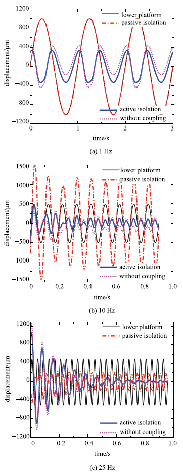
仿真采用低于、接近和高于谐振频率的三类扰动,分别对应1 Hz,10 Hz和25 Hz,为模拟航天应用中常见的低频大幅值扰动工况,1 Hz下扰动幅值为1 mm,而另两种工况扰动幅值为0.5 mm.
图5(a)所示为1 Hz扰动下的仿真结果,在这类低频扰动下,纯被动隔振完全失效,加入主动隔振后振动得到有效抑制,峰峰值隔振率和均方误差隔振率分别为66.2%和65.5%.图5(b)所示为10 Hz扰动下的仿真结果,该频率扰动激发了系统谐响应,被动隔振反而放大了振动,加入主动隔振后谐振现象得到显著抑制,稳定后的峰峰值隔振率和均方误差隔振率分别为80.5%和81.3%.图5(c)所示为25 Hz扰动下的仿真结果,该频率下被动隔振已能起到显著作用,加入主动隔振后,振幅突然增大,但快速衰减,稳定后达到了比被动隔振更好的隔振效果,峰峰值隔振率和均方误差隔振率分别为96.9%和97.7%.
图5
 新窗口打开|下载原图ZIP|生成PPT
图5隔振数值仿真结果
Fig.5Numerical results for vibration isolation
由仿真分析可知,图1所示主被动隔振系统在多种频率下均能达到比被动隔振更好的振动抑制效果,但也会出现图5(c)中振幅突然增大的情况.需要说明的是,对于磁致伸缩驱动器这类强非线性系统,PID控制并非最佳控制方法,本文旨在展现隔振系统特性和初步隔振效果,采用其他控制方法可以更好地避免系统不稳定并且提高稳定后的隔振效果,相关研究参见文献[29,30].
另一方面,从图5可以看出,在相同输入信号下,模型中是否考虑磁机耦合效应得到的计算结果不同.对比发现,不考虑磁机耦合效应的模型计算出的驱动位移偏大,主要原因是忽略了变刚度效应导致计算出的材料弹性形变偏小.因此,不考虑磁机耦合效应不仅会导致模型精度降低,还容易高估驱动器行程,造成基于该模型设计得到的隔振装置实际驱动性能无法达到预期.
图中加入主动隔振前后的振幅峰峰值差异近似反映了主动驱动位移的大小,驱动位移越大,磁致伸缩材料的磁化状态和应力状态改变也越大,是否考虑磁机耦合效应得到的计算结果差异也越明显. 因此,10 Hz仿真中主动驱动位移最大,两种计算结果差异最明显,而25 Hz仿真中主动驱动位移不到400μm,两种计算结果差异较小.
4 结 论
本文将磁致伸缩材料的磁机耦合效应拆分为应力-有效磁场、应力-磁化强度、应力-磁致伸缩系数和变刚度效应四个部分,实现了磁机耦合现象的全面表征.在此基础上建立了单自由度主被动隔振装置的动力学模型,并分析了主动驱动装置与被动隔振装置间的耦合作用.分析表明:若被动隔振装置刚度较大,磁致伸缩驱动器输出同等位移所需驱动力较大,驱动器在同等输入磁场下驱动位移较小;磁致伸缩材料等效刚度与其磁化状态和所受应力有关,这一变刚度效应使隔振装置整体等效刚度也不再是定值,从而影响装置被动隔振性能.本文提出了通过柔顺机构参数设计减小上述两种耦合影响的方法,通过数值计算验证了这一方法的有效性.在数值仿真中,通过施加低于、接近和高于谐振频率三类扰动,验证了磁致伸缩主被动隔振装置的隔振效果,也说明了不考虑磁机耦合效应的模型计算结果不精确,易高估驱动器行程,从而验证了在模型中考虑磁机耦合效应的必要性.参考文献 原文顺序
文献年度倒序
文中引用次数倒序
被引期刊影响因子
URL [本文引用: 1]

颗粒材料在高应力环境下会发生颗粒破碎现象,颗粒破碎不仅影响颗粒材料的力学特性,同时与大量工程问题密切相关.目前的相关研究主要集中在唯象地描述颗粒破碎的演化以及破碎对力学特性的影响层面,对颗粒破碎演化路径的物理机制研究较少.本文基于热力学框架,采用细观力学中细观-宏观的均匀化方法推导了颗粒体系弹性能和破碎能量耗散,并在最大能量耗散的假设下,在热力学框架内,建立了理想化的无摩擦球体颗粒等向压缩过程的弹性-破碎模型,阐述了颗粒材料破碎演化路径细观热力学机制.由于模型的推导不依赖任何唯象的经验公式,因此模型中包含的参数均有明确的物理意义.模型预测与前人试验结果对比表明,材料的初始级配对弹性压缩模量和破碎应力的影响并不相同:不同分形维数级配对应的弹性体变模量存在极大值,而破碎应力却随着分形维数的增大单调递增;颗粒破碎的演化符合最大能量耗散原理,且颗粒材料的压缩曲线可以分为弹性-破碎-拟弹性3个机制不同的阶段.
URL [本文引用: 1]
颗粒材料在高应力环境下会发生颗粒破碎现象,颗粒破碎不仅影响颗粒材料的力学特性,同时与大量工程问题密切相关.目前的相关研究主要集中在唯象地描述颗粒破碎的演化以及破碎对力学特性的影响层面,对颗粒破碎演化路径的物理机制研究较少.本文基于热力学框架,采用细观力学中细观-宏观的均匀化方法推导了颗粒体系弹性能和破碎能量耗散,并在最大能量耗散的假设下,在热力学框架内,建立了理想化的无摩擦球体颗粒等向压缩过程的弹性-破碎模型,阐述了颗粒材料破碎演化路径细观热力学机制.由于模型的推导不依赖任何唯象的经验公式,因此模型中包含的参数均有明确的物理意义.模型预测与前人试验结果对比表明,材料的初始级配对弹性压缩模量和破碎应力的影响并不相同:不同分形维数级配对应的弹性体变模量存在极大值,而破碎应力却随着分形维数的增大单调递增;颗粒破碎的演化符合最大能量耗散原理,且颗粒材料的压缩曲线可以分为弹性-破碎-拟弹性3个机制不同的阶段.
[本文引用: 1]
[本文引用: 1]
DOIURL [本文引用: 1]
工程中航空航天、船舶与海洋结构物及其上装备和精密仪器易受极端环境干扰和破坏,使得非线性隔振理论在近十年来迅猛发展;针对日益严峻的隔振和抗冲击等要求,工程师和科学家们已发展出各种不同的非线性隔振系统,包括主动、半主动、被动和复合隔振.利用非线性改善的被动隔振兼具传统被动隔振的鲁棒性和主动隔振的高效性成为振动控制领域的先进技术.本文主要综述了非线性隔振理论和应用的近十年进展,包括非线性隔振设计、建模、分析、仿真和实验.在隔振系统的构建中,既考虑了刚度非线性又考虑了阻尼非线性;动力学响应的研究中,既有确定性分析又有随机分析.首先提出了适用于非线性隔振系统改进的评价方式;其次综述了高静态低动态刚度隔振及其加强形式非线性阻尼加强和双层非线性隔振,混沌反控制技术、内共振影响、非线性能量阱应用等振动机制利用型隔振和非线性隔振功能材料.最后,对非线性隔振研究发展的热点和关键性问题进行了分析和展望.
URL [本文引用: 1]
时滞动力吸振器对谐波激励有着良好的减振控制效果,但对随机激励的减振控制效果却并不明显,具体表现为时滞动力吸振器对随机激励的减振控制效果与被动吸振器几乎相同.针对上述问题,提出了一种新的时变参数时滞减振控制方法.在原有时滞减振控制方法的基础上,首先将时滞增益系数由定值形式变为时间函数形式,然后通过时变优化得到多组时滞控制参数并使其以一定时间周期循环作用于减振控制过程,通过这种方法进一步改善了时滞动力吸振器减振性能.最后以二自由度时滞动力吸振器减振模型为例,以主系统的振动响应为仿真对象,运用精细积分法求解了具有时变时滞参数的时滞动力学方程,以此得到了在谐波激励和随机激励作用下主系统振动的时域仿真结果.研究结果表明,在时变参数时滞动力吸振器的控制下,主系统无论是受谐波激励作用还是受随机激励作用,其振动位移、振动速度和振动加速度均比在定值参数时滞动力吸振器控制下时有大幅的减小,时滞动力吸振器的减振性能有了明显的改善.
[本文引用: 1]
DOIURL
A method is presented for selecting the type of actuator best suited to a given task, in the early stages of engineering design. The selection is based on matching performance characteristics of the actuator, such as force and displacement, to the requirements of the given task. The performance characteristics are estimated from manufacturers' data and from simple models of performance limitation such as heat generation and resonance. Characteristics are presented in a graphical form which allows for a direct and systematic comparison of widely different systems of actuation. The actuators considered include man-made actuators (such as hydraulic, solenoid and shape memory alloy) and naturally occurring actuators (such as the muscles of animals and plants).
DOI [本文引用: 1]
Development of a novel low-power linear magnetostrictive actuator is presented in this paper. The magnetostrictive material used here is Terfenol-D, which is an alloy of the formula TbDyFe. In response to a traveling magnetic field inside the Terfenol-D element, it moves in the opposite direction with a peristaltic motion. The proposed design offers the flexibility to operate the actuator in various configurations including local and conventional three-phase excitation. In this paper, we demonstrate that the power consumption can be reduced significantly by the local excitation approach. A new force-transmission assembly incorporates spring washers to avoid the wear due to the sudden collision of the Terfenol-D element with the force-transmission assembly. The closed-loop control system was implemented using relay control, which resulted in an optimal closed-loop performance. The magnetostrictive motor has demonstrated a 410-N load capacity with a travel range of 45 mm, and the present maximum speed is 9 mm/min. The low speed is due to the local three-phase operation mode, and it could be increased to 60 mm/min by using the conventional three-phase operation. The maximum power consumption by the motor is 95 W.
DOIURL
Giant magnetostrictive material is a kind of excellent engineering material for its large magnetostriction, fast response speed and high energy density. And giant magnetostrictive injector which employs giant magnetostrictive material driving an electronic controlled injector may be one new promising injector. With more adjustable injection rate, giant magnetostrictive injector can promote energy utilization and reduce pollution emission. This paper provides a detailed overview of the research status of the giant magnetostrictive injector. Some important background information as the properties of giant magnetostrictive material, designing methods of giant magnetostrictive actuator and working circumstances of an electronic controlled injector are introduced firstly. Then the structure design, physical model, numerical simulation and power driver design for the giant magnetostrictive injector are reviewed especially. The summaries may support much useful information for the researchers of giant magnetostrictive injector. Furthermore, some general techniques like bias field utilizing skill, fast driving and simple modeling methods etc. are available to more research fields beyond the limitations of giant magnetostrictive injector.
DOIURL
Demands for machining and measuring three-dimensional geometries have recently increased in a variety of industries. In order to meet such demands, it is necessary to develop a compact versatile high performance spindle system. This paper presents a newly developed rotary motion platform combined with a linear motion mechanism driven by a giant magnetostrictive actuator. The developed platform can be characterized by a compact structure, a noncontact structure, and high accuracy. Performance evaluation results confirm that the developed platform provides precise linear motion during rotating.
DOIURL
This paper provides a review of active materials in the context of applications to manufacturing machining processes. The important concepts and background of active materials are briefly introduced. After which, the applications of these materials are discussed as applied to relevant themes in machining processes. A brief overview of research work on experimental and theoretical studies on various process monitoring and control is considered, and several research papers on these topics are cited. This paper concludes with a discussion of future research areas and a suggests path forward.
DOIURL
This paper presents a new payload-platform, for precision devices, which possesses the capability of isolating the complex space micro-vibration in low frequency range below 5Hz. The novel payload-platform equipped with smart material actuators is investigated and designed through optimization strategy based on the minimum energy loss rate, for the aim of achieving high drive efficiency and reducing the effect of the magnetic circuit nonlinearity. Then, the dynamic model of the driving element is established by using the Lagrange method and the performance of the designed payload-platform is further discussed through the combination of the controlled auto regressive moving average (CARMA) model with modified generalized prediction control (MGPC) algorithm. Finally, an experimental prototype is developed and tested. The experimental results demonstrate that the payload-platform has an impressive potential of micro-vibration isolation.
DOIURL
In recent years, there has been an increasing demand for micro-vibration free space from industrial and scientific organizations. In response to this demand, several active micro-vibration control systems utilizing various types of actuators have been developed and applied in various environments and to a number of machines. The authors have developed an active micro-vibration control system with six degrees of freedom using giant magnetostrictive (GMS) actuators and actually have applied it to an FIB (focused ion beam).
[本文引用: 1]
DOIURL [本文引用: 1]
One of the most frequent application of magnetostrictive actuator technology is the active structural vibration control (AVC). Magnetostrictive actuators (MA) can deliver high-output forces and relatively high displacements (compared to other emerging actuator technologies) and can be driven at high frequencies: these characteristics make them suitable for a variety of vibration control applications. The use of this technology, however, requires an accurate knowledge of the dynamics of such actuators. The paper introduces a linear model of magnetostrictive actuators hold in a range of frequencies below 2 kHz useful in real time application as AVC. The hypotesis supporting the linearity of the systems are discussed and the theoretical model is presented. Finally the model is validated by testing two different models of magnetostrictive actuators and comparing experimental results with the theoretical ones.
DOIURL [本文引用: 1]
A nonlinear constitutive model-based vibration control system for giant magnetostrictive actuators (Terfenol-D) is presented in this paper. Such actuators utilize the realignment of magnetic moments in response to applied magnetic fields to generate strains in the material. It has been found that the strains and forces generated in this manner are significantly larger than those produced by many other smart materials, associated with significant and complex nonlinear relations among the quantities of applied magnetic field, strain, and compressive pre-stress. Based on the negative feedback control law and the analytical expressions of the nonlinear constitutive model of Terfenol-D rods, here, the effectiveness of real control systems for suppressing a vibration is confirmed by the simulation results on a case study of negative velocity feedback when its feedback gain is taken in a limit region. It is found that the limit region is dependent on the bias magnetic field and pre-stress. When the gain is employed out of the limit region, the real control system is unstable, but the simulation results on the basis of the linear constitutive model still show a stability of the control systems. To utilize the full potential of these materials in active vibration controls, thus, these inherent nonlinearities of the materials must be considered in the design of the control systems.
DOIURL [本文引用: 2]
Giant magnetostrictive actuators (GMA) used in vibration control and high precision positioning control have been studied widely in last decade. Recently, although many researchers commit themselves to modeling giant magnetostrictive actuators, there is still lack of simplified model of analyzing nonlinear properties to deal with the problems on active vibration control with giant magnetostrictive actuators. In this paper, a nonlinear constitutive model of a giant magnetostrictive actuator is put forward for the application of effectively suppressing vibration. The nonlinear constitutive model is established not only by combining linear constitutive equations with the Bouc–Wen equations but also by using Hamilton's principle and the assumed mode method to analyze the hysteresis phenomena and quadric frequency property in the giant magnetostrictive actuator. In addition, a minimum variance self-turning regulator (MVSTR) is incorporated into the design of a controller, which may be used in suppressing low frequency (≤5Hz) and micron-level (≤5μm) disturbances. In the end of this paper, some simulations are performed in LABVIEW and experimental control tests are implemented using a giant magnetostrictive actuator prototype. Both the numerical simulations and experimental tests results show that the amplitudes of disturbances may be reduced up to no less than 90% averagely in the whole sampling processes. This proves that the giant magnetostrictive actuator has not only the capacity of controlling low-frequency and micro-level vibration but also the notable effectiveness of active control by the adaptive regulator. Moreover, the minimum variance self-tuning regulator is testified as a feasible controller for vibration control in the paper.
DOIURL [本文引用: 2]
The variability of Young's modulus (the (Delta) E effect) in giant magnetostrictive Terfenol-D has a significant impact on the performance and modeling of Terfenol-D transducers. While elastic modulus variability introduces nonlinearities in the transducer input/output relationship that are often deemed undesirable, it also affords opportunities for achieving novel device performance attributes. In this investigation, Terfenol-D's modulus of elasticity is characterized under controlled thermal, magnetic, and mechanical loading conditions. Quasi-static cyclic compressive stress testing methods are used to quantify the variability in Young's modulus over a wide range of d.c. applied magnetic fields and stresses. Elastic modulus changes of four-fold or more are demonstrated through the variation of a d.c. applied magnetic field. The effect of decreasing cyclic stress amplitude giving rise to an increase in Terfenol-D's apparent elastic modulus is also examined. The thermally controlled transducer used throughout this investigation is described. This conference paper is a shortened version of the paper titled Experimental Investigation of Terfenol-D's Elastic Modulus that has been submitted for peer reviewed journal publication.
DOIURL [本文引用: 2]
The variability in Young's modulus of single crystal iron–gallium (Galfenol) alloys having 16, 17.5, 19, 24.7 and 29 at% gallium is investigated using experiments and simulations. Some of these alloys showed more than 60% change in Young's modulus along the 〈1 0 0〉 directions on varying their magnetization and stress states compared to their modulus at magnetic saturation. A function, Δ E( σ, H), is defined such that the variability of modulus is bound between 0% and 100%. The observations are related to the inherent magnetomechanical coupling in the material. An energy-based non-linear constitutive model is used to predict the variable modulus in Galfenol as a continuous function of stress and magnetic field. Model predictions showed good correlation with experimental results.
DOIURL [本文引用: 1]
It is demonstrated that hysteresis in the magnetostriction k is coupled to hysteresis in the magnetization M because of the dependence of the magnetostriction on the magnetization. At the same time, when stress is present, the magnetization is in turn coupled to the behavior of the part of the magnetostriction associated with domain moment rotation. An expression for the magnetostriction is formulated, and numerical modeling results for magnetostriction hysteresis are compared to experimental results. Although some features of the magnetostriction in iron and steel still need additional explanation, the main features of the magnetostriction are accounted for. These include liftoff (failure of the magnetostriction to return to its value in the demagnetized state as the hysteresis loop is cycled) and a magnetostriction increase after flux density B reaches its maximum and starts to decrease. A macromagnetic, multidomain formulation that yields zero magnetostriction in the demagnetized specimen is used
DOIURL [本文引用: 2]
This study investigated a model theory of the changes in magnetization that a ferromagnetic material undergoes when subjected to an applied uniaxial stress. The description of these effects is shown to be totally different from the description of the changes in the hysteresis curve under a series of constant applied stresses. The main mechanism in the proposed model theory is the unpinning of domain walls by the application of stress, which allows the walls to move and causes a change in the magnetization. This change in magnetization reduces the displacement from the anhysteretic magnetization. In addition, the anhysteretic magnetization itself is changed by the application of stress via the magnetoelastic coupling. It is shown that the effect can be described by an equation in which the rate of change of magnetization with elastic energy is proportional to the displacement of the magnetization from the anhysteretic magnetization. This is termed the 'law of approach'. This low seems to apply when the starting condition of the material is on a major hysteresis loop.
DOIURL [本文引用: 1]
To overcome some deficiencies in previous constitutive models of giant magnetostrictive materials, a nonlinear and coupled model is suggested to describe the constitutive relations for a Terfenol-D rod subjected to an axial pre-stress and then located in an axial magnetic field. The numerical simulation by the model proposed in this paper shows predicted magnetostrictive strain curves for various compressive pre-stresses in good agreement with the experimental data not only in the region of low and moderate magnetic field but also in the region of high field. In comparison with the previous models, the proposed model can more effectively describe the effect of the pre-stress on the maximum magnetostrictive strain. Moreover, the effect of the stress and the magnetic field on the Young’s modulus of the materials, i.e., theΔEeffect, can also be predicted. In the proposed model, there are only five material parameters. They are the saturation magnetizationMs, the saturation magnetostrictive strainλs, the intrinsic (or saturation) Young’s modulusEsand the initial Young’s modulusE0as well as the linear magnetic susceptibilityχm. Since these parameters are easily measured in experiments, the proposed model is convenient to be used in engineering applications.
DOIURL [本文引用: 3]
Compliant mechanisms depend on elastic deformations to provide smooth and precise motions. It is essential to develop an accurate model to quantify the deformation for kinetic analysis and parameter optimization. This paper presents a tree structure method to characterize the structure of the mechanism, based on which, two generalized models are proposed for planar compliant mechanisms. Linear Tree Model aims at constructing the flexibility matrix of the whole mechanism. Not only the deformations of the mechanism can be calculated, but also the unknown forces/moments can be obtained through inverse operation. Beam Constraint Tree Model focuses on the precise load condition and deformed shape of each beam, and a nonlinear model, which considers load-stiffening, kinematic and elastokinematic effects, is adopted for the beam governing equation. Beam Constraint Tree Model is computed on the basis of Linear Tree Model, and can achieve higher accuracy. Simulations have been done to show the accuracy of the two models on different load conditions, and experiments with a compliant amplifier have been performed to verify the effectiveness of the proposed models. Furthermore, some examples are presented to show the applications of the proposed model. Both models are parametric, generalized and easy for computation, so they are practical for compliant mechanism design.
[本文引用: 1]
DOIURL [本文引用: 1]
The domain wall pinning model used previously by the authors to explain magnetic hysteresis and stress effects on magnetic hysteresis is used in conjunction with the Callen and Callen expression for magnetostriction λ to qualitatively explain magnetostriction hysteresis both with respect to magnetic intensityHand flux densityB. The Callen and Callen form for the magnetostriction is used because it depends functionally on effective fieldHerather thanM, and this produces hysteresis in λ vsBwhereas λ=λ(M) does not. To our knowledge, this is the first time that magnetic hysteresis and magnetostriction hysteresis have been modeled simultaneously.
DOIURL [本文引用: 1]
The magnetostrictive actuator is a widely used precision smart actuator; however, the micro-positioning and tracking performance of it is limited due to the inherent dynamic nonlinearities. In order...
DOIURL [本文引用: 1]
Apart from the output-input hysteresis loops, the magnetostrictive actuators also exhibit asymmetry and saturation, particularly under moderate to large magnitude inputs and at relatively higher frequencies. Such nonlinear input-output characteristics could be effectively characterized by a rate-dependent Prandtl-Ishlinskii model in conjunction with a function of deadband operators. In this study, an inverse model is formulated to seek real-time compensation of rate-dependent and asymmetric hysteresis nonlinearities of a Terfenol-D magnetostrictive actuator. The inverse model is formulated with the inverse of the rate-dependent Prandtl-Ishlinskii model, satisfying the threshold dilation condition, with the inverse of the deadband function. The inverse model was subsequently applied to the hysteresis model as a feedforward compensator. The proposed compensator is applied as a feedforward compensator to the actuator hardware to study its potential for rate-dependent and asymmetric hysteresis loops. The experimental results are obtained under harmonic and complex harmonic inputs further revealed that the inverse compensator can substantially suppress the hysteresis and output asymmetry nonlinearities in the entire frequency range considered in the study.
