GAS-LIQUID TWO-PHASE FLOW REGIMES AND IMPACT FACTORS IN T-JUNCTION MICROREACTOR 1)
Han Yu, Liu Zhijun, Wang Yunfeng, Luo Yao, Liu Fengxia, Wang Xiaojuan, Wei Wei, Xu Xiaofei2)R & D Institute of Fluid and Powder Engineering, Dalian University of Technology, Dalian 116024, China收稿日期:2018-08-11接受日期:2018-09-13网络出版日期:2019-03-18
| 基金资助: |
Received:2018-08-11Accepted:2018-09-13Online:2019-03-18
作者简介 About authors
2)许晓飞,副教授,主要研究方向:复杂流体中的多相流动和传递理论.E-mail:xiaofei.xu@dlut.edu.cn

摘要
基于液滴或气泡的多相微流控是近年来微流控技术中快速发展的重要分支之一.本文利用高速显微摄影技术和数字图像处理技术对T型微通道反应器内气液两相流动机制及影响因素进行实验研究.实验采用添加表面活性剂的海藻酸钠水溶液作为液相,空气作为气相.研究T型微通道反应器内气液两相流型的转变过程,并根据微通道内气泡的生成频率和生成气泡的长径比对气泡流进行分类.研究发现当前的进料方式下,可以观测到气泡流和分层流2种流型,且依据气泡生成频率和微通道内气泡的长径比可将气泡流划分为分散气泡流、短弹状气泡流和长弹状气泡流3种类型,并基于受力分析确定3种气泡流的形成机制分别为剪切机制、剪切-挤压机制和挤压机制.考察不同液相黏度和表面张力系数对不同类型气泡流范围的影响规律.结果表明:液相黏度相较于表面张力系数而言,对气泡流生成范围影响更大.给出不同类型气泡流流型转变条件的无量纲关系式,实现微通道生成微气泡过程的可控操作.
关键词:
Abstract
Multiphase microfluidics based on droplets or bubbles is one of the important branches in the microfluidic technology with rapid development in recent years. In this study, an experimental study of gas-liquid two-phase flow regimes and impact factors was conducted in a T-junction microchannel based on high-speed microscope photography and digital image processing technology. Surfactant-added sodium alginate aqueous solutions were selected as the liquid phase, and air was the gas phase. The transition process of the gas-liquid two-phase flow in the T-junction microchannel was studied, and then the bubble flow was classified according to the frequency of bubble generation and the aspect ratio of the generated gas slug in the microchannel. Under the current feeding mode, bubble flow and stratified flow were observed, and the bubble flow could be divided into dispersed bubble flow, short-slug bubble flow and long-slug bubble flow according to the frequency of bubble generation and the aspect ratio of the generated gas slug. Based on the force analysis, the formation mechanisms of the three types of bubble flow were observed as shearing, shearing-to-squeezing and squeezing. The effects of liquid viscosity and surface tension coefficient on the operating range of different types of bubble flows were investigated. It is indicated that liquid viscosity has a greater influence on the operating ranges of bubble flow than that of the surface tension coefficient. The dimensionless correlations of the bubble flow regime transition boundaries were proposed to achieve the controllable operation of the microbubble generation process.
Keywords:
PDF (4078KB)元数据多维度评价相关文章导出EndNote|Ris|Bibtex收藏本文
本文引用格式
韩宇, 刘志军, 王云峰, 罗尧, 刘凤霞, 王晓娟, 魏炜, 许晓飞. T型微通道反应器内气液两相流动机制及影响因素 1). 力学学报[J], 2019, 51(2): 441-449 DOI:10.6052/0459-1879-18-269
Han Yu, Liu Zhijun, Wang Yunfeng, Luo Yao, Liu Fengxia, Wang Xiaojuan, Wei Wei, Xu Xiaofei.
引 言
微流控是使用微通道处理或操纵微米级流体系统所涉及的科学和技术[1].微流控可以实现一系列常规方法难以实现的微操作,在生物医学和化工等领域具有巨大的发展潜力和广泛的应用前景[2-4].流体在微通道中的行为与其在宏观尺度通道中不同,这些流动行为是微流控的重要特征,掌握流体在微通道中的行为是实现微操作的基础.微通道内的多相流动技术是微流控技术的一个重要分支,其特点是可以连续生成高分散性的微液滴或微气泡[5-11].然而,当前对微通道内微尺度多相流动流型及影响因素认识的不足约束了利用微通道多相流动技术实现微液滴和微气泡可控制备工艺的发展.不同几何结构的微通道内气液两相流型大致可分为:分层流,环状流,泡状流,弹状流和搅拌流等[12-18].Damianides和Westwater[19]在截面为不同水力直径圆形和三角形的聚焦型微通道中观察到泡状流、弹状流、分散流和环状流,考察了不同流型间的转变规律,确定了微通道尺寸和几何形状对气液两相流型转变的影响.Galbiati和Andreini[20]使用空气和水在截面为圆形的Y型通道中进行实验,仅观察到弹状流和环状流两种流型并确定了二者的转变边界.Fourar等[21]通过控制气相压力和液相流率将气液两相并流输入微通道,观察到泡状流、滴状流和环状流等流型,给出流型分布和转变边界.虽然他们采用了与Mandhane等[22]相似几何形状的微通道,但因选用液相的不同,导致气液两相流型的分布与后者的结果并不完全一致.归纳以往研究可知,微通道内气液两相流型主要受控于微通道几何结构[23],微通道表面特性[24],气液相流率比[25]和流体物性[26]等参数.而目前微通道内气液两相流型的划分没有统一标准,实验大多仅停留在不同流动类型的确认,关于流体物性参数对流型转变影响的研究较少,流型间的转变机制以及不同流型转变边界的量化还需要进一步研究.
T型微通道凭借制造简单、操作方便等优势,广泛用于生成微液滴和微气泡.T型微通道内多相流动技术起初被广泛用于制备微液滴.De Menech等[27]提出挤压-滴落过渡机制来解释T型微通道中微液滴的形成过程,指出T型微通道中生成微液滴包括三种不同的破碎模式,即挤压式、射流式和滴落式.Xu等[28]利用连续相的毛细数$Ca$划分流型和解释微液滴的生成机制,给出了T型微通道内微液滴尺寸的预测模型.基于以上研究工作,Fu等[29]将挤压-滴落过渡机制用于研究T微通道内微气泡的形成过程,指出在滴落模式下,液相黏性剪切力足以克服表面张力而形成微气泡,此时黏性剪切力和表面张力控制微气泡的生成过程;在挤压模式下,液相黏性剪切力相比于表面张力要小很多,只有气泡逐渐填满微通道,气泡上下游液相间不断增大的压差力才是促使气液界面不稳定进而断裂的主要作用力,此时压差力和表面张力是主导微气泡生成的关键;而在过渡模式下,微气泡的生成则是黏性剪切力和压差力共同克服表面张力的结果.目前,无论是利用T型微通道生成微液滴还是制备微气泡,均采用连续相从主通道进入而分散相从支路进入的进料方式.而随着气相和液相进料入口位置的调换,势必会影响T型微通道内气液两相流型、微气泡生成机制和不同流型的范围.因此,新的进料方式下T型微通道内气液两相流动机制及影响因素有待深入研究.
本文基于高速显微摄影技术和数字图像处理技术,研究调换传统气相和液相进料位置后T型微通道内微气泡的生成过程,确定在新的进料方式下气液两相流型和微气泡的生成机制;同时,考察液相黏度和表面张力系数的变化对气液两相流型范围的影响规律;最终给出划分气泡流流型边界的无量纲关联式.
1 实验材料和方法
1.1 实验材料
实验采用干燥的压缩空气作为气相,不同质量分数的海藻酸钠(简称SA;Sigma Aldrich公司)溶液作为液相;选用吐温20 (Tween 20;天津市大茂化学试剂厂)和十二烷基硫酸钠(简称SDS;北京索莱宝科技有限公司)作为表面活性剂.将海藻酸钠分别与这两种表面活性剂按一定比例配制成溶液用于实验.表1给出添加表面活性剂的不同质量分数海藻酸钠水溶液的物性参数.添加表面活性剂的海藻酸钠水溶液的黏度由美国BROOKFIELD DV2TLVTJ0旋转黏度仪测定,表面张力采用德国KRUSS K100C表面张力仪测定,密度由25 mL密度瓶测定.Table 1
表1
表1海藻酸钠水溶液物性
Table 1
| Aqueous solution | Viscosity yu/ (mPa.s) | Surface tension Density p/ coefficient 〇7(mN.m) (kg.m-3) | |
|---|---|---|---|
| 0.1% SA, 0.1% Tween 20 | 1.58 | 34.17 | 999 |
| 0.4% SA, 0.1% Tween 20 | 3.00 | 34.67 | 1020 |
| 1.0% SA, 0.1% Tween 20 | 6.60 | 34.97 | 1070 |
| 0.1% SA, 0.1% SDS | 2.43 | 24.50 | 1002 |
| 0.1% SA, 0.2% SDS | 2.43 | 31.59 | 1010 |
新窗口打开|下载CSV
1.2 实验方法
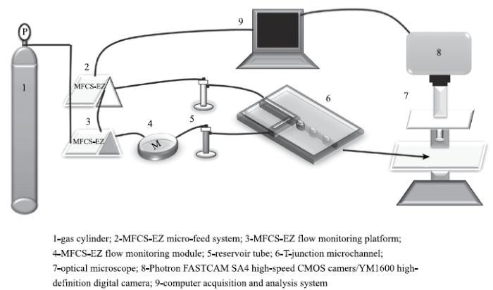
图1为实验装置的示意图.实验装置包含3个主要系统:微量进料及控制系统、T型微通道气液相分散系统和高速显微摄影系统.微量进料及控制系统由法国Fluigent公司的MFCS$^{\rm TM}$-EZ型微流体压力进样泵构成,包括压力驱动泵、流量测量模块和储液池.T型微通道气液相分散系统由苏州汶灏芯片科技有限公司提供的尺寸为22.5 mm×15.0 mm×4.0 mm的微芯片和芯片夹具组成.芯片的微通道为矩形截面,截面宽度为150μm,高度为50μm.高速显微摄影系统由上海上光新光学科技有限公司的XSZ型光学显微镜搭载日本PHOTRON公司的FASTCAM SA4高速摄像机组成,用于捕捉微通道内气液界面的时间序列图像.图1
 新窗口打开|下载原图ZIP|生成PPT
图1实验装置示意图
Fig.1Sketch of the experimental apparatus
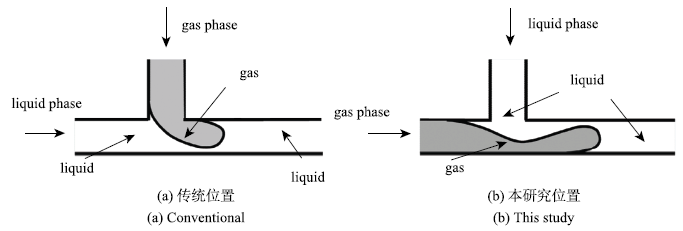
实验中,压缩空气作为分散相,添加表面活性剂的海藻酸钠溶液作为连续相.压缩空气由气瓶进入压力驱动泵和流量控制系统,通过两个储液池将气相和液相分别输入到T型微通道内.图2给出了传统气液两相进料位置及本实验中气液两相进料位置.本研究中,分散相气相从主通道进入,连续相液相由支路通道进入.实验过程中,通过微量进料及控制系统控制气相进气压力和液相入流流量,利用高速显微摄影技术和数字图像处理技术获得微通道内气液两相界面的变化,得到不同液相黏度和表面张力系数条件下的气液两相流型.所有实验均在室温22\textcelsius~和常压101.3 kPa条件下完成.
图2
 新窗口打开|下载原图ZIP|生成PPT
图2空气和溶液的入口位置
Fig.2Positions of gas and liquid input
2 实验结果与讨论
2.1 T型微通道内气液两相流型
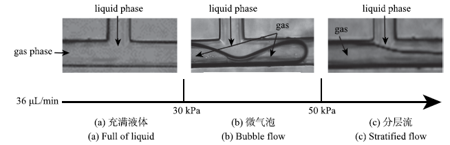
2.1.1 气液两相流型转变过程图3给出液相流率为36μL/min时,不同气相压力对应的气液两相流型.本研究主要观测到气泡流和分层流2种主要流型.虽然波状流在实验中也有出现,但由于其出现区间稳定性差,在此不予讨论.在T型微通道内通入液相,待通道内充满液相后,逐渐增大气相入口压力,通道内由充满液相向气泡流转变.当气相压力小于30 kPa时,气相在短时间内无法推动液体,微通道内一直充满液相(见图3(a)).直到气相压力超过30 kPa后,气相能够推动液相并逐渐进入微通道,在微通道的交汇处生成微气泡(见图3(b)).如果继续增大气相压力至50 kPa,微气泡将无法形成,气相和液相在微通道内分为两层,形成分层流(见图3(c)).
图3
 新窗口打开|下载原图ZIP|生成PPT
图3气液两相流型
Fig.3Gas-liquid two-phase flow pattern
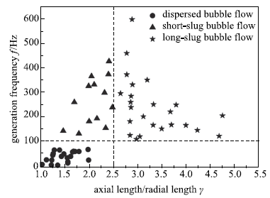
2.1.2 气泡流的区域划分
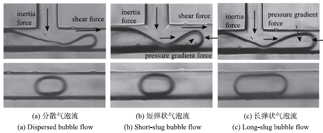
气泡流以生成范围宽、生成气泡尺寸均一、流动易控制等优势受到广泛关注.本研究发现,依据T型微通道内气泡的生成频率f和生成气泡的长径比$\gamma$将气泡流进一步细分为3种不同形式,分别为分散气泡流($f<100$ Hz,$\gamma <2.5$)、短弹状气泡流($f>100$ Hz,$\gamma <2.5$)和长弹状气泡流($f>100$ Hz,$\gamma >2.5$). 图4给出了调换传统进液和进气位置(见图2(b))后气泡流在微通道内生成微气泡的3种机制.Fu等[30]综述传统进气进液工况下(见图2(a))气泡生成机制时指出,迫使T型微通道内气泡断裂的作用力包括液相黏性剪切力和气泡上下游液相的压差力,二者的大小关系决定了气泡流的流型.而本文进气进液条件下,除了液相黏性剪切力和气泡上下游液相压差力的作用,液相惯性力作用同样重要.微通道内气泡的断裂和形成是在液相惯性力、黏性剪切力和气泡上下游液相压差力综合作用下克服表面张力束缚的结果.图4中上面的三幅图表示3种气泡流气泡断裂前气液两相的界面;对应的下面的三幅图分别表示3种气泡流气泡颈缩断裂后在主通道内形成的微气泡.微通道内分散气泡流和长弹状气泡流分别是基于剪切模式和挤压模式生成微气泡;而短弹状气泡流是基于过渡模式形成微气泡.如图4所示,在剪切模式下,气泡逐渐形成,在颈缩断裂之前仅占据小部分微通道的流通截面积,此时液相惯性力和黏性剪切力为控制气泡颈缩断裂的主要因素(见图4(a));在挤压模式下,气泡的前端填满整个通道,此时气泡上下游液相间的压差力和液相惯性力是气泡断裂的主要驱动力,液相黏性剪切力的作用可以忽略(见图4(c));而过渡模式介于剪切模式和挤压模式之间,气泡的前端占据大部分通道流通截面,主要驱动力是液相黏性剪切力、惯性力和气泡上下游液相间的压差力,并且三者作用相当(见图4(b)).
图4
 新窗口打开|下载原图ZIP|生成PPT
图4T型微通道内气泡生成机制
Fig.4Regimes for bubble formation in T-junction
图5给出不同气泡生成频率和气泡长径比下3种气泡流的区域.在固定液相流率的条件下,气相压力低时,通道连接处以剪切模式形成微气泡,在微通道内形成分散气泡流;气相压力高时,在通道连接处更易以挤压模式形成微气泡,此时在微通道内形成长弹状气泡流;而气相压力适中时,在通道连接处以过渡模式形成微气泡,微通道内形成短弹状气泡流.如图5所示,在分散气泡流区域内,微通道内气泡生成频率低,气泡尺寸小;在短弹状气泡流区域内,气泡生成频率高,气泡的总体平均尺寸比分散气泡流生成气泡的尺寸略大;而在长弹状气泡流区域,气泡生成频率高、尺寸大.
图5
 新窗口打开|下载原图ZIP|生成PPT
图5不同类型气泡流的区域划分
Fig.5Different flow patterns for bubble flows
2.2 液相物性对气液两相流型的影响
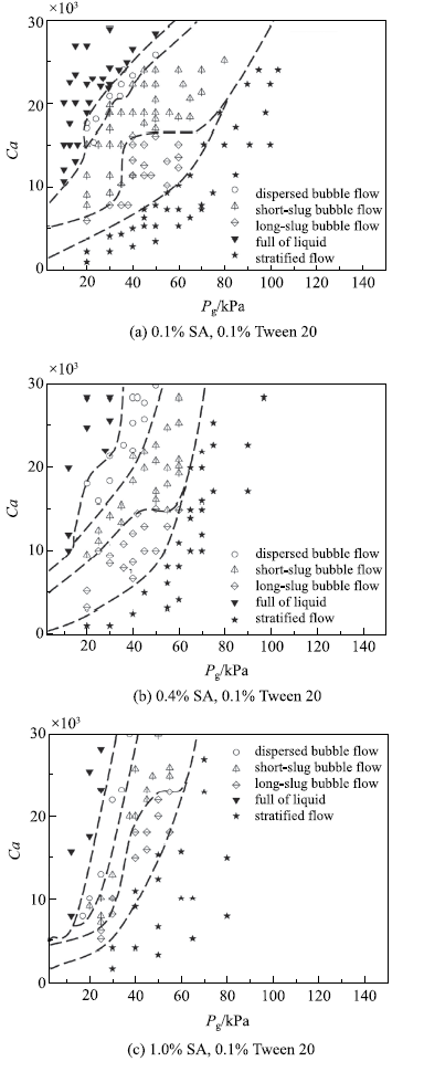
2.2.1 液相黏度对流型的影响以含0.1%表面活性剂吐温20的海藻酸钠溶液(质量分数分别为0.1%,0.4%和1.0%)作为液相,考察液相黏度对气液两相流型的影响.由表1可知,随着海藻酸钠溶液质量分数的增加,液相黏度由1.58 mPa$ \cdot$s增大至6.60 mPa$ \cdot$s,而溶液表面张力系数的变化基本可以忽略.图6表示不同液相黏度条件下微通道内气液两相流型随液相毛细数$Ca$和气相压强$P_{\rm g}$的分布. 毛细数$Ca$定义为
式中,$\mu$$_{\rm l}$是连续相液相的黏度,$\sigma$是表面张力系数,$v_{\rm l}$是连续相液相的流率.从图6可以看出,随着液相黏度的增大,微通道内气泡流的范围不断减小,液相的黏度对通道内气泡的生成影响较大.分析其原因,随着液相黏度的增加,在相同气液流动参数条件下,黏性剪切力占据克服表面张力作用的比重增大,加速气泡的断裂脱离过程,导致在较小的气相压力下气相就会发生断裂生成气泡.此外,从图6(a)还可以看出,当液相黏度相对较小时,剪切模式下形成的分散气泡流发生在毛细数$Ca$相对较大的工况下,而挤压模式下形成的长弹状气泡流则更易发生于毛细数$Ca$相对较小的工况.然而,随着液相黏度的增大(见图6(b)和图6(c)),这种趋势越来越不明显.这是因为在剪切模式下,随着液相黏度的增大,液相对气泡的黏滞剪切力增大,液相在相对较小的流速下就可以使气泡颈缩断裂,从而导致毛细数$Ca$不断降低;而在挤压模式下,随着液相黏度的增大,微通道壁面与气泡间液膜的黏滞阻力增大,液相需要在相对较大的流速下才能使气弹发生颈缩断裂形成微气泡, 由此造成毛细数$Ca$不断增大.
图6
 新窗口打开|下载原图ZIP|生成PPT
图6液相黏度对气液两相流型的影响
Fig.6Influence of liquid viscosity on gas-liquid two-phase flow pattern
2.2.2 表面张力对流型的影响
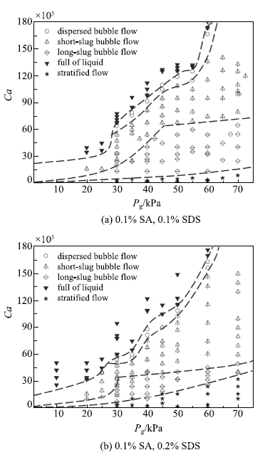
以含表面活性剂SDS(质量分数分别为0.1%和0.2%)的质量分数为0.1%的海藻酸钠溶液作为液相,考察液相表面张力系数对气液两相流型的影响.如表1所示,海藻酸钠溶液中表面活性剂SDS的质量分数由0.1%增大至0.2%,溶液的表面张力系数由24.50 mN/m增大至31.59 mN/m,而溶液的黏度没有发生改变.图7表示不同表面张力系数条件下微通道内气液两相流型随液相毛细数$Ca$和气相压强$P_{\rm g}$的分布.由图7可知,随着表面张力系数的增大,微通道内气泡流的生成范围略有减小,而短弹状气泡流和长弹状气泡流的生成范围占气泡流总体的生成范围的比例变化明显,当毛细数$Ca$相对较小时气泡流即由过渡模式进入挤压模式.这说明溶液表面张力系数对气泡流总体操作范围的影响相对较小,而主要影响短弹状气泡流和长弹状气泡流在整体气泡操作范围内的占比.分析其原因:在过渡模式下形成短弹状气泡流,需要黏性剪切力、气泡上下游压差力和液相惯性力共同作用克服表面张力;在过渡模式和挤压模式的临界处,黏性剪切力的作用为零,气泡上下游压差力基本保持不变,而表面张力增加量则需要通过增大液相流速来克服;由于惯性力与液相流速的平方成正比,因此随着表面张力系数的增大,短弹状气泡流和长弹状气泡流的边界处的临界毛细数将减小.
图7
 新窗口打开|下载原图ZIP|生成PPT
图7表面张力系数对气液两相流型的影响
Fig.7Influence of surface tension coefficients on gas-liquid two-phase flow pattern
2.3 不同类型气泡流分区边界的拟合
根据Rodriguez-Rodriguez等[31]的研究,微气泡形成过程中其内部气体压力梯度可忽略,认为其内部压力均一,气泡生成过程可以利用Rayleigh-Plesset方程进行描述式中,$\rho$$_{\rm l}$是液相密度,$\mu$$_{\rm l}$是液相黏度,$\sigma$是表面张力系数,$P_{\rm l}$是液相压力,$P_{\rm g}$是气相压力,$R_{\rm b}$是气泡半径. 式(2)还可表达为
式中,d为气泡直径,$v_{\rm l}$为连续相流率. 基于π定理量纲分析可得
式中
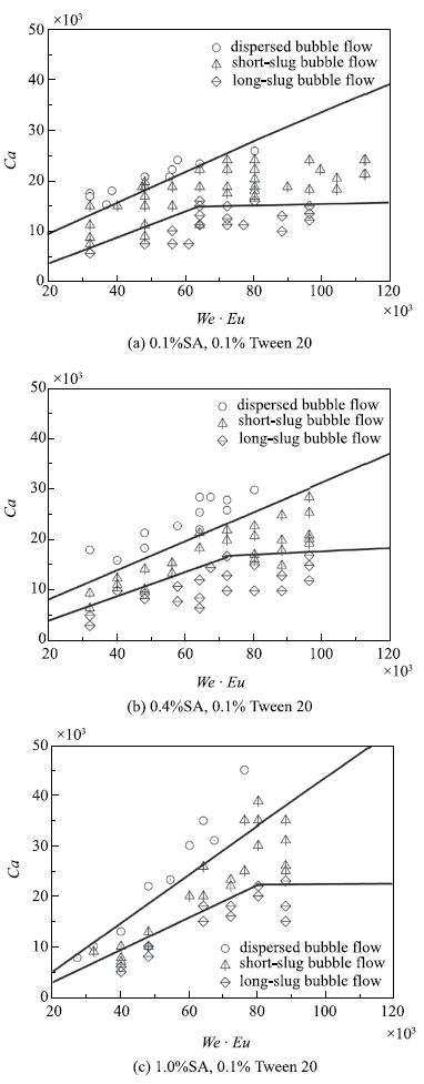
由文中第2.1.2节可知,在当前的进气进液条件下,气泡流具有3种不同类型,影响微通道内气泡流类型划分的主要作用力包括液相惯性力、黏性剪切力以及气泡上下游液相压差力,三者共同作用克服表面张力.为了明确不同类型气泡流的分区界线,选用式(1),式(5)和式(6)三个无量纲数描述这些力间的相对关系.图8给出了含0.1 %表面活性剂吐温20的海藻酸钠溶液中不同类型气泡流的转变边界.在当前实验工况下满足$0.02<We \cdot Eu<0.12$时,分散气泡流与短弹状气泡流分界线为
式中,$\alpha$ = $\mu$$_{\rm l}$/$\mu$$_{\rm g}$,$\mu$$_{\rm g}$为分散相黏度.短弹状气泡流与长弹状气泡流的线性边界斜线部分为
短弹状气泡流与长弹状气泡流的线性边界水平线部分为
图8
 新窗口打开|下载原图ZIP|生成PPT
图8含表面活性剂吐温20的海藻酸钠溶液中不同类型气泡流转变边界
Fig.8Flow pattern transition boundaries of sodium alginate solution with Tween 20
由图8可知,毛细数$Ca$相对较大时,易于形成分散气泡流,此时黏性剪切力的作用相对较大;毛细数$Ca$相对较小时,易于形成长弹状气泡流,此时黏性剪切力的作用相对较小.黏性剪切力作用相对较大时,剪切力和压差力的比值低于一定值(等于分散气泡流与短弹状气泡流分界线斜率),气泡流由分散气泡流转变为短弹状气泡流.而黏性剪切力作用相对较小时,当压差力相对表面张力的占比(等于$We\cdot Eu$)低于一定值,且剪切力和压差力比值低于某一定值(等于短弹状气泡流与长弹状气泡流分界线斜率),气泡流将由短弹状气泡流转变为长弹状气泡流;当压差力相对表面张力的占比(等于$We\cdot Eu$)高于此定值,黏性剪切力的作用相比压差力可以完全忽略,此时黏性剪切力的改变对短弹状气泡流转变为长弹状气泡流没有任何影响,短弹状气泡流转变为长弹状气泡流的边界变为水平线.基于上述不同类型气泡流的分界,可以在给定液相黏度和表面张力系数的前提下,确定不同类型气泡流的具体生成范围,实现微通道生成微气泡过程的可控操作.
3 结 论
利用高速显微摄影技术和数字图像处理技术对T型微通道内气液两相流型进行了实验研究和定量分析,结论如下:(1)依据微通道内气泡的生成频率和生成气泡的长径比气泡流可细分为3种.其中,分散气泡流基于剪切模式生成微气泡,气泡生成频率低,气泡长径比小;长弹状气泡流基于挤压模式生成微气泡,气泡生成频率高,气泡长径比大;短弹状气泡流基于过渡模式生成微气泡,气泡生成频率高,气泡长径比小.
(2)液相的黏度对通道内气泡流的整体生成范围影响较大,随着液相黏度的增大,微通道内气泡流的生成范围不断减小;液相表面张力系数对气泡生成的生成范围影响相对较小.
(3)基于无量纲数毛细数$Ca$、韦伯数$We$和欧拉数$Eu$划分不同类型气泡流的分界线,得到不同类型气泡流的生成范围,以实现微通道生成微气泡过程的可控操作.
参考文献 原文顺序
文献年度倒序
文中引用次数倒序
被引期刊影响因子
DOIURLPMID [本文引用: 1]

Abstract Recent advances in the fabrication of microflow devices using micro-electromechanical systems (MEMS) technology are described. Passive and active liquid flow control and particle-handling methods in micrometer-scale channels are reviewed. These methods are useful in micro total analysis systems ( TAS) and laboratory-on-a-chip systems. Multiple flow control systems (i.e., arrayed microvalves) for advanced high-throughput microflow systems are introduced. Examples of microflow devices and systems for chemical and biochemical applications are also described.
DOIURLPMID [本文引用: 1]
Abstract Ultrasound application combined with microbubbles has shown great potential for intracellular gene delivery. However, the fundamental mechanistic question of how plasmid DNA enters the intracellular space mediated by ultrasound and microbubble has not been fully explored and understood. The goal of this study is to unveil the detailed intracellular uptake process of plasmid DNA stimulated by ultrasound and microbubbles, uniquely highlighting the role of microbubbles play in this process. The usage of targeted microbubbles pinpointed the subcellular membrane site, where ultrasound exerted acoustic force onto the cell membrane. With the combination of high-speed video microscopy and 3D confocal fluorescence microscopy, we show the spatiotemporal correlation between the microbubble dynamics and intracellular plasmid DNA distribution. Two ultrasound modes (high pressure short pulse and low pressure long pulse) were chosen to trigger different plasmid DNA uptake routes. We found that reversible cell membrane disruption, induced by high pressure short pulse ultrasound, permitted plasmid DNA passage across cell membrane, but not in an exclusive way. Under both ultrasound modes, with or without cell membrane disruption, global plasmid DNA internalization, even nuclear-localization, was observed immediately post ultrasound application. Our results show that plasmid DNA uptake evoked by localized acoustically excited microbubbles is a fast (<2min), global (not limited to the site where microbubbles were attached), and multi-mechanisms involved process.
DOIURL
细胞培养液在微流控生物反应器中受到外界物理场(如压力梯度或者电场)作用流动而产生流体剪应力,并进一步刺激种子细胞调控其内部基因的表达,从而促进细胞的分化和生长,这个过程在自然生命组织内的微管中亦是如此.考虑到细胞培养微腔隙中液体流动行为很难实验量化测定,理论建模分析是目前可行的研究手段.因此建立了矩形截面的细胞微流控培养腔理论模型,将外部的物理驱动场(压力梯度与电场)与培养腔内液体的流速、切应力和流率联系起来,分别得到了压力梯度驱动(pressure gradient driven,PGD)、电场驱动(electric field driven,EFD)及力–电协同驱动(pressure-electricity synergic driven,P-ESD)三种驱动方式下的液体流动理论模型.结果表明该理论模型与现有的实验结果基本一致,即力–电协同作用下的解答为压力梯度驱动和电场驱动结果的叠加.细胞培养腔内的流体流速、剪应力及流率幅值均正比于外部物理场强幅值,但随着压力梯度驱动载荷频率的增大而减小,随着电场驱动频率的变化不明显.在压力梯度驱动作用下,细胞贴壁处的切应力随着腔高的增大而线性增大,流率则随着腔高的增大而非线性增大,而电场驱动下的结果不受腔高的影响.生理范围内的温度场变化对压力和电场驱动的结果影响不大.另外,在引起细胞响应的流体切应力水平,电场驱动能提供较大的切应力幅值而压力梯度驱动则能提供较大的流率幅值.该理论模型的建立为细胞微流控生物反应器实验系统的设计及参数优化提供理论参考,同时也为力–电刺激细胞生长、分化机理的研究的提供基础.
[本文引用: 1]
[本文引用: 1]
DOIURL
We provide a detailed physical description of the bubble formation processes taking place in a type of flow where the liquid pressure gradient can be straightforwardly controlled. The analysis, which is supported by an exhaustive experimental study in which the liquid viscosity is varied by three orders of magnitude, provides closed expressions for both the bubbling frequencies and the bubble diameters. Different equations are obtained depending on the values of the three dimensionless parameters characterizing this physical situation, namely the Weber and Reynolds numbers and the gas to liquid flow rate ratio. Since both the inertia dominated and viscous dominated bubbling regimes are simply described in terms of the local pressure gradient and the flow rate ratio, the same types of ideas can be applied in the design of bubble makers in which the pressure gradients are controlled in completely different ways.
DOIMagsci
<p>流动聚焦型微流控装置能够方便、高效地生成均一度好且大小精确可调的微液滴(气泡),故被广泛应用于颗粒材料合成、药物封装、细胞培养等诸多领域. 进一步优化通道结构有助于实现对合成微粒粒径、均一度和尺寸范围的精确调控. 本文数值研究了通道深度、缩颈段长度以及两相夹角等几何构型因素对流动聚焦生成微液滴直径及其生成周期各个阶段的影响. 控制液滴生成方式为滴流式,发现液滴直径随通道深度d 的增加近似呈线性增大,且当通道深度小于30 μm 时,随着通道深度的下降,微液滴生成周期在毛细力的强烈作用下出现骤升,通道深度超过80 μm 时,微液滴的生成周期基本接近恒定. 连续相和离散相的夹角<em>θ</em>接近90°时,液滴直径及其生成周期最短,夹角太大或太小均不利于生成均一度好且粒径微小可控的液滴. 调整缩颈段长度<em>l</em>引起液滴直径及其生成周期的变化幅度仅为其平均值的3%~5% 左右. 此外,缩颈段宽度也是影响流动聚焦生成微液滴直径及其生成周期的重要因素,在通道深度固定时,缩颈段越宽,微液滴直径及其生成周期越大.</p>
DOIURLPMID
Current microbubble-based ultrasound contrast agents are administered intravenously resulting in large losses of contrast agent, systemic distribution, and strict requirements for microbubble longevity and diameter size. Instead we propose in situ production of microbubbles directly within the vasculature to avoid these limitations. Flow-focusing microfluidic devices (FFMDs) are a promising technology for enabling in situ production as they can produce microbubbles with precisely controlled diameters in real-time. While the microfluidic chips are small, the addition of inlets and interconnects to supply the gas and liquid phase greatly increases the footprint of these devices preventing the miniaturization of FFMDs to sizes compatible with medium and small vessels. To overcome this challenge, we introduce a new method for supplying the liquid (shell) phase to a FFMD that eliminates bulky interconnects. A pressurized liquid-filled chamber is coupled to the liquid inlets of an FFMD, which we term a flooded FFMD. The microbubble diameter and production rate of flooded FFMDs were measured optically over a range of gas pressures and liquid flow rates. The smallest FFMD manufactured measured 14.5 times 2.8 times 2.3 mm. A minimum microbubble diameter of 8.1 +or- 0.3 mum was achieved at a production rate of 450,000 microbubbles/s (MB/s). This represents a significant improvement with respect to any previously reported result. The flooded design also simplifies parallelization and production rates of up to 670,000 MB/s were achieved using a parallelized version of the flooded FFMD. In addition, an intravascular ultrasound (IVUS) catheter was coupled to the flooded FFMD to produce an integrated ultrasound contrast imaging device. B-mode and IVUS images of microbubbles produced from a flooded FFMD in a gelatin phantom vessel were acquired to demonstrate the potential of in situ microbubble production and real-time imaging. Microbubble production rates of 222,000 MB/s from a flooded FFMD within the vessel lumen provided a 23 dB increase in B-mode contrast. Overall, the flooded design is a critical contribution towards the long-term goal of utilizing in situ produced microbubbles for contrast enhanced ultrasound imaging of, and drug delivery to, the vasculature.
DOIURL
Fabrication of micro-devices for small bubble and droplet generation is usually tedious or costly. Here we present a simple capillary-assembled micro-device by modifying the capillary embedded stepT-junction microchannel. Besides a capillary in the side channel, another same size capillary is placed at the downstream ofT-junction. The two vertically embedded capillaries inherently guarantee the device symmetry by forming an arch orifice. And it could be applied to both L/L and G/L micro-dispersion with focused continuous phase flows. Monodispersed small bubbles of 35 m (CV=3.52%) and droplets of 15 m (CV=2.12%) are generated with stable flow-focusing jetting regime, by thin jets deriving from the large interface and arch orifice in the device. A general bubble and droplet size scaling law is obtained, and it could predict the bubble and droplet size very well. The device could provide a more convenient approach for adjusting bubble and droplet sizes than usual methods. The device shows its significant advantages of easy assembly, low cost and high versatility for both small bubble and droplet generation.
DOIURL
DOIURL [本文引用: 1]
This paper introduces an experimental study on the microbubble generation mechanism in a coflowing microfluidic device. Using propane, butane and air as the dispersed phases and different SDS-PEG solutions as the continuous phases, two kinds of bubble generating phenomena, named "single-bubble generation" flow and "dual-bubble generation" flow, were observed in experiment and uniform bubbles with average diameters ranging from 391 mu m to 713 mu m and polydispersity less than 2.9% were successfully prepared. The pressure fluctuation of gas phase is carefully analyzed with the Young-Laplace equation and the bubble generation mechanism is summarized from the dynamic movement of gas-liquid interface. The main factors impacting the bubble size variation are illustrated for both the organic and inorganic gases. A universal correlation is established to predict the average bubble diameters. (C) 2013 Elsevier Ltd. All rights reserved.
DOIURL [本文引用: 1]
The aim of this study was to investigate the effect of operating parameters such as liquid flow rate, gas inlet pressure, and capillary diameter as well as the influence of the physical properties of the liquid, in particular viscosity, on the generation of monodisperse microbubbles in a circular cross section T-junction device. Aqueous glycerol solutions with viscosities ranging from 1- to 100 mPa s were used in the experiments. The bubble diameter generated was studied for systematically varied combinations of gas inlet pressure, liquid flow rate, and liquid viscosity with a fixed capillary inner diameter of 150 mu m for the liquid and gas inlet channels as well as the outlet channel. In addition, the effect of channel geometry on bubble size was studied using capillaries with inner diameters of first 100 and then 200 mu m. In all the experiments the distance between the coaxial capillaries at the junction was set to be 200 mu m. All the microbubbles produced in this study were highly monodisperse (polydispersity index < 1 %) and it was found, as expected, that bubble formation and size were influenced by the ratio of liquid to gas flow rate, capillary size, and liquid viscosity. The experimental data were then compared with empirical scaling laws derived for rectangular cross-section junctions. In contrast with these previous studies, which have found bubble size to be dependent on either the flow rate ratio (the squeezing regime) or capillary number (the dripping regime), in this experimental study bubble size was found to depend on both capillary number and flow ratio.
DOIURL
This paper describes two-phase flow pattern and pressure drop characteristics during the absorption of CO 2 into water in three horizontal microchannel contactors which consist of Y-type rectangular microchannels having hydraulic diameters of 667, 400 and 200 m, respectively. With the help of a high-speed photography system, flow patterns such as bubbly flow, slug flow (including two sub-regimes, Taylor flow and unstable slug flow), slug-annular flow, churn flow and annular flow were observed in these microchannels. The applicability of the currently available correlations for describing flow pattern transitions in microchannels has been examined. Generally, the predicting performance of these correlations deteriorates as the channel diameter further reduces. Toward solving this discrepancy, an empirical correlation based on the superficial Weber numbers was developed to interpret the transition from Taylor flow to unstable slug flow in three microchannels. Taylor bubble formation process in microchannels was found to be in the squeezing regime at lower superficial liquid velocities ( Ca ranging from 0.0019 to 0.029) while the transition to the dripping regime was observed at the highest superficial liquid velocity of 1.0 m/s. Lengths of Taylor bubbles formed in the squeezing regime can be well represented by the scaling relation proposed by Garstecki et al. [Formation of droplets and bubbles in a microfluidic T-junction caling and mechanism of break-up. Lab on a Chip, 6, 437 446]. For flow patterns including slug-annular flow, annular flow and churn flow, a simple analysis based on the separated flow model has been performed in order to reveal the observed effect of the superficial liquid velocity on two-phase frictional multiplier in the present microchannels. Then, reasonable correlations for the prediction of two-phase frictional pressure drop under these flow patterns were suggested.
DOIURL
Over the past few decades an enormous interest in two-phase flow in microchannels has developed because of their application in a wide range of new technologies, ranging from lab-on-a-chip devices used in medical and pharmaceutical applications to micro-structured process equipment used in many modern chemical plants. Taylor flow, in which gas bubbles are surrounded by a liquid film and separated by liquid plugs, is the most common flow regime encountered in such applications. This review introduces the important attributes of two phase flow in microchannels and then focuses on the Taylor flow regime. The existing knowledge from both experimental and computational studies is presented. Finally, perspectives for future work are suggested.
DOIURL
Multiphase chemical microreactors require a detailed knowledge of the flow conditions inside the reaction system. This paper reports flow visualization measurements of the two-phase gas–liquid flow pattern and the liquid velocity distribution inside liquid plugs of an intermittent flow. Rectangular cross-section silicon microchannels with hydraulic diameters between 187.5 and 218 μm are fabricated. Laser Induced Fluorescence (LIF) is used to determine the flow pattern. To analyze the influence of the liquid properties and the channel diameter on the two-phase flow pattern, we present flow regime maps using different channel geometries and fluids. A universal flow pattern map based on dimensional analysis is presented. In contrast to microchannel flows, a great number of correlations for flow characteristics for multiphase flow in (round) pipes with diameters >1 mm exist. We compare our experimental results from optical flow visualizations in microreactors with common flow correlations and regime maps for macro- and microchannels. The recirculation motion in the liquid segments of an intermittent gas–liquid flow is analyzed using micron-resolution particle image velocimetry (μPIV). The velocity distribution influences the mixing and the mass transport towards the reactive phase interface dealing with two-phase chemical reactions. For straight microchannels hardly any mass transport over the center line is quantified. For enhanced mixing geometrical adaptations are suggested.
DOIURLMagsci
<p>利用显微粒子图像测速技术、高速度数码显微系统及数值模拟方法研究了Y 型微通道内液滴的形成. 主要考虑了Y 型角度(45°,90°,135°,180°)、两相流量大小等因素的影响. 发现在挤压机制中,Y 型微通道内分散相液滴的形成主要受到来自连续相的剪切作用,Y 型角度越小,分散相所受到的剪切作用越大. 在液滴生成过程中,连续相速度剖面呈非对称抛物线型分布. 当Y 型角度小于180°时,角度的变化对液滴直径大小影响较小,但角度的减小会加快液滴的生成时间. 当Y 型角度为180°时,生成的液滴体积最大且生成时间最长. 毛细数对液滴直径和生成时间的变化同时产生影响,连续相毛细数的增大使得连续相在两相交汇位置处对分散相的作用力更集中,导致分散相更易破裂.</p>
DOIURL
The aim of this work is to investigate the bubble formation in non-Newtonian fluids in a microfluidic T-junction by crossflowing rupture technique, using a high-speed digital camera. Experiments were conducted in a glass microchannel with 120 μm wide and 40 μm deep. N 2 bubbles were generated in different concentrations of polyacrylamide (PAAm) solutions. Various flow patterns were observed at the T-junction by varying gas and liquid flow rates. The breakup mechanism for bubbles was investigated to gain insight into the effects of flow rates and concentrations of PAAm solutions on bubble size. The gaseous thread collapses at a constant speed in the collapse stage; while during the final pinch-off stage, the variation of the minimum width W m of the gaseous thread with the remaining time ( T 61 t) could be scaled as W m 65 ( T 61 t) 0.21. The bubble size increases non-linearly with the gas/liquid flow rates ratio, and decreases with the concentration of PAAm solutions.
DOIURL [本文引用: 1]
正微流控技术及微流控器件是近年来发展迅速的多学科交叉研究领域,相比于传统方法,微流控技术能够实现对微量多相流体的精准操控,可应用于化学分析、先进材料合成、蛋白质结晶、单细胞培育及检测、信息处理等领域。该文回顾微流控器件中的多相流动现象,概述其所涉及的流体力学机理,阐述实现多相微流控的各种方法,并分析多相微流控技术的应用现状及面临的挑战,最后总结针对多相微流动问题的数值模拟方法和实验测量技术,展望多相微流控器件的研究方向及应用前景。
DOIURL [本文引用: 1]
正微流控技术及微流控器件是近年来发展迅速的多学科交叉研究领域,相比于传统方法,微流控技术能够实现对微量多相流体的精准操控,可应用于化学分析、先进材料合成、蛋白质结晶、单细胞培育及检测、信息处理等领域。该文回顾微流控器件中的多相流动现象,概述其所涉及的流体力学机理,阐述实现多相微流控的各种方法,并分析多相微流控技术的应用现状及面临的挑战,最后总结针对多相微流动问题的数值模拟方法和实验测量技术,展望多相微流控器件的研究方向及应用前景。
URL [本文引用: 1]
DOIURL [本文引用: 1]
Experimental results of flow pattern for air-water horizontal flow in capillary tubes are reported and flow pattern regime maps are presented at different pressures (from 1 MPa up to 5 MPa). In addition, theoretically based transition criteria for the flow pattern (derived from literature) are presented. The experimental results and theory seem to match each other fairly well. Again, it has been shown that two-phase capillary flow can reasonably simulate a microgravity “equivalent system” under normal earth conditions.
DOIURL [本文引用: 1]
Two-phase (air-water) flow experiments were conducted in artificial horizontal fractures (narrow channels). Two experimental set-ups were utilized. One set of experiments was performed by using two glass plates (1 0.5 m) with a gap width of 1 mm. The second set of experiments was performed using two bricks made of baked clay (28 14 cm) for which three gap widths of h 1 = 0.54 mm, h 2 = 0.40 mm and h 3 = 0.18 mm have been tested. Air and water were injected separately, through alternating capillary tubes for the first set-up and through a porous medium for the second. For each experiment, the fracture was initially saturated at constant water flow-rate, and air injection was then started. When steady state was reached, pressure drop and liquid volume fraction were measured. Then, air injection was increased stepwise and the experiment was repeated at different liquid flow rates. By varying the flow rates of each fluid phase, different flow structures were observed for the glass channel experiment: bubbles, fingering bubbles, complex, annular and droplet flow. These flow structures show more similarity to those observed in pipes than to those expected in porous media. Using the formalism developed for two-phase flow in pipes, and by taking experimental observations into account, a theoretical relationship for the two-phase pressure gradient is proposed. This relationship is evaluated with experimental data. Then, the results are analyzed with three models. First, the Lockhart & Matinelli model gives a good fit for both pressure drop and liquid volume fraction against the Martinelli parameter. Second, by considering the two phases flowing in the fracture as a single phase with averaged properties, the appropriate friction factor and Reynolds number of the mixture are defined. This model, which is similar to the homogeneous model, permits the selection of the experimental data corresponding to laminar flow. Finally, by using the generalized Darcy model, it was found that for laminar flow, the liquid-phase relative permeability is equal to the liquid volume fraction, while the gas-phase relative permeability is not a linear function of the liquid volume fraction.
DOIURL [本文引用: 1]
Various flow pattern maps for two-phase gas iquid flow in horizontal pipes are tested against the 5935 flow pattern observations presently contained in the UC Multiphase Pipe Flow Data Bank. A new flow regime correlation representing an extension of the work done by Govier and Aziz [3] is presented and is shown to be in better agreement with the data than the other correlations tested. A computer program for this correlation is included. It is also shown that there is no significant improvement obtained by including the effects of the physical properties of the fluids using any of the physical property parameters which have been proposed so far.
DOIURL [本文引用: 1]
For a simple biphasic hydrolysis, we show that the application of various reaction conditions in microreactors using segmented flow can dramatically increase the reaction rate. A tandem diazotation/Heck reaction served as an example that even homogeneous reactions can be accelerated by segmentation in microreactors.
DOIURL [本文引用: 1]
The technology needed to produce structures at micro scales has improved significantly over the past few years. This has opened up new opportunities for engineering compact, efficient fluid flow systems on a micro scale. Small channels created within the microprocessors automatically involve very short diffusion, conduction and mixing path lengths, so that mass, heat and momentum transfer rates are extremely high. This allows microreactors to be produced which exert close control over stream temperatures and compositions, even for very rapid reactions. A further benefit of microengineering will come from the ability to integrate the control devices and sensors into a single unit and the combination of different units into a complete compact chemical processing system. Ultimately microengineering is another arm of process intensification and as such should considerably enhance the reduction of plant size and the improvement of plant safety.
DOIURLPMID [本文引用: 1]
Abstract A multiphase microreactor based upon the use of slug flow through a narrow channel has been developed. The internal circulation, which is stimulated within the slugs by their passage along the channel, is responsible for a large enhancement in the interfacial mass transfer and the reaction rate. Mass transfer performance data has been obtained for a glass chip-based reactor in a 380 microm wide channel by monitoring the extraction of acetic acid from kerosene slugs as they moved along the reactor channel. Finally, the data was compared with that provided from other inter-phase contacting techniques.
DOIURL [本文引用: 1]
In this work, the flow of immiscible fluids in a PMMA microchannel 300 m wide and 600 m deep was investigated experimentally. Dyed de-ionized water and kerosene were selected as the test fluids. Flow patterns were observed by using a CCD camera and were identified by examining the video images. Flow patterns obtained at the T-junction and in the microchannel are presented. Superficial velocities varied between 9.26 × 10⁻⁴ 1.85 m/s for water and 9.26 × 10⁻⁴ 2.78 m/s for kerosene. The formation mechanism of slug, monodispersed droplet and droplet populations at the T-junction was studied. Weber numbers of water and kerosene, WeKS and WeWS, were used to predict the flow regime transition and the flow patterns map. The experimental data of volume of dispersed phase were successfully correlated as a function of WeKS, WeWS, and hold-up fraction. Considering the uncertainty associated with experimental quantification of the process, the results are in satisfactory agreement over the wide range of 1.90 × 10⁻³ < WeWS < 30.43 and 5.90 × 10⁻⁶ < WeKS < 0.13 with average absolute deviation of only 16.18%. 08 2006 American Institute of Chemical Engineers AIChE J, 2006
DOIURL [本文引用: 1]
We describe the results of a numerical investigation of the dynamics of breakup of streams of immiscible fluids in the confined geometry of a microfluidic T-junction. We identify three distinct regimes of formation of droplets:squeezing, drippingandjetting, providing a unifying picture of emulsification processes typical for microfluidic systems. The squeezing mechanism of breakup is particular to microfluidic systems, since the physical confinement of the fluids has pronounced effects on the interfacial dynamics. In this regime, the breakup process is driven chiefly by the buildup of pressure upstream of an emerging droplet and both the dynamics of breakup and the scaling of the sizes of droplets are influenced only very weakly by the value of the capillary number. The dripping regime, while apparently homologous to the unbounded case, is also significantly influenced by the constrained geometry; these effects modify the scaling law for the size of the droplets derived from the balance of interfacial and viscous stresses. Finally, the jetting regime sets in only at very high flow rates, or with low interfacial tension, i.e. higher values of the capillary number, similar to the unbounded case.
DOIURL [本文引用: 1]
In this work, we have systematically analyzed the scaling law of droplet formation by cross-flow shear method in T-junction microfluidic devices. The droplet formation mechanisms can be distinguished by the capillary number for the continuous phase (Cac), which are the squeezing regime (Cac < 0.002), dripping regime (0.01 < Cac < 0.3), and the transient regime (0.002 < Cac< 0.01). Three corresponding correlations have been suggested in the different range of Cac. In the dripping regime, we developed a modified capillary number for the continuous phase (Cac′) by considering the influence of growing droplet size on the continuous phase flow rate. And the modified model could predict droplet diameter more accurately. In the squeezing regime, the final plug length was contributed by the growth and ‘squeeze’ stages based on the observation of dynamic break-up process. In the transient regime, we firstly suggested a mathematical model by considering the influences of the above two mechanisms. The correlations should be very useful for the application of controlling droplet size in T-junction microfluidic devices.
DOIURL [本文引用: 1]
The aim of this paper is to investigate the squeezing-to-dripping transition for bubble formation in a microfluidic T-junction by cross-flowing rupture technique using a high-speed digital camera. Experiments were conducted in a glass microfluidic T-junction with the cross-section of the microchannel of 120 μm wide and 40 μm deep. N 2 bubbles were generated in glycerol–water mixtures with several concentrations of surfactant sodium dodecyl sulfate (SDS). Three different regimes were identified for generating different kinds of bubbles: squeezing, dripping and transition regimes. Various forces exerted on the gaseous thread in different regimes were analyzed. Long slug bubbles were formed in the squeezing regime, while dispersed bubbles in the dripping regime. The transition regime formed short slug bubbles. The bubble sizes in various regimes could be correlated with several dimensionless numbers such as the ratio of gas/liquid flow rates and capillary number. The two-step model for droplets ( Steegmans et al., 2009) was extended to describe the bubble formation.
DOIURL [本文引用: 1]
61Bubble formation and breakup dynamics in confined spaces are reviewed.61Effects of the confinement and the fluid flow on bubble dynamics are highlighted.61Dynamical evolution of the gas–liquid interface is analyzed.61Scaling laws for the bubble size are reviewed.61Scaling-up of bubble generation in microdevices are presented.
DOIURL [本文引用: 1]
We provide a comprehensive and systematic description of the diverse microbubble generation methods recently developed to satisfy emerging technological, pharmaceutical, and medical demands. We first introduce a theoretical framework unifying the physics of bubble formation in the wide variety of existing types of generators. These devices are then classified according to the way the bubbling process is controlled: outer liquid flows (e.g., coflows, cross flows, and flow-focusing flows), acoustic forcing, and electric fields. We also address modern techniques developed to produce bubbles coated with surfactants and liquid shells. The stringent requirements to precisely control the bubbling frequency, the bubble size, and the properties of the coating make microfluidics the natural choice to implement such techniques.
