全文HTML
--> --> --> 图 1 (a) Engin-X高温炉加热单元实物图; (b) Engin-X高温炉加热单元简化图
Figure1. (a) Engin-X furnace heating unit current layout; (b) Engin-X furnace heating unit simplified schematic drawing.
图2为Engin-X高温原位实验设备布置示意图, 共设有两组中子探测器, 以中子入射方向为参考方向(垂直纸面向内), 探测器分别位于 ± 90°位置, 探测器在垂直方向覆盖范围为 ± 21°[15], 故要求高温炉半椭圆反射罩需为衍射中子预留至少42°的衍射覆盖角, Engin-X实际留有约60°的衍射覆盖角, 整套加热装置由PRECISION CONTROL SYSTEMS公司研制[16]. 为进一步提升加热温度, 本文从反射罩结构、布局、反射涂层以及衍射覆盖角等方面着手优化设计.
 图 2 Engin-X高温原位实验设备布置示意图
Figure2. Engin-X setup for in-situ high temperature experiments.
3.1.反射罩结构设计
采用两种结构设计, 椭圆-圆组合反射罩和椭圆-圆-椭圆组合反射罩, 相似的几何设计理念在专利“一种基于双反射罩的均匀照明系统”中也有体现[17]. 椭圆-圆组合反射罩及其几何特征如图3(a)所示, 灯管位于椭圆第一焦点处, 样品位于椭圆第二焦点处, 并以灯管中心为圆心、灯管至椭圆弧边缘点距离为半径作两段对称圆弧, 同时满足椭圆弧边缘点、圆弧边缘点和样品中心点三点共线以实现较优光线出射量. 要确定椭圆-圆组合反射罩的最优形状, 需要设定四个变量, 包括椭圆第一焦距L1、第二焦距L2、椭圆弧深度D以及切线夹角θ, 对反射罩几何形状进行设定. Engin-X现有高温炉衍射覆盖角可由60°缩小至55°, 对四反射罩布局而言, 可推算出θ取值应为
 图 3 (a)椭圆–圆组合反射罩几何关系图; (b)椭圆–圆–椭圆组合反射罩几何关系图
Figure3. (a) Combined ellipse-sphere reflector geometrical layout; (b) combined ellipse-sphere-ellipse reflector geometrical layout.
椭圆-圆-椭圆组合反射罩及其几何特征如图3(b)所示, 外椭圆第一焦点与内椭圆第一焦点重合, 外椭圆第二焦点与内椭圆第二焦点重合; 灯管位于第一焦点处, 样品位于第二焦点处; 以灯管中心为圆心、灯管至外椭圆弧边缘点距离为半径作两段对称圆弧, 该圆弧再分别与内椭圆弧相交. 要确定椭圆-圆-椭圆组合反射罩的最优形状, 需要设定四个变量, 包括外椭圆第一焦距L1、第二焦距L2、圆弧深度D以及连线夹角θ, 对反射罩几何形状进行设定, 此处θ值为28.25°, 与椭圆-圆组合反射罩布局保持一致.
2
3.2.光线聚焦模拟计算
模拟计算采用的TracePro程序是一款普遍用于照明系统、光学分析、辐射度分析及光度分析的光学仿真软件, 具体地, 对加热炉组件进行三维建模, 设定光源参数如功率、光谱分布、光线数量等, 定义各部件性能参数包括材料、表面特性等, 以样品为研究对象, 软件可追迹到达样品表面的光源直射光线、反射光线的数量和光谱分布, 再结合样品材料特性计算出可吸收的热辐射能量, 即称为样品吸收能量. 模拟运用Macro Language进行设定, 可追迹加热炉三维模型动态变化过程中样品处的光线聚焦效果, 确定样品最优吸收能量. 模拟时除反射罩截面形状改变、反射罩内层镀金以外, 部件其他性能参数和几何尺寸均与Engin-X现有高温炉实际情况保持一致, 具体参数见表1. 高温炉通常选用短波光卤素灯管对金属样品进行热辐射加热, 集中在近红外波段, 该波段范围内镀金层有更好的反射效率[18,19], 也在其他加热装置反射罩上得到了应用[6,7,20].| 卤素灯管 | 反射罩 | 螺纹棒状试样 | 材料试验机加载轴 | ||||
| 材料 | 钨 | 长度/mm | 102 | 中间段长度/mm | 42 | 单侧长度/mm | 150 |
| 加热段长度/mm | 75 | 材料 | 铝, 内层镀金 | 中间段直径/mm | 8 | 直径/mm | 32 |
| 加热功率/W | 2000 | 材料 | 因科镍718 | 材料 | 因科镍718 | ||
表1TracePro模拟中高温炉各部件参数设定
Table1.Parameters of furnace components in TracePro simulation.
椭圆-圆组合反射罩L1, L2取值不同反射罩形状各异, 从而导致样品加热效果不同, Engin-X现有高温炉中椭圆第二焦距为100 mm, 为匹配相同样品台尺寸, 优化模拟中L2拟定在80—120 mm的范围. 结果如图4所示, 整体而言L2值越小样品吸收能量越多, 当L2为定值时, 样品吸收能量随着L1值的变化先增大后减小. 取出各曲线最优值并拟合, 结果见图5(a)中的红线, 此曲线即为样品最优能量吸收曲线, 任一L2值对应一个最优反射罩形状. 为了进一步验证最优反射罩形状的内在几何关系, 增加了一组模拟对比, 即限定椭圆弧深度与L1值相等并称之为临界形状, 模拟结果见图5(a)中的黑线. 对比可知, 临界形状和最优形状的样品能量吸收非常接近, 即表明当椭圆弧深度刚好取到第一焦点或附近时可使加热单元实现最优聚光效果, 达到样品的最高加热温度,与Engin-X现有高温炉模拟结果相比, 样品最大能量吸收可提高72%. 在上下反射罩之间增加铝制挡板, 靠样品侧内表面进行抛光处理, 可进一步增加反射到样品的光线数量, 尤其可以增加到达样品两端加载轴的光线数量, 两者均有利于样品温度的提升. 在四周(轴向两端和侧向两端)增加挡板后增强效果明显, 但实验时通常在侧向两端预留中子散射窗口以减少中子强度损失同时实现观测目的, 以两侧各设置一半面积挡板为例, 此时样品最大能量吸收可提升109%.
 图 4 椭圆–圆组合反射罩下样品能量吸收模拟结果
Figure4. Sample energy absorption mounted by combined ellipse-sphere reflector.
 图 5 (a)椭圆–圆组合反射罩下样品能量吸收对比; (b)椭圆–圆组合反射罩和椭圆–圆–椭圆组合反射罩下样品最优能量吸收对比
Figure5. (a) Sample energy absorption comparison under combined ellipse-sphere reflector; (b) sample energy absorption comparison between optimized ellipse-sphere and optimized ellipse-sphere-ellipse reflector.
参考椭圆-圆模拟结果, 可以假定椭圆-圆-椭圆组合反射罩中外椭圆弧深度与第一焦距L1值相等, TracePro模拟椭圆-圆-椭圆结构下的最优能量吸收结果如图5(b)(粉线)所示, 整体变化趋势与椭圆-圆组合反射罩模拟结果类似但样品的能量吸收略优10%, 增加相同设置的反射挡板后较椭圆-圆组合反射罩挡板模型提升了6%.
 图 6 热模拟中棒状试样在(a)椭圆–圆组合反射罩下和(b)椭圆–圆–椭圆组合反射罩下中轴线的温度分布
Figure6. Simulated central axial temperature distribution of screw-threaded sample under (a) ellipse-sphere reflector and (b) ellipse-sphere-ellipse reflector.
 图 7 热模拟中棒状试样中心处4 mm × 4 mm × 4 mm体积元在(a)椭圆–圆组合反射罩下和(b)椭圆–圆–椭圆组合反射罩下轴向横截面温度分布
Figure7. 4 mm × 4 mm × 4 mm gauge volume simulated axial cross-section temperature distribution of screw-threaded sample under (a) ellipse-sphere reflector and (b) ellipse-sphere-ellipse reflector.
 图 8 棒状试样中心处4 mm × 4 mm × 4 mm体积元在(a)椭圆–圆组合反射罩下和(b)椭圆–圆–椭圆组合反射罩下径向横截面温度分布
Figure8. 4 mm × 4 mm × 4 mm gauge volume simulated radial cross-section temperature distribution of screw-threaded sample under (a) ellipse-sphere reflector and (b) ellipse-sphere-ellipse reflector.
椭圆-圆-椭圆组合反射罩结构高温炉温度场热模拟计算同样选取棒状试样中心位置4 mm × 4 mm × 4 mm的体积元. 仅考虑反射罩单一结构优化, 此时试样最高加热温度可达1317 ℃, 设置相同挡板后, 模拟结果如图6(b)、图7(b)和图8(b)所示. 结果表明, 温度差仍控制在5 ℃以内, 最高温度约为1423 ℃.
用上文中提及的思路, 对现有高温炉进行光线聚焦和温度场的模拟计算, 设置相同参数(含高温炉形状、灯管、反射层、夹具、试样等)后, 得到如图10所示的结果. 可以看出, 70%加热功率下试样最高加热温度可达899 ℃, 100%加热功率下试样最高加热温度可达1048 ℃. 考虑到现有高温炉装置在中子谱仪上已使用10余年, 存在焦点对中略有错位, 反射罩反射层质量略有下降等原因, 所以实验测量值比理论模拟值略低一些, 总体而言实验与模拟结果基本一致, 验证了模拟思路和方法的可行性.
结合上一章节模拟结果分析, 仅考虑反射罩单一结构优化, 椭圆–圆组合反射罩比现有半椭圆反射罩使样品最高加热温度从1048 ℃提高到1291 ℃, 椭圆-圆-椭圆组合反射罩则提高到1317 ℃, 优化结果较为明显.
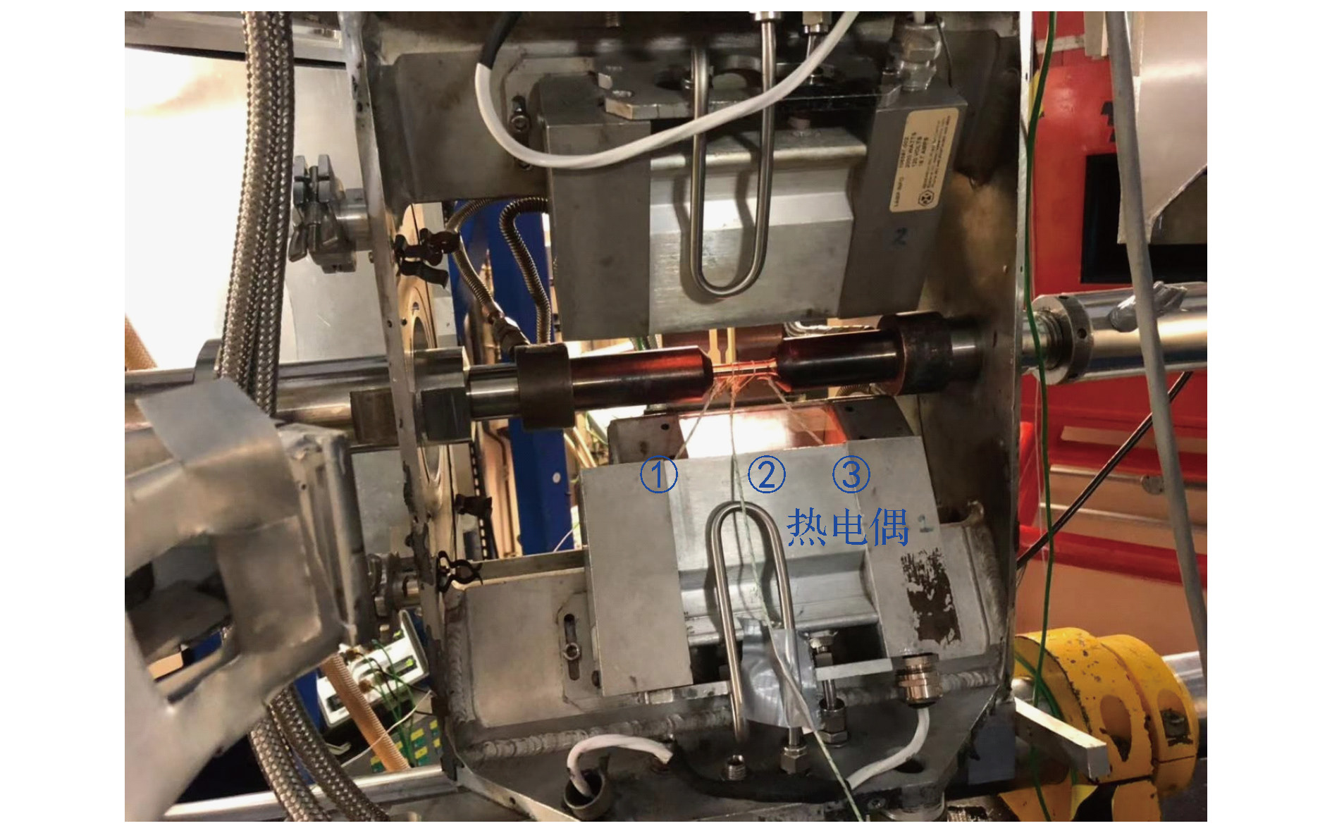 图 9 高温拉伸实验试样加热阶段实物图
Figure9. Sample heating process in high temperature tensile test
 图 10 热模拟中棒状试样在(a) 70%加热功率和(b) 100%加热功率下的温度分布
Figure10. Simulated temperature distribution of screw-threaded sample under (a) 70% heating power and (b) 100% heating power.
