Fund Project:Project supported by the Nuclear Development Research Projects, China (Grant No. kegongersi2017-1341).
Received Date:22 January 2019
Accepted Date:18 March 2019
Available Online:01 June 2019
Published Online:20 June 2019
Abstract:The high-frequency resonant cavity is affected by factors such as beam load, gravity and heat loss caused by cavity deformation during the actual operation of the medical cyclotron. The resonant frequency will shift to a certain extent, resulting in the high-frequency operation frequency varying with the resonant frequency of the resonator cavity. In order to meet the requirements for isochronous acceleration, the magnetic field strength should also be changed correspondingly when the high-frequency operation frequency changes, that is, the magnitude of the magnet current needs changing accordingly, so that the particle cyclotron frequency matches the high-frequency resonant frequency to overcome the sliding phase. Firstly, the static magnetic field model is established by finite element simulation software to simulate the average magnetic field of cyclotron under different magnet currents. Then the relationship between the magnetic field and the resonant frequency is theoretically analyzed. Finally, the relationship between the magnet current and the resonant frequency is obtained when the magnet current varies in a small interval. According to the optimal magnet current corresponding to different resonance frequencies, the automatic frequency tracking of magnet current is completed. In the case of ensuring the maximum carbon film beam, the optimal magnet current corresponding to different resonance frequencies is obtained, which makes the theory validated. According to the relationship, the magnet current is automatically adjusted, which overcomes the slip phase and ensures the stable output of the Faraday beam. The method enables the magnet current to be quickly and accurately find and track the cavity frequency, overcomes the slip phase caused by the frequency offset, and completes the stable output of the beam. Keywords:high frequency cavity/ resonant frequency/ frequency tracking/ stable beam output
根据励磁电流得到束流的相移曲线如图8所示, 得到的谐振频率变化曲线如图9所示. 图 8 励磁电流变化导致的相移 Figure8. Phase shift caused by change of magnet current.
图 9 谐振频率随励磁电流变化量的变化 Figure9. Relation between resonant frequency and magnet current.
从图8可以看出, 励磁电流增加0.5 A, 相移度数增大了37.8985°, 那么励磁电流增加0.01 A, 相移度数增大0.7580°; 励磁电流减少0.01 A, 相移度数减小0.7580°. 从图9可以看出, 励磁电流增加0.5 A, 谐振频率增加了76.429 kHz, 那么谐振频率每增大1.529 kHz, 励磁电流需要增大0.01 A; 谐振频率每减少1.529 kHz, 励磁电流需要减小0.01 A.
4.实验结果在高频功率源启动的初始阶段, 占空比提升, 谐振频率减小, 通过手动调节励磁电流, 以期得到最大碳膜束流. 通过30余次的可靠性打靶实验, 每次在保证最大束流的条件下, 记录不同谐振频率对应的励磁电流, 比较了每次的拟合曲线, 其斜率都是在1.55 kHz附近稍有浮动, 选取其中的一条实验结果, 得到的关系曲线如图10所示. 图 10 谐振频率与励磁电流的对应关系 Figure10. Corresponding relation between resonant frequency and magnet current.
此前, 为了保证靶上束流的稳定性, 通过手动调节磁场大小. 整个打靶过程中, 虽然励磁电流的变化范围约只有0.3 A, 但是对束流的影响是巨大的, 如果不去调节, 可能只产生极小的束流, 甚至可能无法产生束流; 即使励磁电流的变化范围是0.02 A, 束流也会降低约10%; 而且在束流调节过程中, 经常性的调大或调小, 导致束流不够稳定. 基于此, 为了保证束流的足够稳定, 理论分析了励磁电流与谐振频率的关系, 设计了稳定靶流下关于励磁电流与谐振频率的实验, 并设计了励磁电流跟踪谐振频率变化的稳流算法, 在连续2 h的打靶实验中, 得到了如图11所示的靶流变化曲线. 图 11 靶流随时间的变化 Figure11. Variation of target beam current with time.


 图 1 高频相位随时间的变化
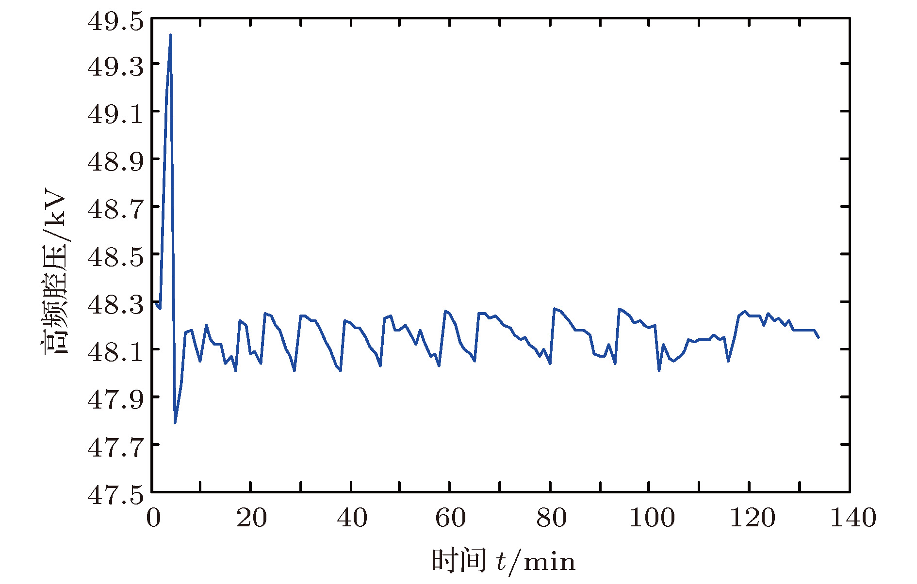 图 2 高频腔压随时间的变化
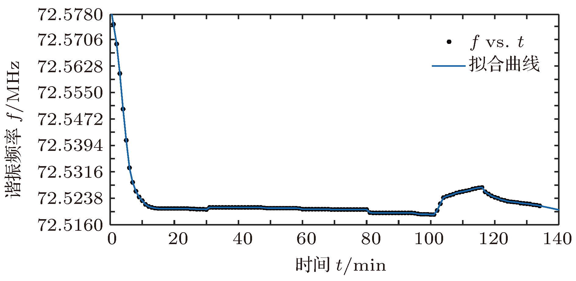 图 3 谐振频率随时间的变化

 图 4 静磁场模型


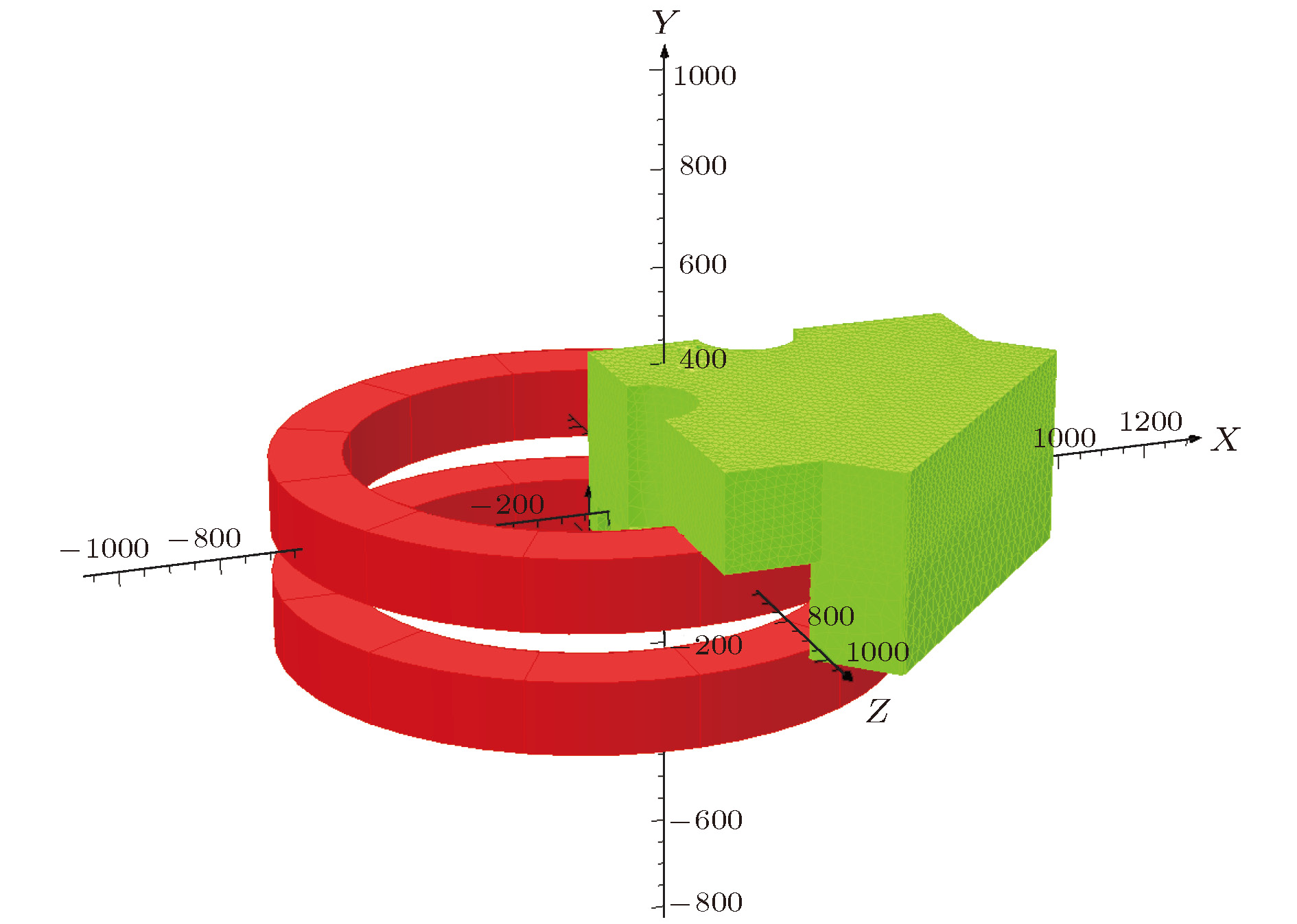 图 5 后处理模型
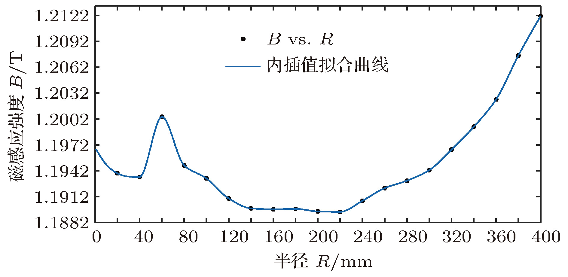 图 6 不同半径的平均磁场变化曲线
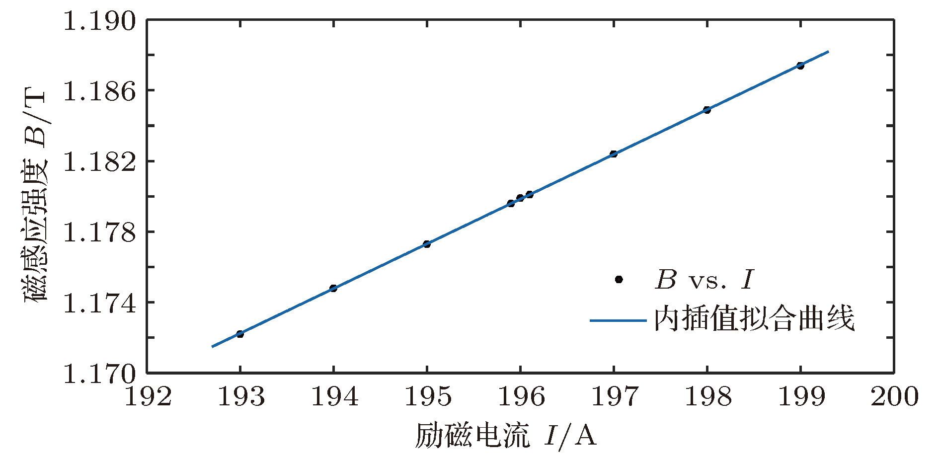 图 7 励磁电流与磁感应强度的关系

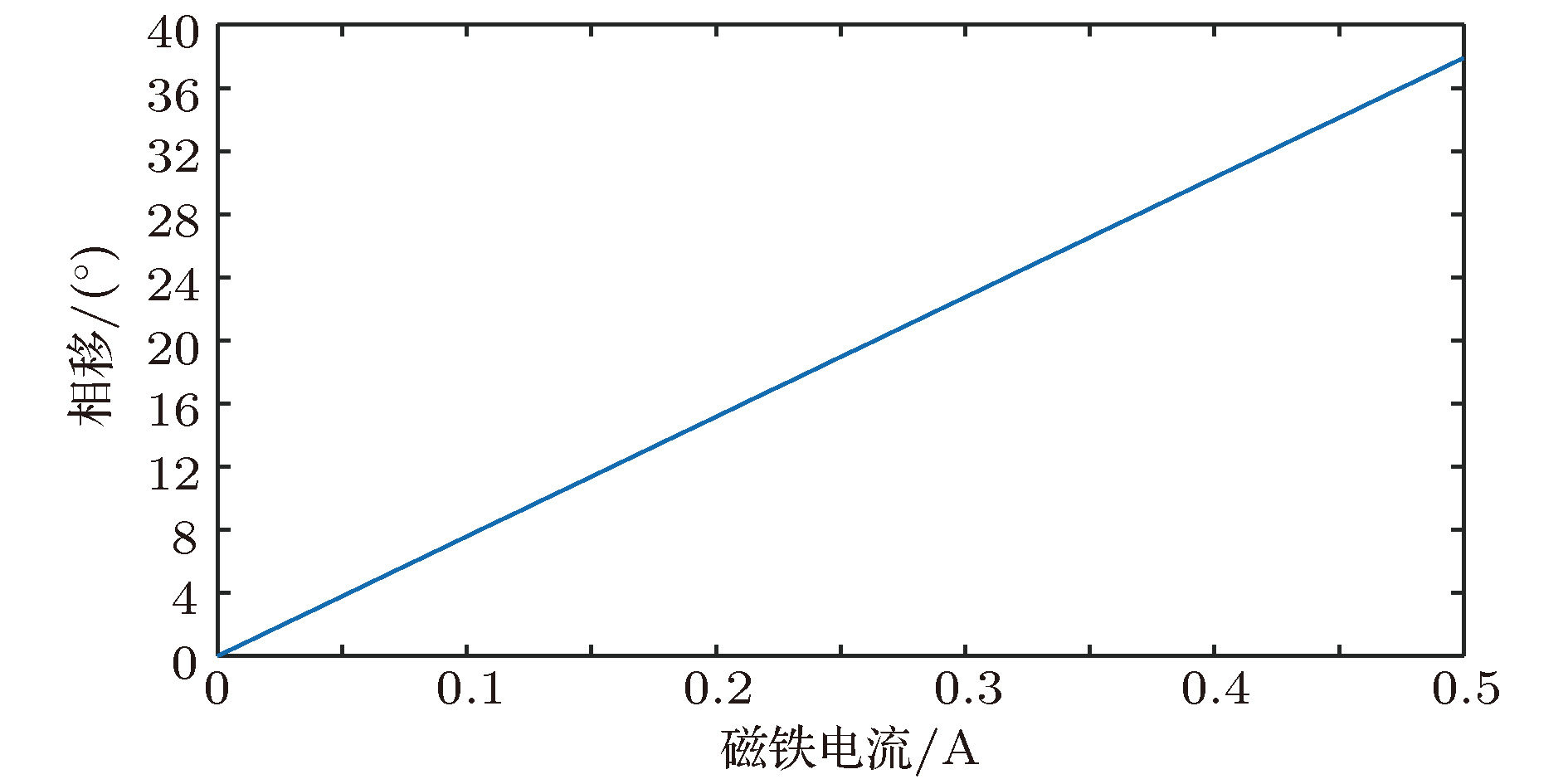 图 8 励磁电流变化导致的相移
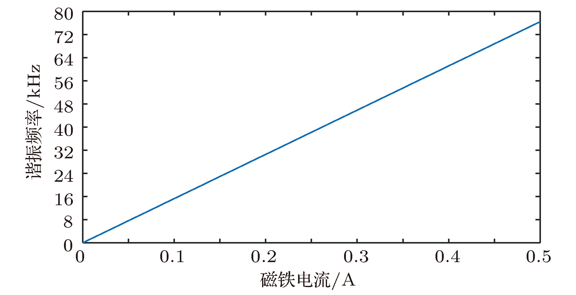 图 9 谐振频率随励磁电流变化量的变化
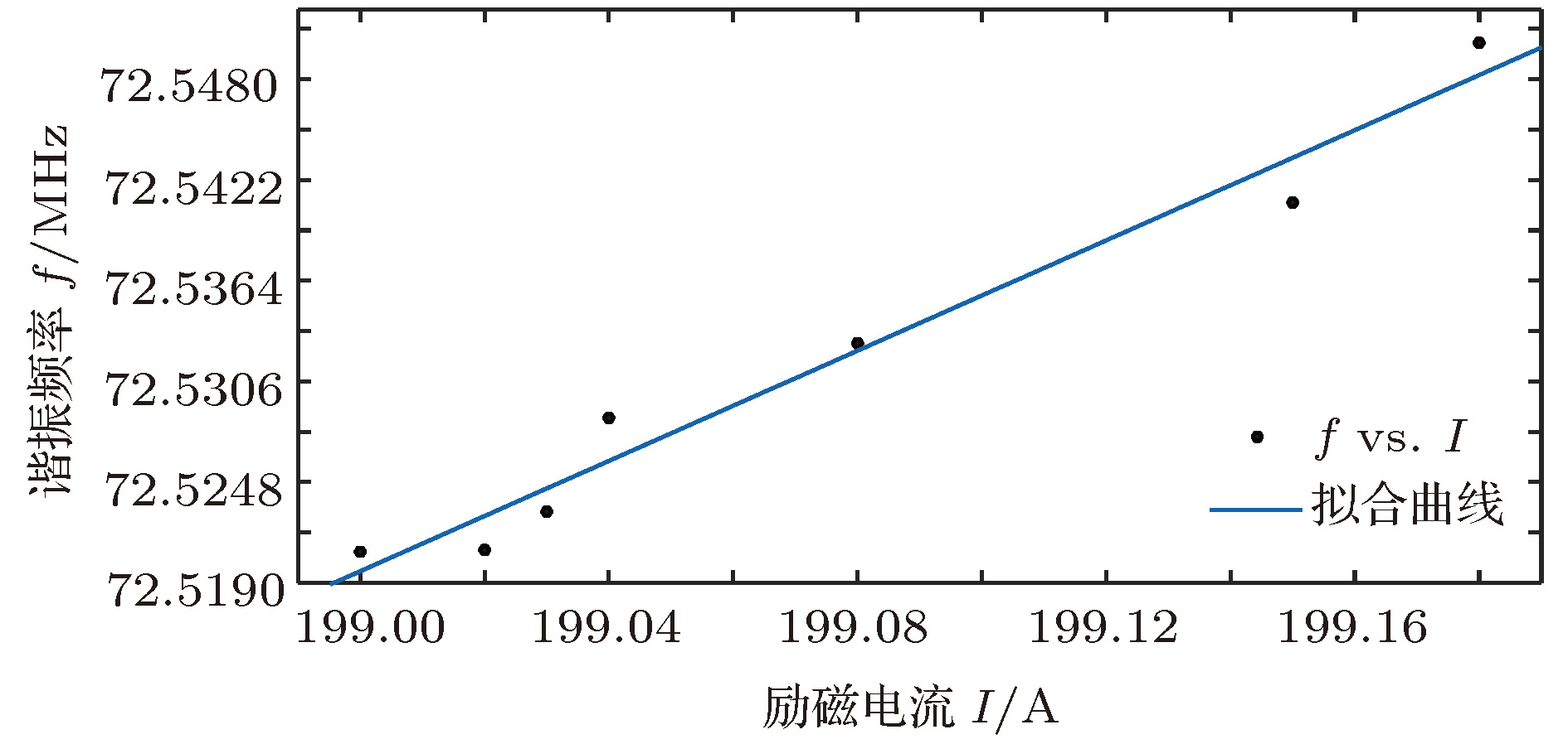 图 10 谐振频率与励磁电流的对应关系
 图 11 靶流随时间的变化
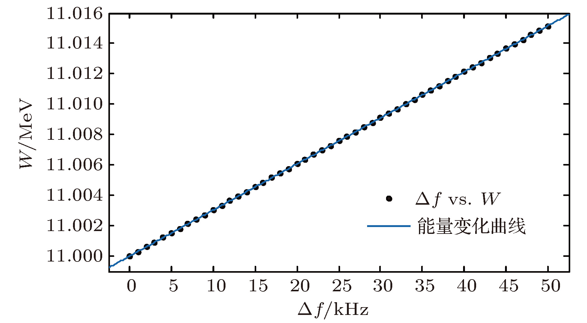 图 12 输出能量的变化情况