1.Department of Physics and Mechanical and Electrical Engineering, Hubei University of Education, Wuhan 430205, China 2.College of Physical Science and Technology, Central China Normal University, Wuhan 430079, China
Fund Project:Project supported by the National Natural Science Foundation of China (Grant No. 11504100).
Received Date:21 July 2018
Accepted Date:28 September 2018
Available Online:01 January 2019
Published Online:20 January 2019
Abstract:Optical diode is a device that can realize unidirectional transmission of light. Its function is similar to that of an electronic diode. It has important applications in the field of optoelectronic integration and all-optical communications. Unidirectional wave transmission requires either time-reversal or spatial inversion symmetry breaking. The magneto-optical effect and optical nonlinearity are usually utilized to break the time-reversal symmetry and obtain the unidirectional transmission. However, these schemes all need high light intensity or magnetic field strength to be realized, and limit the usage. Therefore, spatial inversion symmetry breaking is highly desirable because of totally linear materials under low intensities. Quit a lot of researchers have designed optical diodes based on the photonic crystals and achieved unidirectional transmission for TE-like or TM-like light. The early design realized light unidirectional transmission by PC structures for only one polarization state (TE-like or TM-like incident light). It limits the application for the high integration and reconfigurable optical interconnection. The structure which can achieve unidirectional transmission for both TE and TM polarizations needs to be designed. The annular PCs have been verified to realize polarization-independent phenomena, such as beam splitting, self collimation and waveguide. In this paper, an annular PC is proposed. The plane wave expansion method is used to calculate band structures. The results show that it exhibits a significant directional band gap for both TE and TM mode. Then, the triangular annular PC is constructed, and its transmission spectra and field distributions are calculated by the finite-different time-domain method. It is found that the structure can realize the polarization-independent unidirectional transmission, but the forward transmissivity is too low (about 20%). Moreover, another smaller size annular PC is further introduced to form annular PC heterojunction, which effectively improves the polarization-independent unidirectional transmission performance and the forward transmissivity has doubled. Through the adjustment of the interface structure, the forward transmissivity is further increased. The optimized annular PC heterostructure can realize polarization-independent unidirectional transmission, and the forward transmissivity reaches 44%. The heterostructure can be used to fabricate polarization-independent optical diode, and may have potential applications in complex all-optical integrated circuits. Keywords:annular photonic crystal/ unidirectional transmission/ polarization-independent
图 2 环形孔光子晶体的能带结构 Figure2. Band structure of annular PC.
由图2可知, 当频率为0.4$(a/\lambda )$—0.47$(a/\lambda )$时, 类TE模式入射光将被禁止沿Γ—X方向穿过光子晶体, 却能沿Γ—M方向穿过该区域, 光子晶体对TE模式展现了沿Γ—X方向的禁带特性和Γ—M方向的通带特性, 即方向带隙特性. 同时, 当频率为0.41$(a/\lambda )$—0.46$(a/\lambda )$时, 光子晶体对TM模式也显示了方向带隙特性(Γ—X方向的禁带和Γ—M方向的通带特性). 由此可知, 存在一个共有的频率范围(0.41$(a/\lambda )$—0.46$(a/\lambda )$), 光子晶体能同时对TE模式和TM模式展现出方向带隙特性, 这正是该结构能实现偏振无关单向传输的必要条件. 因此, 基于该环形孔光子晶体结构有望实现光的偏振无关单向传输. 将图1所示环形孔光子晶体沿对角线分割得到如图3(a)所示的三角形状的环形孔光子晶体结构. 利用时域有限差分法计算了该三角形状的环形孔光子晶体的透过谱和场分布图. 整个结构包裹在理想匹配层(PML)吸收边界条件下, 所使用的光源分别为类TE模式高斯波形电磁波和类TM模式高斯波形电磁波. 在结构的输入端设置光源, 并在输出端设置探测器, 探测器的尺寸几乎覆盖整个输出端, 以便有效地记录能流强度随时间演化的数据, 再通过傅里叶变换为频率强度谱, 以光源的频率强度谱作为归一就可以得到结构在不同频率上的透过率[18,22]. 本文不仅要实现偏振无关单向传输特性, 而且特别关注透过率的取值, 希望实现高效的偏振无关单向传输, 因此为了更清晰易读, 本文的透过率均采用线性值表示. 考虑到当光水平(沿$x$轴)入射时, 结构的单向传输性能最佳[23], 因此定义沿$ + x$方向的入射光为正向光, 沿$ - x$方向的入射光为反向光, 当入射光源分别为类TE或类TM模式时, 正、反向透过谱如图3(b), (c)所示. 图 3 (a) 三角形状的环形孔光子晶体; (b)入射光源为类TE模式时的正、反向透过谱; (c) 入射光源为类TM模式时的正、反向透过谱 Figure3. (a) Triangular annular PC structure; (b) the forward and backward transmission spectra of the TE-like incident light; (c) the forward and backward transmission spectra of the TM-like incident light.
图3(b)和图3(c)分别为入射光为类TE模式和类TM模式时三角形状的环形孔光子晶体的透过谱. 由图可知, 当频率为0.41$(a/\lambda )$—0.463$(a/\lambda )$, 该结构对类TE模式的入射光展现出单向传输的特性; 对类TM模式的入射光, 单向传输特性出现在频率0.41$(a/\lambda )$—0.46$(a/\lambda )$内. 由此可知, 0.41$(a/\lambda )$—0.46$(a/\lambda )$为类TE及类TM模式入射光共有的单向传输频率范围, 此结果与能带结构(如图2所示)显示的结果一致. 同时, 当频率为0.419$(a/\lambda )$时, 类TE模式及类TM模式入射光的正向透过率相等, 约为20.9%. 图4给出了频率为0.43$(a/\lambda )$的类TE及类TM模式入射光对应的正、反向场分布图. 由图4可知, 入射光为类TE或类TM模式时, 一部分可沿正向穿透三角形状的环形孔光子晶体, 并从结构的右侧射出, 然而, 绝大部分的入射光被倾斜的交界面反射. 当类TE或类TM模式入射光反向入射时, 由于该频率对应TE模式及TM模式的Γ—X方向禁带, 因此入射光无法沿Γ—X方向穿过PC区域, 在结构的左侧无出射场存在. 场分布图进一步证实了该结构可以实现偏振无关单向传输特性. 图 4 频率为0.43$(a/\lambda )$时, 类TE或类TM模式光入射到三角形状环形孔光子晶体时的正向(a)和(c)、反向(b)和(d)场分布图 Figure4. Forward (a), (c) and backward (b), (d) field distribution of the TE-like or TM-like light at 0.43$(a/\lambda )$ propagating in triangular annular PC.
由以上结果可知, 这种三角形状的环形孔光子晶体能实现偏振无关单向传输, 然而, 该结构的正向透过率太低(约20%), 因此该结构不适合用来构筑高效的偏振无关光二极管. 3.优化设计由第2节的分析可知: 三角形状的环形孔光子晶体可以实现偏振无关单向传输特性, 但是正向传输效率很低(约20%). 为了提高偏振无关单向传输的性能, 本节首先构建环形孔光子晶体异质结结构, 如图5(a)所示. 图5(a)是在图3(a)结构的基础上, 引入另一个较小尺寸的三角形状的环形孔光子晶体构成异质结结构. 结构参数如图5(a)所示, 其中尺寸较小的光子晶体(PC1)的参数为${r_{\rm{i}}} = $$ 0.1a$, ${r_{\rm{o}}} = 0.26a$, 尺寸较大的光子晶体(PC2)的参数仍为${R_{\rm{i}}} = 0.19a$, ${R_{\rm{o}}} = 0.44a$. 图 5 (a)环形孔光子晶体异质结结构;(b) PC1的能带结构;(c)入射光源为类TE模式时的正、反向透过谱; (d)入射光源为类TM模式时的正、反向透过谱 Figure5. (a) Annular PC heterostructure; (b) band structure of PC1; (c) forward and backward transmission spectra of the TE-like incident light; (d) forward and backward transmission spectra of the TM-like incident light.
由第2节分析已获知, 当频率为0.41$(a/\lambda )$—0.46$(a/\lambda )$内, PC2对TE和TM模式同时展现了沿Γ—X方向的禁带和Γ—M方向的通带特性. 采用平面波展开法计算了PC1的能带结构, 结果如图5(b)所示, 当频率约为0.42$(a/\lambda )$—0.46$(a/\lambda )$时, PC1对TE和TM模式同时具有沿Γ—X方向及Γ—M方向的通带特性. 因此, 当频率处在0.42$(a/\lambda )$—0.46$(a/\lambda )$时, PC1对TE及TM模式均为全方向导带, 而PC2对TE及TM模式均存在方向带隙(Γ—X方向的禁带和Γ—M方向的通带), 这正是异质结结构能实现单向传输的必要条件[18,21,22]. 因此, 0.42$(a/\lambda )$—0.46$(a/\lambda )$是环形孔光子晶体异质结对TE模式及TM模式共有的单向传输的频率范围. 图5(c)和图5(d)分别为入射光为类TE和类TM模式时的透过谱. 由图可知, 当入射光为类TE模式时, 单向传输特性出现在频率0.42$(a/\lambda )$—0.47$(a/\lambda )$范围内, 且当频率值为0.434$(a/\lambda )$时最大正向透过率约为53.4%; 当入射光为类TM模式时, 单向传输频率范围为0.41$(a/\lambda )$—0.455$(a/\lambda )$, 最大正向透过率约为49.2% (0.425$(a/\lambda )$), 即: 环形孔光子晶体异质结结构在0.42$(a/\lambda )$—0.455$(a/\lambda )$范围内实现了偏振无关单向传输, 此结果与上述能带结构显示的结果相吻合. 同时, 当频率为0.43$(a/\lambda )$时, 类TE及类TM模式入射光的正向透过率相等, 约为40%. 图6给出了频率为0.43$(a/\lambda )$的类TE及类TM模式入射光对应的正、反向场分布图. 当类TE及类TM模式入射光正向入射时, 因PC1具有Γ—X方向的通带特性, 入射光可穿透PC1到达环形孔光子晶体的异质结界面, 同时此频率位于PC2光子晶体Γ—M方向通带区域, 因此部分光由于折射效应穿过PC2区域并从结构的右侧发射出来; 当类TE模式和类TM模式入射光反向入射时, 因PC2具有Γ—X方向禁带, 入射光不能沿Γ—X方向穿过PC2区域, 因此在PC1的左侧几乎观测不到出射场. 场分布图进一步证实了该结构具有偏振无关单向传输特性. 图 6 频率为0.43$(a/\lambda )$时, 类TE或类TM模式光入射到环形孔光子晶体异质结时的正向(a)和(c)、反向(b和d)场分布图 Figure6. Forward (a), (c) and backward (b), (d) field distribution of the TE-like or TM-like light at 0.43$(a/\lambda )$ propagating in the annular PC heterostructure.
同时, 与三角形状的环形孔光子晶体(图3(a))相比, 该环形孔光子晶体异质结结构具有更好的偏振无关单向传输性能, 正向透过率增大了一倍. 进一步, 将PC2结构中靠近交界面的一组空气环的尺寸减小至内径$0.1a$、外径$0.26a$, 形成如图7(a)所示的结构. 图7(b),(c)为该优化结构对应的入射光为类TE和类TM模式的透过谱,由图可知, 类TE和类TM模式光入射时的透过谱与未优化的环形孔光子晶体异质结的透过谱曲线相似, 在频率约为0.42$(a/\lambda )$—0.455$(a/\lambda )$范围内显示了偏振无关单向传输的特性. 然而, 界面优化后, 正向透过率有所提高, 其中, 类TE模式入射光对应的正向透过率峰值为57.9%(0.435$(a/\lambda )$), 类TM模式入射光对应的正向透过率峰值为55%(0.426$(a/\lambda )$), 并且当频率约为0.43$(a/\lambda )$时, 类TE及类TM模式入射光对应的透过率相等, 约为44%. 图8为频率为0.43$(a/\lambda )$时的场分布图. 场分布图结果证实, 该结构具有偏振无关单向传输特性. 图 7 (a)优化后的环形孔光子晶体异质结结构;(b)入射光源为类TE模式时的正、反向透过谱;(c)入射光源为类TM模式时的正、反向透过谱 Figure7. (a) Optimized annular PC heterostructure; (b) forward and backward transmission spectra of the TE-like incident light; (c) forward and backward transmission spectra of the TM-like incident light.
图 8 频率为0.43$(a/\lambda )$时, 类TE及类TM模式光入射到优化后的环形孔光子晶体异质结时的正向(a)和(c)、反向(b和d)场分布图 Figure8. Forward (a), (c) and backward (b), (d) field distribution of the TE-like and TM-like light at 0.43$(a/\lambda )$ propagating in the optimized annular PC heterostructure.


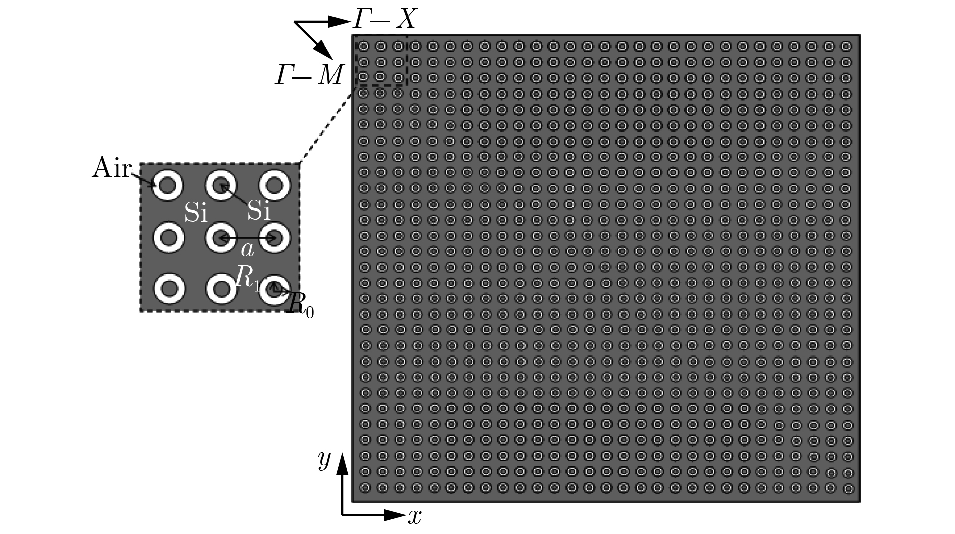 图 1 环形孔光子晶体的结构及参数
 图 2 环形孔光子晶体的能带结构


 图 3 (a) 三角形状的环形孔光子晶体; (b)入射光源为类TE模式时的正、反向透过谱; (c) 入射光源为类TM模式时的正、反向透过谱


 图 4 频率为0.43


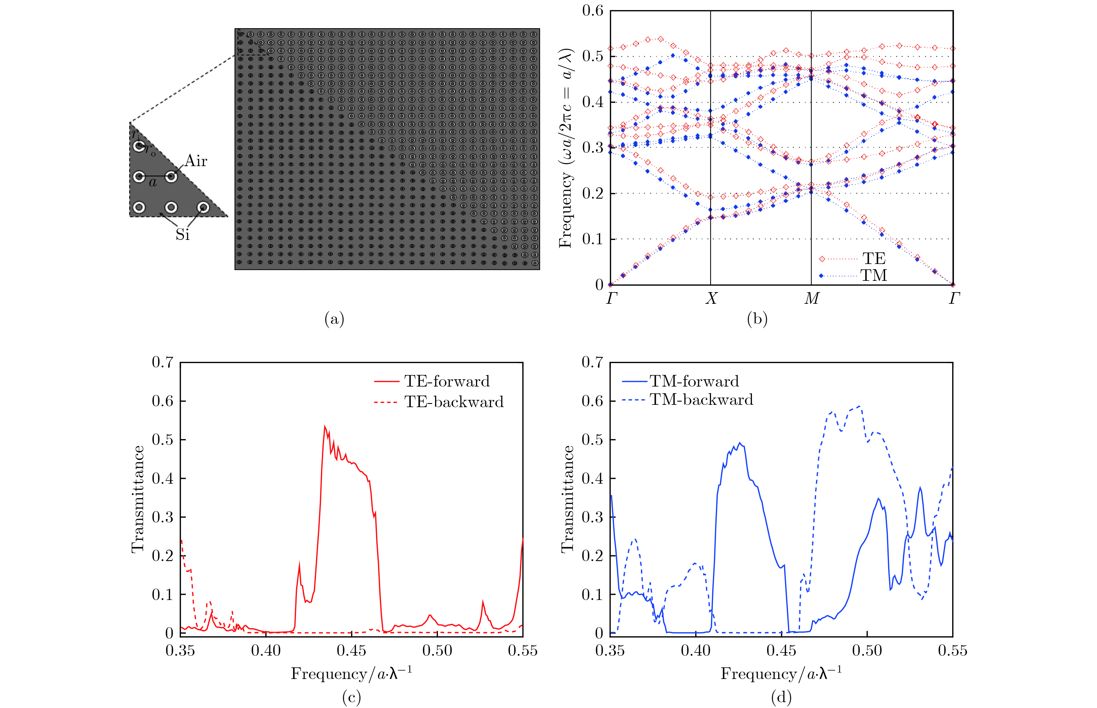 图 5 (a)环形孔光子晶体异质结结构;(b) PC1的能带结构;(c)入射光源为类TE模式时的正、反向透过谱; (d)入射光源为类TM模式时的正、反向透过谱


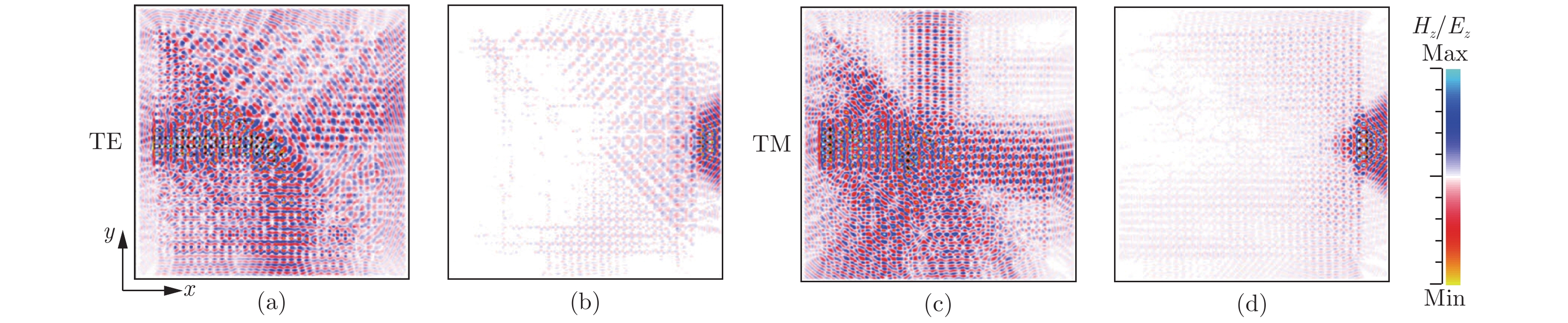 图 6 频率为0.43


 图 7 (a)优化后的环形孔光子晶体异质结结构;(b)入射光源为类TE模式时的正、反向透过谱;(c)入射光源为类TM模式时的正、反向透过谱
 图 8 频率为0.43


