 ,2)华南理工大学亚热带建筑科学国家重点实验室, 广州 510641
ON THE UNIFIED PHASE-FIELD THEORY FOR DAMAGE AND FAILURE IN SOLIDS AND STRUCTURES: THEORETICAL AND NUMERICAL ASPECTS1)
Wu Jianying,2)State Key Laboratory of Subtropical Building Science, South China University of Technology, Guangzhou 510641, China通讯作者: 2) 吴建营, 教授, 主要研究方向: 固体和结构损伤破坏力学. E-mail:jywu@scut.edu.cn
收稿日期:2020-08-20接受日期:2020-09-22网络出版日期:2021-02-07
| 基金资助: |
Received:2020-08-20Accepted:2020-09-22Online:2021-02-07
作者简介 About authors

摘要
固体开裂引起的损伤和断裂是工程材料和结构最为普遍的破坏形式. 为了防止这种破坏, 结构设计首先必须了解裂缝在固体内如何萌生、扩展、分叉、汇聚甚至破碎; 更重要的是, 还需要准确量化这些裂缝演化过程对于结构完整性和安全性降低的不利影响. 针对上述固体结构损伤破坏问题, 本工作系统地介绍了笔者提出的统一相场理论、算法及其应用. 作为一种裂缝正则化变分方法, 统一相场理论将基于强度的裂缝起裂准则、基于能量的裂缝扩展准则以及满足变分原理的裂缝路径判据纳入同一框架内. 不仅常用的脆性断裂相场模型是该理论的特例, 还自然地给出了一类同时适用于脆性断裂和准脆性破坏的相场正则化内聚裂缝模型即 PF-CZM. 该模型非常便于通过有限元等方法加以数值实现; 为了求解有限元空间离散后得到的非线性方程组, 还介绍了几种常用的数值算法, 其中整体BFGS拟牛顿迭代算法的计算效率最高. 静力、动力和多场耦合条件下若干二维和三维代表性算例表明: 相场正则化内聚裂缝模型 PF-CZM能够高精度地再现复杂裂缝演化导致的脆性和准脆性固体损伤破坏; 特别是, 所有情况下, 模型的数值结果不依赖于裂缝尺度参数和有限元网格. 因此, 该模型具有相当好的预测能力, 有望在工程结构的损伤破坏分析方面发挥重要作用. 最后建议了若干值得进一步开展的研究课题.
关键词:
Abstract
Cracking-induced damage and fracture are the most commonly encountered failure modes of engineering materials and structures. In order to prevent such failure, it is a prerequisite in structural designs to understand how cracks nucleate, propagate, branch, coalesces and even fragmentation, etc., in solids, and more importantly, to quantify their adverse effects to the loss of integrity and even catastrophic collapse of structures. Aiming to provide a feasible approach in the modeling of damage and quasi-brittle failure in solids, this work presents systematically the theoretical and numerical aspects of the unified phase-field theory proposed recently by the author, with applications to a couple of representative benchmark problems. Being a variational approach for regularized cracks, this theory incorporates intrinsically the strength-based nucleation and energy-based propagation criteria, as well as the energy minimization-oriented path following criterion, in a standalone framework. Not only several popular phase-field models for brittle fracture can be recovered as particular examples, but also a novel model——the phase-field regularized cohesive zone model (or shortly, PF-CZM)——that applies to both brittle fracture and quasi-brittle failure, emerges naturally. This model can be numerically implemented in context of the coupled finite element method. In order to solve efficiently the discretized governing equations, several numerical algorithms are discussed, with the monolithic BFGS quasi-newton method being the most efficient one. Representative two- and three-dimensional numerical examples reveal that the PF-CZM is capable of reproducing complex fracture configurations in both brittle and quasi-brittle solids under quasi-static, dynamic and multi-physical environments. Remarkably, in all cases objective numerical predictions are achieved independent of the incorporated length scale and mesh discretization. Therefore, the PF-CZM can be used as a numerically predictive approach for the modeling of damage and failure in engineering structures. Finally, some research topics deserving further studies are suggested.
Keywords:
PDF (6488KB)元数据多维度评价相关文章导出EndNote|Ris|Bibtex收藏本文
本文引用格式
吴建营. 固体结构损伤破坏统一相场理论、算法和应用1). 力学学报[J], 2021, 53(2): 301-329 DOI:10.6052/0459-1879-20-295
Wu Jianying.
引言
自1920年Griffith[1]创立线弹性断裂力学一个世纪以来, 工程材料和结构的损伤破坏问题一直是国际固体力学领域方兴未艾的研究热点和难点. 一方面, 伴随着研究人员在应力强度因子[2]、内聚裂缝模型[3-5]、J积分[6]等方面取得的重要进展, 断裂力学理论渐趋成熟[7]. 另一方面, Kachanov[8]于1958年提出了金属高温蠕变的损伤模型, 直至20世纪80年代引入裂缝带理论[9]处理含应变软化段的本构关系, 损伤力学理论也获得了长足发展[10-11]. 将断裂力学理论或损伤力学理论与有限元等数值方法相结合, 研究人员分别发展了损伤破坏分析的非连续方法[12]或连续方法[13], 损伤与破坏力学逐渐演变为固体力学的重要分支, 并在工程结构安全分析和优化设计等方面发挥了重要作用[14-15].然而, 无论是断裂力学或损伤力学理论, 还是相应的非连续或连续数值方法, 均存在一系列长期难以解决的难题. 断裂力学理论自身缺乏裂缝起裂和分叉准则, 研究人员对最大环向应力、最大能量释放率、最大应变能密度等裂缝扩展方向判据的认识也有明显分歧; 数值上, 直接处理位移跳跃的非连续方法需要繁琐的网格重划分(对于界面单元)或复杂的裂缝几何表征、裂缝路径跟踪等(对于扩展有限元、内嵌裂缝方法等)[16]. 损伤力学模型可以自动处理裂缝起裂、扩展和分叉等复杂行为, 但损伤变量缺乏明确的物理意义, 与裂缝之间也不存在一一对应关系, 故而难以准确预测裂缝位置、裂缝宽度等工程中极为关心的局部信息; 将含应变软化段的经典损伤力学模型应用于结构损伤破坏的数值分析时, 会遭遇网格敏感性、应力锁死等难题[17]; 即便是非局部损伤模型(无论积分型或微分型), 也存在材料内部尺度随意选取、边界效应处理困难、裂缝带无限变宽等众多缺点[18]. 事实上, 正如2009年底美国三院院士Ba?ant[19]在铁木辛柯奖章颁奖礼上的致辞中指出: "固体和结构的损伤破坏问题, 与流体力学中的湍流, 并称为21世纪工程科学的两大难题"; 20世纪90年代中期, 中国科学院院士杨卫[20]也有类似的表述.
20世纪末、21世纪初, 研究人员提出了两类新的固体损伤破坏分析方法, 即近场动力学[21]和相场断裂模型[22-23]. 近场动力学方法引入非局部微分算子, 将固体力学中的变形协调和力平衡偏微分方程改写为积分方程, 无需对固体损伤破坏时的不连续位移场进行特别考虑, 能够处理裂缝起裂、扩展、分叉等问题[24-26]. 然而, 该方法难以与经典材料本构关系直接对应[27]、存在波色散[28]和零能模式[29]等缺点, 在数值上也与有限元方法不兼容, 因此这里不做进一步讨论.
相场断裂模型根植于Francfort和Marigo[22]提出的线弹性断裂能量变分原理, 即实际裂缝路径使得固体系统的总能量最小, 完美地解决了Griffith能量方法需要预设裂缝路径的难题[30]. 在理论上, 该模型借鉴了计算机图像分割中Mumford-Shah泛函[31]的椭圆型正则化方法[32](因此, 该模型也被称为AT2相场模型[33]), 将尖锐裂缝正则化为具有一定尺度的裂缝带, 并引入在[0, 1]范围内连续分布的裂缝相场变量及其梯度描述裂缝状态. 由能量变分原理给出的裂缝相场控制方程在形式上与凝聚态物理中的Ginzberg-Landau相变方程[34]、多相流体力学中的Allen-Cahn扩散界面方程[35]以及计算机图像分割中的Ambrosio-Tortorelli方程[32]均有异曲同工之处. 在数值上, 该模型可以非常方便地通过有限元、无网格、物质点甚至近场动力学等多种数值方法加以实现. 可以严格证明[36]: 当裂缝尺度趋近于零时, 上述相场断裂模型$\varGamma$ -收敛于Griffith线弹性断裂力学. 2010年以来, 德国的Miehe等[37-38]引入经典损伤力学中的能量拉-压分解[39]、历史最大损伤能释放率[40]等概念, 在热力学理论框架内重新推导了上述脆性断裂相场模型, 并将其应用于固体结构的静力、动态和多场耦合破坏分析. 至此以后, 相场断裂模型迅速得到了学术界的广泛重视, 研究人员开展了大量的跟踪研究和应用工作. 例如, 法国的Marigo团队[41]提出了脆性断裂相场模型AT1, 解决了AT2模型缺乏线弹性段的问题; 在国内, 近年来清华大学庄茁团队[42-44]将相场断裂模型AT2应用于动态热-力耦合条件下的绝热剪切带分析, 中国科学技术大学李良彬团队[45-46]采用AT2模型开展了高速冲击下脆性和超弹性材料的动态破坏分析.
令人遗憾的是, 上述相场断裂模型AT1/2均仅适用于脆性破坏, 无法应用于工程中普遍存在的准脆性材料和结构. 更糟糕的是, 模型的分析结果存在严重的裂缝尺度敏感性问题: 裂缝尺度越小, 结构的极限承载力(峰值载荷)越大. 因此, 若将裂缝尺度视为数值参数以保证模型的$\varGamma$ -收敛特性, 则此类模型与Griffith线弹性断裂力学类似, 同样无法描述完好或仅有弱奇异性固体的裂缝起裂. 迫不得已, 研究人员只好放弃相场断裂模型的$\varGamma$ -收敛性质, 并类似非局部损伤模型[47-48], 将裂缝尺度视为材料属性[33]. 然而, 最新研究表明: 上述处理方法仍然无法完全解决裂缝起裂问题[49], 这一致命缺陷也被相场断裂模型的创建者所证实[50].
为了解决上述问题, 荷兰的de Borst团队[51-53]以及意大利的Iurlano团队[54-55]等分别尝试从内聚裂缝模型出发建立相场模型. 然而, 前者仅适用于界面裂缝而无法考虑任意裂缝扩展路径, 后者则同样存在裂缝尺度敏感性问题.
2017年以来, 笔者将断裂力学和损伤力学有机结合, 引入两个参数化的特征函数即裂缝几何函数和能量退化函数, 分别表征固体破坏时的裂缝相场分布特征以及开裂固体应变能的退化规律, 基于热力学基本原理建立了同时适用于脆性断裂和准脆性破坏的统一相场理论[56]. 从该理论出发, 不仅脆性断裂相场模型AT1/2可以作为其特例直接给出, 还在国际上首次提出了一类相场正则化内聚裂缝模型PF-CZM[57-58]. 理论分析证明: 当裂缝尺度趋近于零时, 该模型收敛为一类混合型破坏的内聚裂缝模型[59-60], 能够准确预测线性软化以及指数软化、双曲型软化、混凝土科内列森软化[61]等常用的非线性软化曲线. 由于同时考虑了基于强度的裂缝起裂准则、基于能量的裂缝扩展准则以及基于变分原理的裂缝扩展方向判据, 该模型仅需少量标准材料参数即可定量预测工程结构的损伤破坏行为; 特别是, 当裂缝尺度小于某一上限时, 其取值对脆性断裂和准脆性破坏的分析结果几乎不产生影响. 归功于上述优点, 统一相场理论提出后迅速得到了国内外****的广泛认可和跟踪研究, 并被成功应用于静力、动力和多场耦合条件下混凝土[62]、岩石[63]、冰[64]、玻璃[65]、PMMA[58]、复合材料[66-67]、橡胶[68-69]等多种固体材料和结构的损伤破坏分析.
前已述及, 相场模型可以非常方便地通过多种常用数值方法加以实现. 然而, 由于裂缝相场梯度的引入, 为保证计算结果的数值精度, 裂缝带附近的空间离散必须具有足够的数值分辨率, 往往导致系统总自由度数目较大, 对非线性方程数值求解算法提出了很高要求. 已有研究大多遵循文献[23, 30]的建议, 采用裂缝相场-位移场交错迭代求解器. 该求解器具有优异的数值健壮性, 但收敛速度极慢(对于某些裂缝快速扩展的关键步, 往往需要成百甚至上千次全局迭代才能收敛). 因此, 已有固体结构损伤破坏的相场分析往往局限于简单二维算例, 复杂三维问题的相场模拟极为少见[70]. 近年来, 笔者采用整体隐式BFGS拟牛顿迭代算法求解裂缝相场-位移场耦合方程, 计算效率较交错迭代求解器大幅度提升[71-73], 成功地在个人计算机上开展了复杂三维问题的相场分析[74]. 结合并行计算技术和大型超算平台, 有望应用于实际工程结构的损伤破坏分析.
考虑到统一相场理论的相关研究工作分散发表于若干外文期刊, 本工作将对该理论及其数值算法和应用算例加以系统总结、整理和介绍, 以期为工程结构的损伤破坏分析提供一种可行的方法, 并对该方向今后的研究工作进行展望.
1 统一相场理论
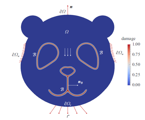
不失一般性, 考虑如图1所示内嵌裂缝/界面的固体$\varOmega \subset { R}^{n_{\dim}}$ ($n_{\dim} = 1, 2, 3$), 其外边界和外法向矢量分别记为$\partial \varOmega \subset { R}^{n_{\dim} - 1}$和$\boldsymbol{n}$. 虽然统一相场理论同样适用于有限变形[75], 这里仅考虑小应变情况, 故采用位移场$\boldsymbol{u} (\boldsymbol{x})$和线性应变场$\epsilon (\boldsymbol{x}) := \nabla^{{\rm s}} \boldsymbol{u} (\boldsymbol{x})$描述固体的变形状态, 这里$\boldsymbol{x}$为空间坐标, $\nabla^{{\rm s}} (\cdot)$表示对称梯度算子. 为保证边值问题的适定性, 外边界$\partial \varOmega$分成互补的两部分$\partial \varOmega_{u}$和$\partial \varOmega_{\rm t}$, 并分别施加给定的位移边界$\boldsymbol{u}^{\ast} (\boldsymbol{x})$和力边界$\boldsymbol{t}^{\ast} (\boldsymbol{x})$.图1
 新窗口打开|下载原图ZIP|生成PPT
图1固体内嵌裂缝/界面及其几何正则化[60]
Fig.1A cracking solid and its geometric regularization[60]
1.1 裂缝/界面的相场正则化
相场模型将如图1所示的尖锐裂缝/界面$\mathcal{S}$弥散为有限尺度$b > 0$的裂缝带$\mathcal{B} \subseteq \varOmega$, 并引入裂缝相场$d (\boldsymbol{x}) : \mathcal{B} \to [0, 1]$描述其状态; 裂缝带$\mathcal{B}$的外边界记为$\partial \mathcal{B}$, 其外法向矢量表示为$\boldsymbol{n}_{\mathcal{B}}$. 需要指出的是, 在固体损伤破坏过程中裂缝带$\mathcal{B}$并非预先设定或保持固定, 而是遵循自身特定的本构行为进行扩展、演化. 类似于位移场, 裂缝相场也可以施加某种强迫边界条件. 例如, 对于弹性区域有$d (\boldsymbol{x}) = 0$; 对于预制的初始裂缝有$d (\boldsymbol{x}) = 1$等.根据图像分割理论[36], 裂缝面积$A_{\mathcal{S}}$可以表示为如下体积分[37]
式(1)中, 左侧第一个大括号代表尖锐裂缝, 右侧大括号代表正则化裂缝. 意大利数学家Ambrosio和Tortorelli[32]在对图像分割Mumford-Shah泛函[31]进行正则化时, 最早给出了形如式(2)的裂缝面积密度泛函, 其裂缝几何函数取为$\alpha (d) = d^{2}$. 可以严格证明[36]: 当裂缝尺度$b$趋近于零时, 式(1)给出的裂缝面积$A_{\mathcal{S}}$满足$\varGamma$ -收敛即$A_{\mathcal{S}} = \lim_{b \to 0} A_{d} (d)$. 裂缝面积密度$\gamma (d; \nabla d)$是裂缝相场$d$及其梯度$\nabla d$的如下函数
式中$b > 0$为裂缝尺度, 裂缝几何函数$\alpha (d) \in [0, 1]$是裂缝相场$d (\boldsymbol{x})$的递增函数, 并满足如下条件[56]
为了保证固体破坏时局部能量耗散的递增性质, 这里引入了条件(3)$_{1}$ (公式号的下标$1$代表公式中的第$1$式; 以此类推), 在物理学领域, 美国Karma教授团队最早采用双势阱函数$\alpha (d) = d^{2} \big(1 - d \big)^{2}$并基于Ginzberg-Landau相变方程[34]建立脆性断裂相场模型[76-77]. 双势阱函数满足性质$\alpha (0) = \alpha (1) = 0$, 即材料处于中间过渡状态时的势函数比纯相时更大, 这一特点与材料相变、多相流或结构拓扑优化等问题[78]较为契合. 虽然双势阱函数同样满足$\varGamma$ -收敛特性, 但该函数在$[0, 1]$之间不具有单调递增性, 也无法区分$d = 0$和$d = 1$这两种截然不同的裂缝状态. 因此, 若将其作为裂缝几何函数, 将会导致裂缝面积和能量耗散随裂缝扩展先增大后降低, 这与固体断裂时Griffith能量原理(即应变能减小、裂缝表面能增大、最终总能量达到最小值)相矛盾. 本文仅讨论满足条件(3)的裂缝几何函数.
受裂缝影响, 固体Helmholtz自由能$\psi$发生退化, 并表示为如下一般形式
表征裂缝相场影响的能量退化函数$\omega (d) \in [0, 1]$应满足以下条件[37]
特别指出, 条件(5)$_{4}$保证固体损伤破坏过程中裂缝带的宽度不会持续增大.
1.2 裂缝相场演化的能量原理
热力学第一定律和第二定律要求: 等温绝热条件下, 任意容许的变形过程必须满足如下能量耗散不等式式中, 应力张量$\sigma$与应变张量$\epsilon$功共轭; $\dot{( \; )}$为时间导数. 代入Helmholtz自由能函数(4), 并考虑应变率$\dot{\epsilon}$的任意性, 可以给出固体的应力-应变关系并定义裂缝相场的能量释放率
其中, $\bar{Y} := \partial \psi / \partial \omega$为有效能量释放率, $\omega' (d) := \partial \omega / \partial d$为能量退化函数的导数. 相应的, 能量耗散不等式(6)简化为
式(8)表征了固体损伤破坏过程中的应变能释放.
由此, 可以给出如下裂缝相场演化的能量原理[56-57].
(1) 裂缝相场演化的不可逆性: 在封闭系统中, 裂缝相场演化满足不可逆性, 即
因此, 裂缝相场的变分$\delta d \geqslant 0$非负(这里不考虑裂缝愈合).
(2) 裂缝相场演化的能量准则: 裂缝相场的准静态演化满足如下关系式
$\begin{align*} \delta\mathscr{D} = \underbrace{\int_{\mathcal{B}} Y \delta d \; {\rm d}V} \leqslant \underbrace{G_{{\rm f}} \; \delta A_{\mathcal{S}} = \int_{\mathcal{B}} G_{{\rm f}} \; \delta \gamma \; {\rm d}V} \end{align*}$
式中, $G_{{\rm f}}$为固体的断裂能常数, 第一个大括号代表应变能释放, 第二个大括号代表裂缝表面能.
利用高斯-斯托克斯散度定理并根据裂缝相场变分的非负特性$\delta d \geqslant 0$, 可以给出如下裂缝相场演化的能量准则
裂缝面积密度函数$\gamma$的变分导数$\delta_{d} \gamma$表示为
式中, $\Delta d = \nabla \cdot \nabla d$为裂缝相场的拉普拉斯运算符; $\alpha' (d) := \partial \alpha / \partial d$为裂缝几何函数的导数. 此外, 还有如下边界条件
其中, 通量$\boldsymbol{q}$与裂缝相场梯度$\nabla d$之间满足线性本构关系, 比例系数与裂缝尺度$b > 0$成正比.
(3) 裂缝相场演化的能量守恒: 任意时刻, 裂缝相场演化还需要满足能量守恒原理, 即
当$g (Y, d) < 0$时, 裂缝相场发生卸载即$\dot{d} = 0$; 当裂缝相场发生进一步演化即$\dot{d} > 0$时, 必须满足能量准则$g (Y, d) = 0$和边界条件$\boldsymbol{q} \cdot \boldsymbol{n}_{\mathcal{B}} = 0$.
式(9)、式(10)和式(13)可以统一写成
上述裂缝相场演化的能量原理将断裂力学和经典损伤力学紧密联系, 构建了两种理论之间的桥梁.
1.3 裂缝相场-位移场控制方程
可以将裂缝相场演化能量准则(10)和边界条件(12)改写为如下形式即裂缝相场通量$\boldsymbol{q}$的散度与相场源$Q (\epsilon, d)$平衡
同时, 位移场$\boldsymbol{u}$应满足经典的力平衡方程
式中, $\boldsymbol{b}^{\ast}$为体积均布力.
可以看出, 上述偏微分方程在形式上一致且相互耦合, 构成了统一相场理论的裂缝相场-位移场耦合控制方程.
可以证明[59,79], 上述裂缝相场-位移场耦合控制方程与系统总能量最小原理[23,30]等效, 即
其中, 系统总能量$\mathcal{E}$表示为
式中, 第一、二、三个大括号分别代表固体应变能、裂缝表面能、系统总势能. 换句话说, 在所有可能的裂缝路径中, 实际裂缝使得系统总能量最小. 与经典Griffith能量理论不同的是, 这里不要求预设或已知裂缝路径.
统一相场理论同样适用于固体结构的动态损伤破坏分析. 此时, 平衡方程(15c)$_{1}$需考虑惯性力的影响, 即[59,80]
式中, $\rho$为材料密度, $\ddot{\boldsymbol{u}} = {\rm d}^{2} \boldsymbol{u} / {\rm d}t^{2}$为加速度. 对于动载荷作用时间较长的结构动力响应分析, 往往还需要进一步考虑结构阻尼; 此外, 如果需要直接描述材料的应变率效应, 可以通过引入微惯性和微阻尼对裂缝相场演化方程的影响, 详见文献[59, 81].
1.4 应力-应变本构关系
控制方程(15)还需补充Helmholtz自由能$\psi$的具体表达式. 显然, 其定义与分析对象和分析目的直接相关. 特别是, 对于脆性和准脆性固体, 与Helmholtz自由能对应的应力-应变本构关系和裂缝相场能量释放率(7)必须考虑材料受拉-受压力学行为的不同特性. 为此, 类似于损伤力学的思路[39,82], 研究人员分别提出了应变球-偏分解[83-84]、应变拉-压谱分解[38]、有效应力拉-压能量正交分解[60,85]等多种方法, 对材料Helmholtz自由能$\psi$进行分解, 详见综述[59]中的讨论.为简单起见, 这里采用各向同性Helmholtz自由能定义
有效应力张量$\bar{\sigma}$由如下线弹性关系给出
式中, ${ E}_{0}$和${ C}_{0}$分别为材料的弹性刚度张量和柔度张量. 于是, 由式(7)得到
有效能量释放率$\bar{Y}$表示为
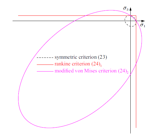
其中, $E_{0}$和$\nu_{0}$分别为材料杨氏模量和泊松比. 如图2所示, 上述应力-应变本构关系将给出完全对称的受拉和受压力学行为, 这与脆性和准脆性材料的实际力学特性不符.
图2
 新窗口打开|下载原图ZIP|生成PPT
图2不同有效能量释放率定义给出的强度包络线: 平面应力状态
Fig.2Strength envelopes given by different effective energy release rates: Plane stress state
为考虑拉、压应力状态下的不同力学行为, 以单轴受拉强度为基准, 将有效能量释放率$\bar{Y}$重新定义为
式中, $\langle x \rangle = \max (x, 0)$为McAuley括号. 对于脆性和准脆性材料, 等效应力$\bar{\sigma}_{{\rm eq}}$可以考虑以下Rankine准则和修正von Mises准则[72]
式中, $\bar{\sigma}_{1}$和$\bar{I}_{1} = {\rm tr} \bar{\sigma}$分别为有效应力张量$\bar{\sigma}$的最大主应力和第一不变量; $\bar{J}_{2} := \frac{1}{2} \bar{\sigma} : \bar{\sigma} - \frac{1}{6} \bar{I}_{1}^{2}$为有效应力偏量的第二不变量; 系数$\rho_{\rm c} := f_{\rm c} / f_{\rm t}$定义为材料单轴抗压强度$f_{\rm c}$与单轴抗拉强度$f_{\rm t}$的比值. 有效能量释放率重新定义后给出的强度包络线如图2所示.
需要说明的是, 上述修正后的应力-应变关系仅适用于裂缝处于受拉张开状态的情况, 而无法考虑反复加载条件下裂缝闭合引起的刚度恢复. 对于后者, 可以采用有效应力张量的能量正交分解法[60,85]加以描述; 如果需要进一步考虑裂缝扩展对材料受压力学行为的影响, 类似笔者在双标量损伤模型方面的研究工作[85-86], 可以引入另一个裂缝相场变量, 此处略过不表.
1.5 应变局部化分析
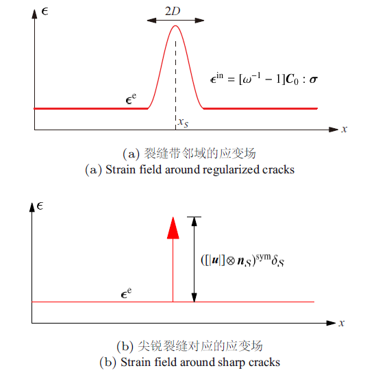
笔者之前的研究工作[87-89]表明: 非弹性材料发生应变局部化并最终形成尖锐裂缝应满足麦克斯韦变形协调条件, 即或者
这里$[| u|]$为裂缝的位移跳跃. 上述麦克斯韦变形协调条件如图3所示.
图3
 新窗口打开|下载原图ZIP|生成PPT
图3统一相场理论的应变局部化[60]
Fig.3Strain localization of the unified phase-field theory[60]
对于式(21)$_{1}$给出的应力-应变关系, 非弹性应变$\epsilon^{\rm in}$表示为
式中引入了单调递增的函数$\phi (d)$
由式(5)可知, 函数$\phi (d)$需满足如下条件
当裂缝尺度趋近于零即$b \to 0$时, 裂缝带$\mathcal{B}$内的应力几乎均匀分布. 于是, 由式(25)和式(26)给出
相应的内聚力确定为
其中, 局部化损伤变量$\varpi (d)$表示为
二阶对称张量$\boldsymbol{G}_{0} := \boldsymbol{n}_{\mathcal{S}} \cdot { E}_{0} \cdot \boldsymbol{n}_{\mathcal{S}}$为裂缝的初始刚度.
上述分析表明: 裂缝尺度$b \to 0$时, 统一相场理论收敛为一类同时考虑拉伸-剪切混合破坏行为的内聚裂缝模型[90-91]. 这一事实, 一方面展示了统一相场理论的合理性; 另一方面, 也为后文确定裂缝几何函数和能量退化函数提供了理论依据.
2 脆性断裂和准脆性破坏相场模型
上述统一相场理论中, 裂缝几何函数$\alpha (d)$和能量退化函数$\omega (d)$这两个特征函数决定了其分析结果. 本节针对脆性和准脆性这两种典型的固体结构破坏行为, 确定相应的特征函数, 并由此建立脆性断裂和准脆性破坏相场模型.2.1 解析解: 一般情况
为了确定统一相场理论的特征函数, 分析其单轴受拉情况下的解析解. 假设长度足够长的杆$x \in [-L, L]$, 其左、右两端作用单调递增且大小相等、方向相反的受拉位移. 不考虑杆的均布体积力.在开始阶段, 应变场沿杆长均匀分布, 直至杆内应力$\sigma$达到如下峰值$\sigma_{\rm c}$之前[56,59]
根据裂缝几何函数$\alpha (d)$和能量退化函数$\omega (d)$的性质, 峰值应力对应的裂缝相场$d_{\rm c} \in (0, 1)$和系数$\beta_{\rm c}$按以下三种情况给出[59]
(1) $\alpha' (0) = 0$且$\omega' (0) < 0$: 峰值应力对应的裂缝相场$d_{\rm c} = d_{\rm c1}$由下式确定
(2) $\alpha' (0) > 0$且$\omega' (0) < 0$: 峰值应力对应的裂缝相场$d_{\rm c} = d_{\rm c2}$确定为
(3) $\omega' (0) = 0$或$\phi' (0) = 0$: 峰值应力对应的裂缝相场$d_{\rm c}$在$d_{\rm c} = d_{\rm c1}$与$d_{\rm c} = d_{\rm c2}$二者之间选择, 即
这里应用了洛必达法则.
一般情况下($L \gg b$), 位移进一步增大会导致杆发生应变局部化并形成裂缝带. 不失一般性, 假设裂缝带中心位置位于$x_{0} = 0$处, 此处裂缝相场获得最大值并记为$d \big|_{x = 0} = d^{\ast}$; 相应裂缝带的范围为$[-D, D]$, 这里$D \ll L$为裂缝带半宽度, 其大小在损伤破坏过程中并不一定是常数. 此时, 杆内应力$\sigma$和裂缝带两侧的非弹性位移之差(即名义裂缝位移跳跃)$w (d^{\ast})$均可以表示为$d^{\ast}$的函数[56]
式(36)构成了参数化的应力-名义位移跳跃关系.
杆完全破坏即$d^{\ast} = 1$时, 最终裂缝相场逆分布$x (d_{u})$和裂缝带半宽度$D_{u}$分别表示为
即最终破坏时, 裂缝相场分布仅与函数$\alpha (d)$有关.
2.2 解析解: 特殊情况
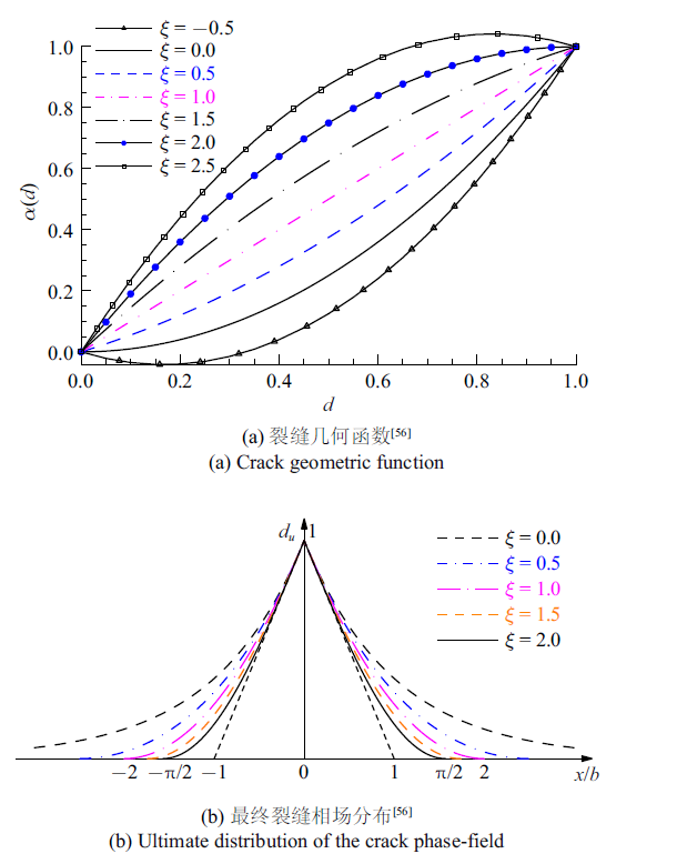
为了更好地说明上述解析解, 本节考虑如下满足条件(3)和(28)的最简函数形式[56]式中, $P (d) = 1 + a_{2} d + a_{3} d^{2} + \cdots$为多项式; 系数$\xi \in [0, 2]$, $a_{1} > 0, a_{2}, a_{3}, \cdots$以及指数$m > 0$均为待确定的模型参数. 需要指出的是, 为了保证裂缝几何函数(38a)满足$\alpha (d) \in [0, 1]$单调性递增条件, 参数$\xi$应在[0,2]范围内取值, 如图4(a)所示.
图4
 新窗口打开|下载原图ZIP|生成PPT
图4参数$\xi$取值对裂缝几何函数及最终裂缝相场分布的影响
Fig.4Effects of the parameter $\xi$ on the crack geometric function and the ultimate distribution of the crack phase-field
对于裂缝几何函数(38a), 由式(37a)可以给出最终破坏时裂缝相场分布$d_{u} (x)$和裂缝带半宽度$D_{u}$的解析表达式[56,59]. 特别对于典型参数$\xi$, 其最终裂缝相场分布$d_{u} (x)$如图4(b)所示. 可见, 随着参数$\xi \in [0, 2]$增大, 裂缝带半宽度$D_{u} (\xi)$逐渐减小.
此时, 由特征函数(38a)和(38b)的性质可以给出
这里系数$\tilde{\beta}_{\rm c}$与裂缝尺度$b$无关, 表示为
峰值应力对应的裂缝相场$d_{\rm c}$与参数$\xi \in [0, 2]$有关.
根据参数$a_{1} > 0$的取值, 考虑以下两种情况:
(1) 参数$a_{1}$与裂缝尺度$b$无关(记为$a_{1} = c_{1}$): 此时, 峰值应力$\sigma_{\rm c}$与裂缝尺度$b$的平方根成反比, 即
当裂缝尺度$b \to 0$时, 峰值应力$\sigma_{\rm c}$无穷大, 这一特性与经典线弹性断裂力学一致. 相应的, 统一相场理论退化为一类脆性断裂相场模型, 见2.2.1节.
与经典Griffith或Irwin线弹性断裂力学类似, 脆性断裂相场模型难以考虑裂缝起裂[22]. 为了解决这一难题, 峰值应力必须为有限大小. 最常用的方法是假定裂缝尺度参数$b$按下式确定[33,41,84]
式中, $f_{\rm t}$为材料的破坏强度(一般取为单轴抗拉强度); $l_{{\rm ch}} := E_{0} G_{{\rm f}} / f_{\rm t}^{2}$为表征固体材料脆性程度的Griffith或Irwin特征长度: 其值越小, 材料越脆. 对于脆性材料, 这一方法虽然能够描述裂缝起裂, 但存在以下主要缺点[49,58]: ①裂缝尺度$b$为材料属性而并非数值参数, 导致裂缝面积正则化公式(1)和整个模型失去$\varGamma$收敛性质; ②对于某些脆性材料, 由此确定的裂缝尺度$b$过大(如砂浆$b\approx50$ mm), 会导致裂缝面积计算精度不足、裂缝带过宽、破坏模式失真等问题, 从而高估裂缝能量耗散、结构承载力和延性等关键指标, 详见文献[50]中的讨论.
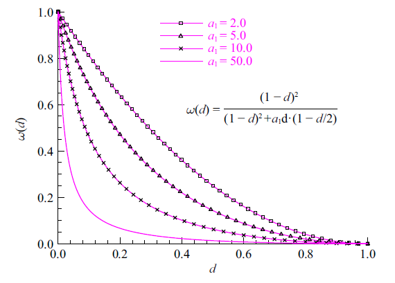
(2) 参数$a_{1}$与裂缝尺度$b$成反比: 为了保证峰值应力$\sigma_{\rm c}$为有限值(即材料破坏强度$f_{\rm t}$)且与裂缝尺度$b$无关, 由式(39)有
换句话说, $a_{1}$并非材料属性, 而是与裂缝尺度$b$成反比的数值参数. 此时, 所给出的模型仍然满足$\varGamma$收敛性质: 其值越小, 裂缝面积(式(1))的精度越高, 同时能量退化函数$\omega(d)$越陡峭(如图5所示), 裂缝对周边固体的影响范围也越小, 正则化裂缝越接近真实裂缝.
图5
 新窗口打开|下载原图ZIP|生成PPT
图5参数$a_{1} > 0$对能量退化函数$\omega (d)$的影响[58]
Fig.5Effects of the parameter $a_{1}$ on the energetic degradation function[58]
此种情况下, 当其他模型参数满足一定条件时, 统一相场理论可以退化为一类可以描述应变软化行为的准脆性破坏相场模型, 见2.2.2节所述.
2.2.1 脆性断裂
对于$a_{1} = c_{1}$为常数的脆性断裂相场模型, 可以考虑以下参数
即[23,30]
根据裂缝几何函数(38a)的性质, 有以下两种情况.
(1) 参数$\xi = 0$, 即$\alpha (d) = d^{2}$和$c_{\alpha} = 2$. 峰值应力对应的裂缝相场由式(33)确定
上述AT2模型由文献[23, 30]提出并经Miehe等[37]完善, 是最早应用于脆性断裂分析的相场模型.
(2) $\xi \in (0, 2]$: 此时, 由式(34)可以得到
常用模型有以下两种
这两种模型给出的应力-应变曲线均为理想弹脆性, 且裂缝相场为有限分布, 与实际情况较为相符, 因此在固体脆性断裂中的应用较为广泛[33].
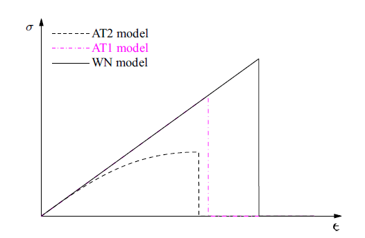
图6比较了上述不同脆性断裂相场给出的单轴受拉结果. 可见, AT2模型给出的应力-应变关系缺乏线弹性阶段, 这与线弹性断裂力学不一致, 而且最终破坏时裂缝相场的分布范围为$[-\infty, +\infty]$, 也与实际情况不符. 按式(42)确定裂缝尺度$b$后, AT1模型和WN模型虽然能够地描述脆性材料的起裂和裂缝扩展, 但无法考虑准脆性材料的损伤破坏行为.
图6
 新窗口打开|下载原图ZIP|生成PPT
图6不同脆性断裂相场模型给出的应力-应变曲线
Fig.6Stress-strain curves given by different phase-field models for brittle fracture
2.2.2 准脆性破坏
为了更好地解决裂缝起裂和准脆性破坏问题, 裂缝几何函数(38a)的参数取为$\xi \in (0, 2]$, 以保证裂缝相场为有限分布.
此时, 有$\alpha' (0) > 0$且$\omega' (0) < 0$. 相应的, 应力达到峰值$\sigma_{\rm c}$之前, 应变场沿杆全长均匀分布, 裂缝相场为零, 应力-应变关系为线弹性. 峰值应力$\sigma_{\rm c}$和对应的裂缝相场$d_{\rm c}$表示为
为了保证峰值应力$\sigma_{\rm c}$为有限值(即材料破坏强度$f_{\rm t}$)且与裂缝尺度$b$无关, 根据式(43)有
式中, 裂缝尺度$b$为数值参数, 其取值越小, 裂缝面积(1)的精度越高; 其取值小于某一上限值后, 对计算结果几乎不产生影响.
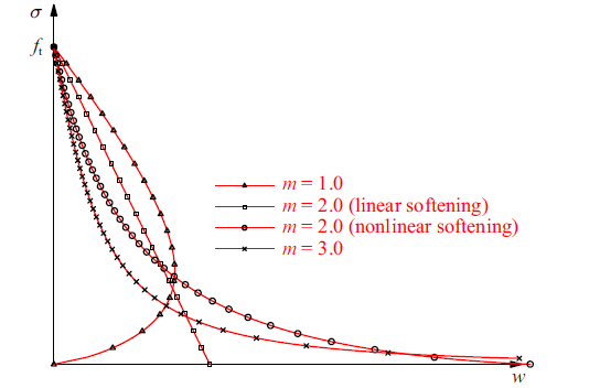
随着施加的位移进一步增大, 杆内会出现应变局部化和裂缝相场非均匀分布, 应力-名义裂缝位移跳跃曲线$\sigma (w)$由式(36)给出, 如图7所示.
图7
 新窗口打开|下载原图ZIP|生成PPT
图7准脆性破坏相场模型给出的应力-名义位移跳跃曲线[56]
Fig.7Stress-displacement (apparent) jump curves given by different phase-field models for quasi-brittle fracture[56]
软化曲线$\sigma (w)$的初始斜率$k_{0}$和极限张开位移$w_{\rm c}$确定为[56]
此外, 裂缝带半宽度的初始值$D_{0}$表示为
其中, $P (1) = 1 + a_{2} + a_{3} + \cdots$为多项式$P (d)$在$d = 1$时的取值. 从式(37)和式(53)可以看出, 裂缝带宽度与裂缝尺度$b$成正比.
由图7和式(52)可知: $m < 2$给出的极限裂缝张开位移为零, 即软化曲线出现回跳, 这与准脆性破坏特征不符. 因此, 能量退化函数(38b)中的指数参数$m$的取值范围为
具体而言, $m > 2$给出的极限裂缝张开位移$w_{\rm c}$无穷大, 而$m = 2$给出的$w_{\rm c}$为有限值.
上述情况下, 统一相场理论可以给出合理的软化曲线, 其破坏强度$f_{\rm t}$、初始斜率$k_{0}$和断裂能$G_{{\rm f}}$均为有限值, 表现出典型的准脆性破坏特征.
2.3 相场正则化内聚裂缝模型
上述结果表明, 为了合理反映损伤破坏过程中的应变软化段, 应采用如下裂缝几何函数和能量退化函数式中, 参数$\xi \in (0, 2]$以及$m \geqslant 2$, 且$a_{1} > 0, a_{2}$和$a_{3}$确定为[56]
此时, 式(36)给出的应力-名义位移跳跃曲线$\sigma (w)$与裂缝尺度$b$无关, 而仅取决于弹性模量$E_{0}$、破坏强度$f_{\rm t}$、断裂能$G_{{\rm f}}$以及软化段参数(如初始斜率$k_{0}$、裂缝极限位移$w_{\rm c}$)等材料属性. 由此, 对于裂缝几何函数和能量退化函数(55), 统一相场理论给出了一类相场正则化内聚裂缝模型. 例如, 文献[64]选用$\xi = {1}/{2}$即PF$^{{1}/{2}}$-CZM, 并应用于飞机除冰优化设计; 文献[94,95,96]选用$\xi = 1$即PF$^{1}$-CZM, 并应用于混凝土和岩石等准脆性材料结构. 然而, 这些模型均无法应用于线性软化.
理论上, 对于所有的参数$\xi \in (0, 2]$上述相场正则化内聚裂缝模型都成立. 然而, 不同参数$\xi$对应的模型适用范围有所不同. 特别是, 裂缝相场不可逆$\dot{d} \geqslant 0$要求: 裂缝带半宽度初始值$D_{0}$不能超过其最终值$D_{u}$, 即[56]
基于上述考虑, 笔者建议采用如下裂缝几何函数
参数$a_{1} > 0$, $a_{2}$和$a_{3}$仍由关系式(56)给出, 即
这里$\beta_{k}$和$\beta_{\rm w}$分别表示为
$\begin{eqnarray*} \beta_{k} : = \dfrac{2k_{0}}{-f_{\rm t}^{2} / G_{{\rm f}}} \geqslant 1, \ \ \beta_{\rm w} : = \dfrac{w_{\rm c}}{2 G_{{\rm f}} / f_{\rm t}} \end{eqnarray*}$
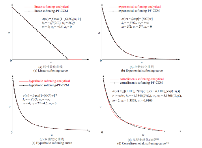
对于线性软化, 有$\beta_{k} = \beta_{\rm w} = 1$. 此时, 式(36)给出的典型软化曲线如图8所示. 可以看出, 尽管$P(d)$只采用了二次多项式, 线性软化、指数软化和双曲线软化等均得到了高精度的描述, 混凝土科内列森软化曲线[61]也相当吻合; 其他如双线性等软化曲线也可以类似得到, 见文献[62]. 因此, 参数$\xi = 2$对应的相场正则化内聚裂缝模型PF$^{2}$-CZM最为完备, 且能够广泛适用于各类常用软化曲线, 在混凝土[62]、玻璃[65]、PMMA[58]、复合材料[66-67]、橡胶[68-69]、岩石[63]等多种固体材料结构中得到成功应用.
图8
 新窗口打开|下载原图ZIP|生成PPT
图8相场正则化内聚裂缝模型 PF$^{2}$-CZM 给出的软化曲线[56]
Fig.8Softening curves given by the phase-field regularized cohesive zone model (PF$^{2}$-CZM)[56]
在计算量允许的条件下, 裂缝尺度$b$的取值越小,裂缝面积式(1)以及相应能量耗散的计算精度越高. 极限情况下, 当裂缝尺度$b \to 0$时, 裂缝带宽度也趋近于零, 统一相场理论退化为1.5节的内聚裂缝模型. 因此, 相场正则化内聚裂缝模型不仅适用于准脆性破坏, 还可采用线性软化描述脆性断裂[58], 实现了两种典型破坏特征的统一反映.
3 数值实现和求解算法
统一相场理论数值实现时, 可以将偏微分控制方程(15)转化为其弱形式: 求解满足边界条件$\boldsymbol{u} (\boldsymbol{x} \in \partial \varOmega_{u}) = \boldsymbol{u}^{\ast}$和不可逆条件$\dot{d} (\boldsymbol{x}) \geqslant 0$的位移场和裂缝相场$(\boldsymbol{u}, d)$, 使得下式对于任意容许的位移场和裂缝相场$(\delta \boldsymbol{u}, \delta d)$均成立与位移边界条件类似, 裂缝相场$d (\boldsymbol{x})$也可以施加诸如$d (\boldsymbol{x} \in \varOmega \backslash \mathcal{B}) = 0$或$d (\boldsymbol{x} \in \mathcal{S}_{0}) = 1$等强制边界条件, 这里$\mathcal{S}_{0}$为初始预制裂缝.
3.1 多场有限元数值实现
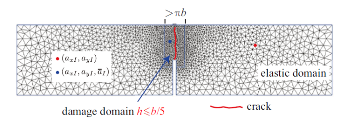
式(60)是关于位移场$\boldsymbol{u} (\boldsymbol{x})$和裂缝相场$d (\boldsymbol{x})$的耦合方程, 通常采用多场有限元方法进行数值求解.在有限元空间离散时, 可以将整个计算区域内所有的单元节点均赋予位移和裂缝相场自由度, 也可以如图9所示将整个计算域分为两部分[97]以提高计算效率, 即: 可能出现裂缝的相场子区域$\mathcal{B}^{h}$以及剩余弹性部分$\varOmega^{h} \backslash \mathcal{B}^{h}$, 对于前者, 单元节点同时具有位移自由度和裂缝相场自由度, 而后者的单元节点仅有普通位移自由度. 已有研究表明[56-58,62,79], 为保证计算精度, 一般相场子区域$\mathcal{B}^{h}$内的单元大小一般取$h \leqslant b/5$. 由于固体开裂后会发生剧烈的变形局部化, 相场模型的数值实现必须反映裂缝带内相场变量的梯度变化, 这对网格大小提出了要求. $\varGamma$ -收敛分析表明[30]: 由于有限元空间离散的数值误差, 正则化关系式(1)将高估裂缝面积约$h/(c_{\alpha} b)$. 为减少计算量, 已有相场模拟大多采用$h = b / 2$, 此时将高估裂缝面积16%$\sim$25%左右. 出于计算精度的考虑, 笔者[56]建议采取$h \leqslant b/5$, 相应裂缝面积或能量耗散的误差控制在6%$\sim$10%以内. 这一取值也得到了数值模拟结果的验证[62,79,97]和其他****[33,50,98]的采纳. 在实际工程应用中, 若需要采用较粗的有限元网格, 可通过减小材料断裂能等方式[70], 部分补偿有限元空间离散引起的数值误差.
图9
 新窗口打开|下载原图ZIP|生成PPT
图9计算区域的有限元空间离散[97]
有限元空间离散后, 位移场和应变场、裂缝相场及其梯度分别表示为(在数值实现中, 张量均采用Voigt标记)
Fig.9Finite element discretization of the computational domain[97]
其中, 列向量$ a:= \{ a_{I} \}^{{\rm T}}$表示整个计算域$\varOmega^{h}$所有单元节点$I$的位移自由度, 位移插值形函数矩阵和位移-应变协调矩阵分别记为$ N := \big[ N_{I} I \big]$和$ B:= \big[ \boldsymbol{B}_{I} \big]$; 类似的, 列向量$\bar{ a} := \big\{ \bar{a}_{J} \big\}^{{\rm T}}$表示相场子域$\mathcal{B}^{h}$所有单元节点$J$的裂缝相场自由度, 相场插值形函数矩阵及相场梯度协调矩阵分别记为$\bar{ N}:= \big[ \bar{N}_{J} \big]$和 $\bar{ B} = \big[ \bar{ B}_{J} \big]$. 为简单起见, 位移场和裂缝相场通常采用相同的插值形函数, 即$\bar{N}_{J} (\boldsymbol{x}) = N_{J} (\boldsymbol{x})$.
于是, 由控制方程的弱形式(60)可以给出如下平衡方程
式中, $ f^{{\rm ext}}$为标准外力列向量[99]. 由于裂缝相场演化的不可逆性质, 其平衡方程为不等式, 需要在数值求解时加以处理.
方程组(62)通常采用增量迭代法进行求解, 即将时间步$[0, T]$划分为$N$个子步$[t_{n}, t_{n+1}]$, 这里$n = 0, 1, \cdots, N-1$. 对于时间增量为$\Delta t := t_{n+1} - t_{n}$的典型子步$[t_{n}, t_{n+1}]$, $t_{n}$时刻所有的状态变量已知, 在此基础上采用迭代方法求解$t_{n+1}$时刻的状态变量.
对于考虑惯性力的动力平衡方程, 有限元离散后的控制方程表示为
式中$\ddot{ a}:= {\rm d}^{2} a / {\rm d}t^{2}$为单元节点的加速度列向量, $ M := \int_{\varOmega} N^{{\rm T}} \rho N{\rm d}V$为一致质量矩阵. 此时, 可以采用隐式算法(如Newmark-$\beta$法、HHT-$\alpha$法等), 将上述常微分方程转换为节点位移$ a$的非线性代数方程进行求解, 也可以采用显式动力积分方法, 直接计算节点位移. 具体步骤详见文献[59].
3.2 裂缝相场演化不可逆性
为了处理裂缝相场演化的不可逆性, 研究人员提出了增广拉格朗日[100]、罚函数[101]等多种方法, 但前者会引入新的自由度, 而后者存在罚刚度选用难题. 这里介绍另外两种较为常用的方法, 即约束优化方法和历史最大变量方法.(1) 在有限元方法和增量求解算法的框架内, 相场子区域$\mathcal{B}^{h}$内每个单元节点$J$均满足不可逆条件, 即$0 \leqslant \bar{a}_{{J, n}} \leqslant \bar{a}_{{J, n + 1}} \leqslant 1$, 这里下标$n$和$n+1$分别表示$t_{n}$和$t_{n+1}$时刻. 相应的, 裂缝相场子问题(62)$_{2}$可改写为如下约束优化问题[102-104]
并采用减缩空间激活集牛顿方法[105]等约束优化求解器进行求解, 此时迭代求解过程仅需考虑等式(64)$_{1}$. 具体过程见开源工具箱Petsc[106]中的非线性求解器Snes.
(2) 受损伤力学[40]的启发, 将式(15b)的有效能量释放率$\bar{Y}$替换为其历史最大值$\mathcal{H}$, 即[37]
这里, $\bar{Y}_{0} = \frac{1}{2} f_{\rm t}^{2} / E_{0}$表示$\bar{Y}$的初始阈值, 即当且仅当条件$\bar{Y} > \bar{Y}_{0}$满足时才会出现裂缝. 此时相场子问题(62)$_{2}$转化为可采用常规求解器求解的等式.
上述两种方法的共同点是将裂缝相场子问题不等式(62)$_{2}$变为等式, 即
式中, 列向量${ z} := \big\{ { a}, \bar{{ a}} \big\}^{{\rm T}}$为待求的节点位移和裂缝相场自由度. 二者的区别在于, 约束优化方法仅针对预先判断处于加载状态的节点进行迭代, 而历史最大变量方法则针对所有相场自由度.
3.3 控制方程的数值求解
为了求解非线性代数方程组(66), 可以考虑以下三种数值算法: 整体牛顿迭代算法、子问题交错迭代算法以及整体BFGS拟牛顿迭代算法.3.3.1 整体牛顿迭代算法
对于牛顿迭代算法, 将平衡方程(66)进行整体线性化后给出
子刚度矩阵分别表示为
由于所有被积分函数均连续, 可采用标准高斯数值积分方法进行数值计算.
需要指出: 由于系统总能量(17)是整体未知量${ z} := \big\{ { a}, \bar{{ a}} \big\}$的非外凸函数[23,30], 上述整体牛顿迭代算法的收敛性难以保证. 为此, 研究人员提出了基于裂缝面积的弧长法[53,107]、反常线性搜索[108]、自适应修正牛顿方法[109-110]等, 但效果均不十分理想.
对于弱耦合非线性问题, 通常可以忽略非对称项, 即
已有研究表明[110], 对于具有强非线性和强耦合特征的相场断裂模型, 这种忽略耦合项的修正牛顿迭代算法效果也很差.
3.3.2 子问题交错迭代算法
虽然系统总能量(17)是整体未知量$(\boldsymbol{u}, d)$的非外凸函数, 但却分别单独是位移场$\boldsymbol{u}$或裂缝相场$d$的外凸函数[23,30]. 因此, 可以通过交错迭代算法进行求解式(62). 对于某一时间增量步$[t_{n}, t_{n+1}]$, 以第$k$次迭代过程为例, 有
(1) 固定相场自由度$\bar{{ a}} = \bar{{ a}}^{(k-1)}$, 求解式(66)$_1$的一式得到节点位移${ a}$, 即
上述位移子问题可以通过牛顿迭代方法进行求解, 其线性化方程表示为
刚度矩阵${ K}_{uu}$由式(68)给出.
(2) 利用上述求得的节点位移${ a}^{(k)}$, 通过相场子问题(66)$_{2}$求解相场自由度$\bar{{ a}}$, 即
其线性化方程表示为
刚度矩阵${ K}_{dd}$由式(68c)给出.
上述求解过程交替往复, 直至最后达到收敛, 具体过程详见[59,79]. 收敛判据可以采用以下几种.
(1) 不迭代一次过[38]: 将相场模型视为裂缝相场-位移场的顺序耦合问题, 不检查整个控制方程是否收敛. 这种方法虽然得到了广泛应用[111-113], 但必须采取极小的时间步长(通常为$10^{-5} \!\sim\! 10^{-7}$量级)才能保证计算精度; 更糟糕的是, 这种方法会延缓裂缝扩展, 从而可能导致不准确甚至错误的数值结果.
(2) 基于裂缝相场的收敛准则[23,30,84]: 当连续两次整体迭代后的裂缝相场足够接近时判断为收敛, 即$\big| \bar{a}^{(k + 1)} - \bar{a}_{n+1}^{(k)} \big|_{2} < \epsilon$, 这里$| \cdot |_{2}$为$L_{2}$范数, 容差可取为$\epsilon = 1.0 \times 10^{-5}$.
(3) 基于能量的收敛准则[108,114]: 类似于上述裂缝相场收敛准则, 检查连续两次整体迭代后的系统总能量(17), 当二者足够接近时即判断为达到收敛标准. 由于系统总能量对裂缝相场不敏感, 采用该收敛准则需非常小心, 详见文献[114].
(4) 基于残差的收敛准则[66,108,110,115]: 每次整体迭代结束后检查平衡方程(66)的残差${ r}$和$\bar{{ r}}$判断是否收敛. 这种收敛准则非常便于在商业有限元软件中实现.
与整体牛顿迭代或修正牛顿迭代算法相比, 子问题交错迭代算法具有很好的数值健壮性, 特别是与局部弧长法[116]联合使用其收敛性还可以进一步提高[79]. 然而, 该算法的收敛速度较慢, 某些关键增量步甚至需要上千次整体迭代, 求解效率无法满足大规模计算要求.
为了克服子问题交错迭代算法计算效率低的问题, 文献[104]提出了一种复合算法, 即在某一增量步的开始阶段采用子问题交错迭代算法, 一旦判断求解进入收敛半径后换用整体牛顿迭代算法. 然而, 这种复合算法的转换时刻缺乏理论依据, 因而只能针对具体问题进行试算, 难以实现通用化[56-57], 其数值实现也非常复杂.
3.3.3 整体BFGS拟牛顿迭代算法
由于系统总能量泛函非外凸, 整体牛顿迭代或修正牛顿算法的收敛性非常差; 子问题交错迭代算法具有很好的收敛性, 但其收敛速度慢、计算效率低. 近年来, 笔者首次将整体BFGS(Broyden-Fletcher-Goldfarb-Shanno)拟牛顿迭代算法[117]应用于统一相场理论控制方程的求解, 在保证算法收敛性的同时, 收敛速度和计算效率大幅度提升.
在求解非线性方程组${ g} ({ z}) = {{\bf 0}}$时, BFGS拟牛顿迭代算法通过如下递推公式更新计算刚度矩阵
或等效的柔度矩阵
这里, $\delta { g} := { g}^{(k)} - { g}^{(k-1)}$ 和$\delta { z} := { z}^{(k)} - { z}^{(k-1)}$分别为第$k$次迭代结束后的残量和修正量.
可以证明[118], 若初始刚度矩阵$\tilde{{ K}}^{(0)}$对称且正定, 则更新后的矩阵$\tilde{{ K}}$同样如此. 因此, 初始刚度$\tilde{{ K}}^{(0)}$可以采用式(67)
与整体修正牛顿迭代算法不同, 虽然上述初始刚度忽略了耦合项的影响, 更新后的刚度矩阵仍然能够考虑裂缝相场-位移场之间的耦合. 此外, 为了更加合理地反映耦合项的影响, 可以构造更准确的初始刚度矩阵, 进一步提升计算效率[143].
在实际计算中, BFGS拟牛顿迭代算法往往与线性搜索联合使用[117], 并根据需要设置间隔一定迭代次数(通常为$5\,\sim\,10$次)才对刚度矩阵$\tilde{{ K}}$进行更新计算. 因此, 所需迭代次数可能比牛顿迭代算法更多(在后者能够收敛的前提下), 但由于BFGS算法无需每次迭代都更新刚度矩阵且计算过程较为简单, 计算效率通常反而更高. 较之广泛采用的子问题交错迭代算法, 整体BFGS算法的求解效率可以提高5$\sim$8倍[71-73].
3.4 数值实现平台
从上述数值算法可以看出, 统一相场理论非常便于通过有限元方法加以实现, 且其二维和三维数值实现几乎没有区别. 比较常用的开源和商业有限元计算平台有:(1) Matlab: 借助Matlab软件友好的开发环境和强大的图形处理功能, 文献[45,119]等实现了脆性断裂相场模型AT2, 并应用于固体的静力和动态裂缝扩展分析.
(2) Feap: 该有限元软件采用Fortran语言编程, 被广泛应用于学术研究. 文献[120,121]基于该平台实现了脆性断裂相场模型AT2.
(3) Mef90: 文献[70]针对脆性断裂相场模型} AT1/2, 采用Fortran90语言开发了该软件. 特别是, 为保证系统总能量取得全局最小值, 该软件采用了回溯搜索算法.
(4) Deal.II: 是一种C++编程的开源有限元平台, 支持有限元网格的自适应细分, 且通过PETSC工具包[106]提供了约束优化求解器. 文献[109, 122]在该平台上实现了脆性断裂相场模型AT2, 并通过网格自适应提升计算效率.
(5) FENICS: 是一种C++和PYTHON混合编程的开源有限元平台, 用户仅需提供系统的总能能量泛函或控制方程的弱形式, 非常便于相场模型的初步验证. 利用这一平台, 文献[104, 123]等实现了脆性断裂相场模型AT1, 并进行了静力和动力裂缝扩展分析.
(6) MOOSE: 采用C++编程, 是一种应用广泛的多场耦合分析平台. 基于该平台,文献[124,125]针对脆性断裂相场模型AT2、文献[126]针对准脆性破坏 PF$^{1}$-CZM 分别进行了数值实现.
(7) Jive: 是一种C++编程的开源有限元软件平台, 非常便于自定义材料和自定义单元二次开发. 笔者和合作者[49,59,65]基于该平台实现了统一相场理论, 开发了约束优化求解器和BFGS拟牛顿算法, 并将其应用于静力、动态以及多场耦合条件下的裂缝扩展分析.
由于大多针对研究目的, 上述数值实现平台通常采用GMSH[127]、PARAVIEW[128]等开源软件进行前后处理, 不便于工程应用.
为此, 部分****基于ABAQUS[127], COMSOL[131]等商业软件进行二次开发, 实现了相场断裂模型AT2. 然而, 受软件接口限制, 这些数值实现大多仅适用于脆性断裂相场模型, 且通常采用一次过不迭代或整体牛顿迭代算法, 计算效率不高且计算精度难以保证.
最近, 笔者通过用户自定义材料接口UMAT和用户自定义单元接口UEL, 分别采用子问题交错迭代算法和整体BFGS拟牛顿算法, 首次在ABAQUS软件平台实现了包括AT1/2和PF-CZM等在内的各种相场模型[71]. 相关源代码已在网上公开, 可供研究人员免费下载使用(https://github.com/jianyingwu/pfczm-abaqus).
4 应用算例
本节给出统一相场理论在脆性和准脆性结构损伤破坏分析方面的若干验证和应用算例. 所有数值模拟均采用2.3节给出的相场正则化内聚裂缝模型(PF$^{2}$-CZM, 对应于$\xi = 2$). 对于脆性破坏, 采用线性软化曲线, 此时仅 PF$^{2}$-CZM 能严格保证裂缝相场演化的不可逆性质; 对于混凝土, 采用科内列森软化曲线. 所有二维问题假定为平面应力, 网格划分采用四节点双线性单元; 三维问题采用八节点实体单元. 所有数值模拟均在小型高性能计算工作站(配置: Intel(R) Core(TM) i7-7700HQ CPU@2.80 GHz中央处理器、512 GB内存)上完成.4.1 脆性破坏分析[58]
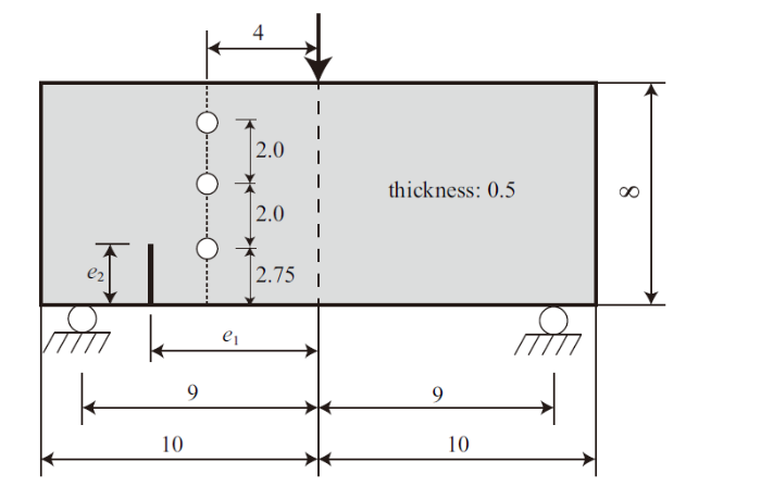
首先考虑一组非对称缺口开孔梁三点弯试验, 该实验由国际著名断裂力学****Ingraffea教授课题组[132-133]开展, 已成为线弹性断裂力学的标准算例之一. 特别是, 该系列试验受预制裂缝与孔洞之间的距离影响较大, 因此对分析模型的要求较高.试件几何尺寸如图10所示, 预制缺口的宽度为0.05 in; 小孔直径均为0.5 in (1 in = 2.54 cm), 试件由同一批PMMA脆性材料加工制作.文献[132]给出的材料参数分别为: 弹性模量$E_{0} = 4.75 \times 10^{5}$ psi (1 psi = 6.895 kPa), 泊松比$\nu_{0} = 0.35$, 断裂能$G_{{\rm f}} = 1.8$ lbf/in (1 lbf/in = 0.113 N$\cdot$m). 数值模拟采用$b = \big\{ 0.025, 0.050 \big\}$ in两种裂缝尺度, 相场子区域的有限元网格大小$h = 0.005$ in; 总单元数约67万, 计算时间约为20.3 h.
图10
 新窗口打开|下载原图ZIP|生成PPT
图10非对称缺口开孔梁三点弯试验: 试件尺寸(长度单位: in, 1 in = 2.54 cm)、载荷和边界条件[132]
Fig.10Asymmetrically notched three-point bending beams: Specimen dimensions (unit: in, 1 in = 2.54 cm), loading and boundary conditions[132]
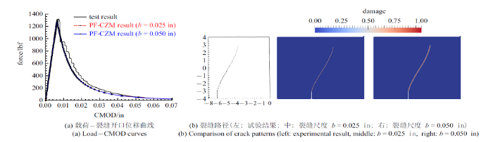
试验并未测定材料的破坏强度$f_{\rm t}$, 但给出了编号 0 的未开孔试件(预制裂缝偏心距$e_{1} = 6$ in, 裂缝高度$e_{2}$ = 1 in)的载荷-裂缝开口位移曲线, 因此先对该试件进行分析. 由图11可以看出, 材料破坏强度取为$f_{\rm t} = 2500$ psi(对应的材料特征长度$l_{{\rm ch}} = 0.14$ in), 计算给出的载荷-裂缝开口位移曲线和裂缝路径均与试验结果吻合良好. 此外, 只要保证裂缝面积(1)和能量耗散(17)的计算精度(满足条件$h \leqslant b/5$), 裂缝尺度对数值模拟结果几乎没有影响, 这一结论对于固体损伤破坏分析至关重要.
图11
 新窗口打开|下载原图ZIP|生成PPT
图11非对称缺口开孔梁三点弯试验: 试件0数值模拟结果[58]
Fig.11Asymmetrically notched three-point bending beams: Numerical results of Specimen 0[58]
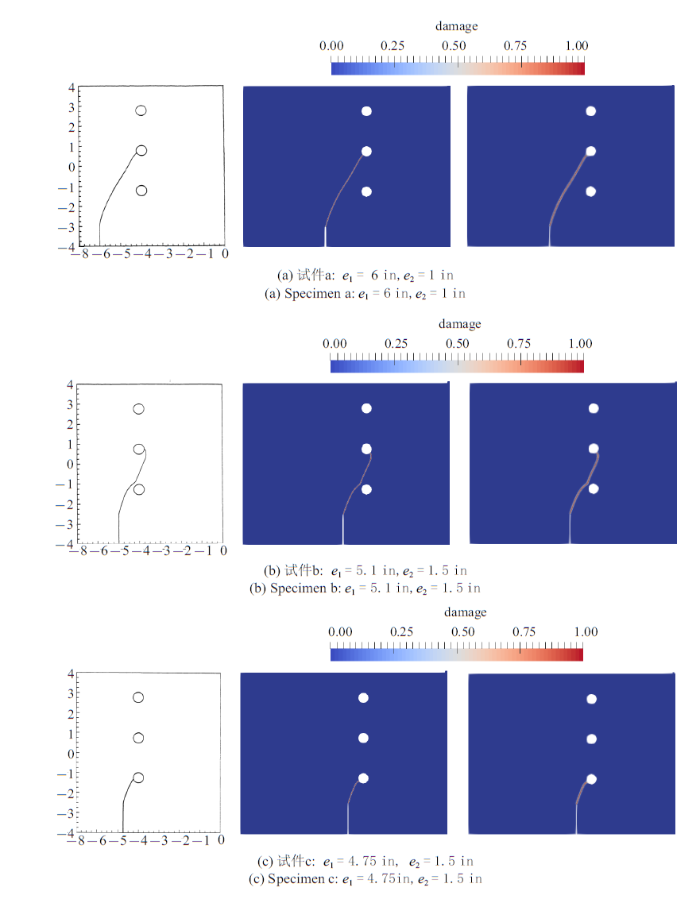
接下来考虑其他3种开孔试件(每个试件均带有3个直径为0.05 in的小孔). (1) 试件a: $e_{1} = 6$ in, $e_{2} = 1$ in; (2) 试件b: $e_{1} = 5.1$ in, $e_{2} = 1.5$ in; (3) 试件c: $e_{1} = 4.75$ in, $e_{2} = 1.5$ in.
除试验给出的材料参数外, 数值模拟中材料破坏强度取为$f_{\rm t} = 2500$ psi, 采用基于裂缝开口位移(CMOD)的局部弧长法进行加载, 以跟踪梁的损伤破坏全过程.
由于试验并未给出这些试件的载荷-位移曲线结果, 这里仅讨论裂缝路径. 试件a的数值模拟结果与试验结果的对比如图12(a)所示. 可以看出, 二者的吻合结果十分良好, 特别是能够再现底部小孔附近局部应力集中引起裂缝路径的细微变化. 随着预制裂缝与底部开孔的距离缩短, 局部应力集中引起的裂缝路径扰动更加明显, 但裂缝仍能绕过底部开孔继续向上扩展直到到达中间第二个开孔, 见图12(b); 当二者的距离进一步缩短时, 局部应力集中的影响进一步加强, 裂缝直接与底部开孔交汇, 如图12(c)所示. 同样, 裂缝尺度仅影响裂缝带的宽度, 对数值模拟结果没有影响.
图12
 新窗口打开|下载原图ZIP|生成PPT
图12非对称缺口开孔梁三点弯试验: 裂缝扩展路径对比(最左列: 试验结果; 中间列: 裂缝尺度$b = 0.025$ in; 最右列: 裂缝尺度$b = 0.050$ in)[58]
Fig.12Asymmetrically notched three-point bending beams: Comparison of crack patterns (left: experimental result, middle: $b=0.025$ in, right: $b = 0.050$ in)[58]
4.2 准脆性破坏分析[97]
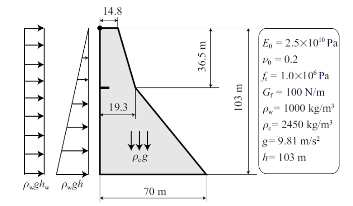
1967年, 位于印度的Koyna混凝土重力坝遭受里氏6.5级地震作用, 导致坝体迎水面(高度在背水面变坡度处)出现一条裂缝. 该混凝土重力坝的几何尺寸如图13所示, 裂缝长度为1.93 m. 为评估该受损结构的安全性能, 这里对大坝在洪水溢流工况下的承载力和损伤破坏过程进行分析.图13
 新窗口打开|下载原图ZIP|生成PPT
图13Koyna混凝土重力坝溢流破坏: 几何尺寸、边界和载荷条件
Fig.13Overflow of Koyna dam: Dimensions (unit: m), loading and boundary conditions
根据文献[134], 数值模拟中混凝土材料参数分别为: 密度$\rho = 2450$ kg/m$^{3}$, 杨氏模量$E_{0} = 2.5 \times 10^{4}$ MPa, 泊松比$\nu_{0} = 0.20$, 破坏强度$f_{\rm t} = 1.0$ MPa, 断裂能$G_{{\rm f}} = 100$ J/m$^{2}$, 对应的材料特征长度$l_{{\rm ch}} = 2.5$ m. 荷载施加分为三个荷载步: 重力载荷、三角形分布的满水库静水压力以及不断增加的矩形均布载荷(模拟溢流水压力); 前两步均直接采用载荷控制, 第三步采用基于左上角坝顶水平位移的间接位移加载控制, 以便跟踪整个裂缝扩展全过程.
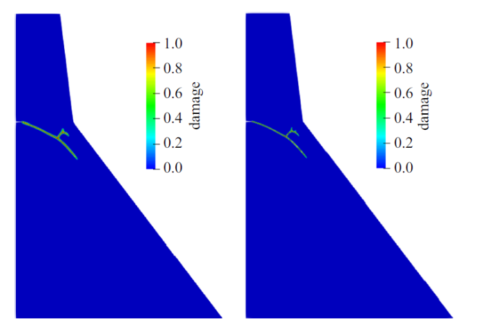
数值模拟考虑$b = \big\{ 0.3, 0.2 \big\}$ m两种裂缝尺度参数, 相场子区域的有限元网格大小取为$h = b/5$; 总单元数分别约16.5万和36.1万, 计算时间分别约为3.2 h和11.8 h. 从图14可以看出, 裂缝带宽度随着裂缝尺度$b$的减小而变窄, 但裂缝扩展路径不受影响: 从初始裂缝尖端开始, 裂缝沿着大致平行于背水面的方向斜向下扩展. 有趣的是, 由于重力坝的特点, 坝体下部压应力逐渐变大, 因此裂缝达到一定的深度后不再继续向下扩展, 而是在距背水面变坡度最近的位置发生分叉; 分叉裂缝发展到一定程度后, 由于背水面变坡度位置局部压应力的影响, 裂缝会发生二次分叉等复杂的损伤破坏行为, 使得整个结构的总能量最小.
图14
 新窗口打开|下载原图ZIP|生成PPT
图14Koyna混凝土重力坝溢流破坏: 裂缝扩展路径[97]
Fig.14Overflow of Koyna dam: Predicted crack patterns[97]
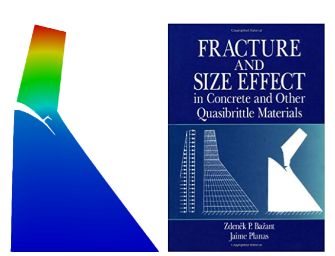
当左上角坝顶水平位移达到75 mm时, 大坝结构变形如图15所示. 这一数值模拟结果与内聚裂缝模型分析给出的结果一致(见美国Ba?ant教授撰写的专著[15]封面图片). 然而, 内聚裂缝模型需要预设裂缝路径并进行复杂繁琐的网格重划分, 而广泛采用的扩展有限元方法则无法预测上述裂缝分叉现象[134]. 截然不同的是, 无需其他任何处理手段, 相场正则化内聚裂缝模型即可自然地预测上述复杂的裂缝扩展引起的结构损伤破坏行为.
图15
 新窗口打开|下载原图ZIP|生成PPT
图15Koyna混凝土重力坝溢流破坏: 左侧坝顶水平位移75 mm时的结构变形图
Fig.15Overflow of Koyna dam: Deformations when the horizontal displacement of the crest node reaches 75 mm
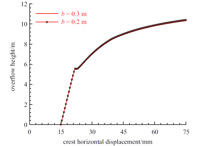
不同裂缝尺度给出的溢流高度-坝顶水平位移曲线如图16所示. 可以看出, 裂缝尺度参数对计算结果几乎没有影响: 溢流高度较小(低于5.5 m)时, 坝顶水平位移基本呈线性变化; 裂缝快速扩展时, 结构所能抵抗的溢流高度会出现短时降低; 裂缝进入稳定扩展阶段, 坝顶水平位移随溢流高度增大而非线性增长, 并逐渐趋于某一极限值.
图16
 新窗口打开|下载原图ZIP|生成PPT
图16Koyna混凝土重力坝溢流破坏: 溢流高度-坝顶水平位移[97]
Fig.16Overflow of Koyna dam: Curves of the overflow height-horizontal displacement of the crest[97]
4.3 动力破坏分析[135]
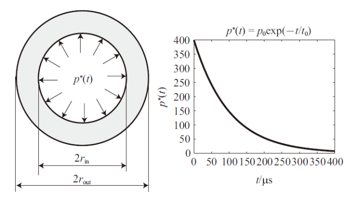
接下来考虑如图17所示的内部冲击载荷作用下厚壁圆柱的动态破碎问题[136-137].图17
 新窗口打开|下载原图ZIP|生成PPT
图17厚壁圆柱动态破碎问题: 几何尺寸(左)和载荷时程(右). 圆柱内外半径分别为$r_\text{in}=80 \;\text{mm}$和$r_\text{out}=150 \;\text{mm}$, 平面外厚度为70 mm. 冲击载荷的幅值为$p_0=400\;\text{MPa}$, 参数$t_0=100$ $\mu$s
Fig.17Fragmentation of a thick cylinder: Geometry (left) and the loading history (right). The innner and outer radii are $r_\text{in}=80 \;\text{mm}$ and $r_\text{out}=150 \;\text{mm}$, and the thickness is 70 mm. For the impact pressure, the amplitude is $p_0=400\;\text{MPa}$ and the parameter is $t_0=100$ $\mu$s
根据文献[137]中的讨论, 考虑材料断裂能$G_{\rm f}$服从如下Weibull分布
式中, 平均断裂能$G_{\rm f0} = 20$ N/mm; $Rand$为[0, 1]之间的随机数, 指数取为$m = 2$. 基于类似的考虑, 文献[95, 138]考虑弹性模量的随机分布. 其他材料参数均由文献[139]给出: 密度$\rho = 7850$ kg/m$^{3}$, 杨氏模量$E_{0} = 2.1 \times 10^{5}$ MPa, 泊松比$\nu_{0} = 0.30$, 破坏强度$f_{\rm t} = 1000.0$ MPa.
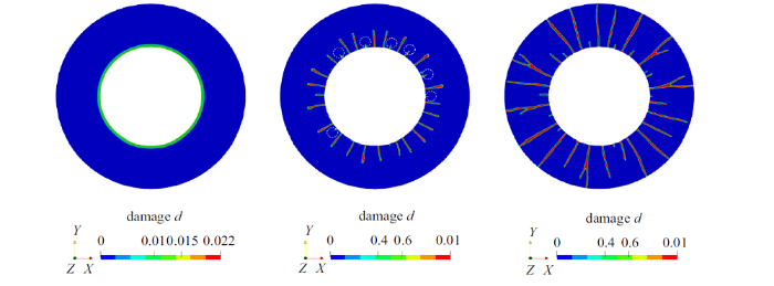
数值模拟采用裂缝尺度$b = 1.0$ mm, 有限元网格大小统一取为$h = 0.2$ mm; 总单元数约162万, 计算时间约为64.2 h. 动力平衡方程求解采用显式求解器并行计算, 模拟给出的破碎演化过程如图18所示: 在$t \approx 55$ $\mu$s时刻, 内边缘的裂缝相场几乎均匀分布, 随后裂缝继续沿径向向外边缘扩展; 在$t= 70$ $\mu$s时刻, 受有限元网格划分和材料参数随机性以及两条主裂缝间压应力的影响, 有的裂缝停止扩展, 部分裂缝则继续扩展直至圆柱外边缘; 裂缝扩展过程中还会出现如图18所示的分叉.
图18
 新窗口打开|下载原图ZIP|生成PPT
图18厚壁圆柱体动态破碎问题: 破碎演化过程[135]
Fig.18Fragmentation of a thick cylinder: Cracks evolution process[135]
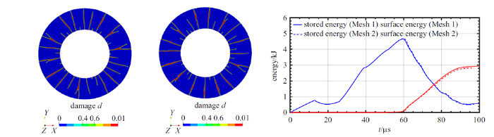
为了分析有限元网格大小的影响, 裂缝尺度参数同样取为$b = 1$ mm, 但考虑$h = \big\{0.2, 0.15 \big\}$ mm两种网格尺寸; 总单元数分别约162万和288.5万, 计算时间分别约为64.2 h和121.6 h. 数值模拟给出的结果如图19, 两种有限元网格尺寸给出的碎片数量均为15 (这里, 碎片指两条从内边缘贯穿至外边缘裂缝之间的部分), 且计算得到的应变能和裂缝表面能也几乎重合.
图19
 新窗口打开|下载原图ZIP|生成PPT
图19厚壁圆柱动态破碎问题: 有限元网格大小敏感性分析[135]
Fig.19Fragmentation of a thick cylinder: Mesh dependence analyses[135]
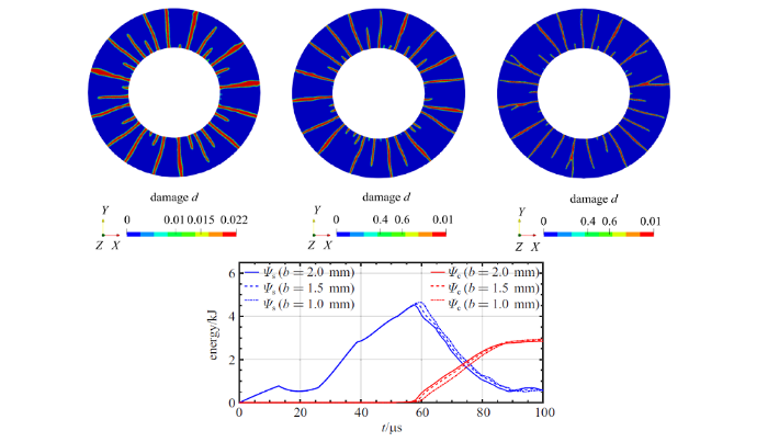
接下来考虑裂缝尺度参数的影响. 裂缝尺度参数分别取为$b=\{1.0, 1.5, 2.0 \}$ mm, 有限元网格大小均取为$h = b/5$; 总单元数分别约162万、72.3万和40.8万, 计算时间分别约为64.2 h, 31.7 h和15.1 h. 如图20所示, 由于材料随机性的影响, 数值模拟给出的裂缝路径虽然有所差异, 但碎片数量同样均为15片, 而应变能和裂缝表面能则几乎完全一样. 上述结果表明, 即便对于动力损伤破坏问题, 相场正则化内聚裂缝模型的计算结果也与裂缝尺度参数无关, 而脆性断裂相场模型 AT1/2 完全无法做到这一点[135].
图20
 新窗口打开|下载原图ZIP|生成PPT
图20厚壁圆柱动态破碎问题: 裂缝尺度参数敏感性分析[135]
Fig.20Fragmentation of a thick cylinder: Length scale sensitivity[135]
4.4 多场耦合破坏分析[140]
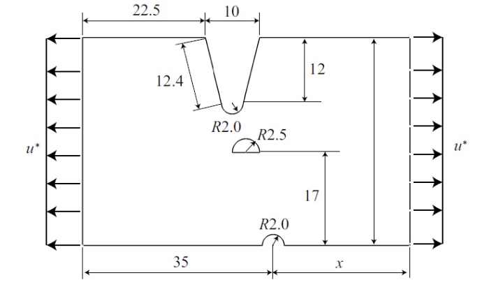
统一相场理论的控制方程是一组裂缝相场-位移场耦合的偏微分方程, 因此特别合适于多场耦合(包括力学载荷在内)条件下固体结构的破坏分析.为说明此点, 这里考虑如图21所示的金属氢脆断裂问题, 即氢离子浓度聚集会降低金属材料的破坏强度和断裂能, 加速结构损伤破坏, 这一病害在金属管道、压力容器等实际工程中经常出现.
图21
 新窗口打开|下载原图ZIP|生成PPT
图21金属氢脆腐蚀问题: 几何尺寸(单位: mm; $x = 25$ mm)、边界条件和载荷
Fig.21Hydrogen induced corrosion pits problem: Geometry (unit: mm; $x = 25$ mm), loading and boundary conditions
为了描述氢离子的影响, 引入如下耦合关系[140]
式中, $f_{{\rm t0}}$和$G_{{\rm f0}}$分别为氢离子浓度为零时材料的破坏强度和断裂能; 氢离子表面浓度$\theta$与体积浓度$C$之间满足Langmuir-McLean关系式[141], 后者则根据质量扩散方程和Fick扩散定律给出, 具体详见文献[140].
表征氢离子浓度对材料破坏强度和断裂能退化的影响函数$\phi_{1} (\theta)$和$\phi_{2} (\theta)$根据试验给出. 为简单起见, 这里假定氢离子浓度不影响材料特征长度$l_{{\rm ch}}$, 即
退化函数$\phi (\theta) = 1 - \chi \theta$, 系数$\chi$由试验或第一性原理计算得到. 材料参数由文献[142]给出: 弹性模量$E_{0} = 2.0 \times 10^{5}$ MPa, 泊松比$\nu_{0} = 0.3$, 破坏强度$f_{{\rm t0}} = 1778$ MPa, 断裂能$G_{{\rm f0}} = 90$ N/mm, 退化系数$\chi = 0.89$. 这里考虑两种氢离子稳态浓度$C = \big\{0.0, 1.0 \times10^{-6}\big\}$对结构损伤破坏的影响.
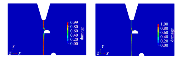
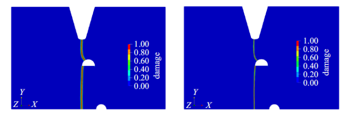
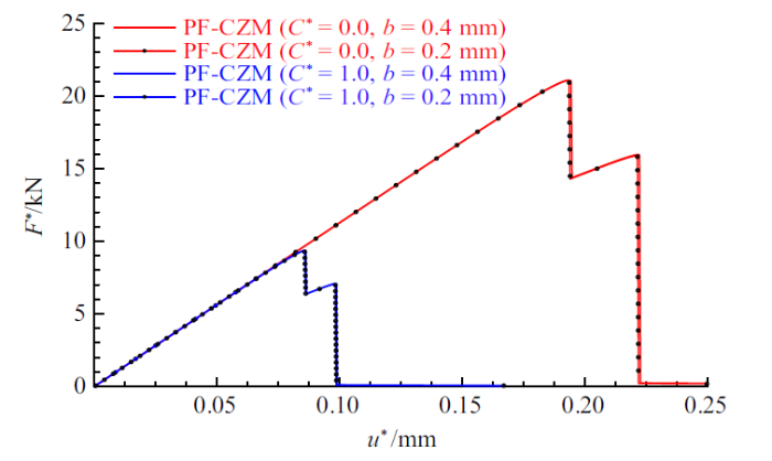
数值模拟考虑$b = \big\{ 0.4, 0.2 \big\}$ mm两种裂缝尺度参数, 相场子区域的有限元网格大小取为$h = b/5$; 总单元数分别约7万和29.5万, 计算时间分别约为4.2 h和20.7 h. 从图22和23可以看出, 由于假定氢离子浓度不改变材料的特征长度$l_{{\rm ch}}$, 两种浓度下裂缝扩展路径和结构破坏模式基本相同, 模拟给出的载荷-位移响应也基本相似, 但氢离子的存在会显著降低极限承载力(见图24). 与纯力学问题一样, 无论有无氢离子浓度的影响, 裂缝尺度参数$b$仅改变裂缝带宽度, 而不影响裂缝扩展路径、破坏模式以及载荷-位移响应等结构损伤破坏行为.
图22
 新窗口打开|下载原图ZIP|生成PPT
图22金属氢脆腐蚀问题: 裂缝尺度$b$对裂缝扩展路径的影响(氢离子浓度$C^{\ast} = 0.0$)[140]
Fig.22Hydrogen induced corrosion pits problem: Length scale analysis for the hydrogen concentration $C^{\ast} = 0.0$[140]
图23
 新窗口打开|下载原图ZIP|生成PPT
图23金属氢脆腐蚀问题: 裂缝尺度$b$对裂缝扩展路径的影响(氢离子浓度$C^{\ast} = 1.0$ $\times10^{-6}$)[140]
Fig.23Hydrogen induced corrosion pits problem: Length scale analysis for the hydrogen concentration $C^{\ast} = 1.0$ $\times10^{-6}$[140]
图24
 新窗口打开|下载原图ZIP|生成PPT
图24金属氢脆腐蚀问题: 不同裂缝尺度参数和有限元网格大小对载荷-位移曲线的影响[140]
Fig.24Hydrogen induced corrosion pits problem: Effect of the length scale parameter and mesh size on the load-displacement curves[140]
4.5 三维破坏分析[143]
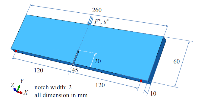
统一相场理论不受空间维度限制、无需显式表征裂缝面积并跟踪裂缝路径, 因此特别适用于非光滑、非规则裂缝扩展引起的三维结构损伤破坏问题.为此, 考虑如图25所示I+III混合型破坏的斜切口三点受弯梁问题[144-145]. 试件总长度260 mm, 跨度240 mm, 高度60 mm, 平面外厚度10 mm, $45^{\circ}$竖向斜切口的宽度和高度分别为2 mm和20 mm. 为了观测裂缝扩展过程, 试验采用透明PMMA脆性材料制作.试验发现, 随着加载位移的增大, 开始平行于斜向切口的裂缝会慢慢转动, 直至裂缝角度与梁平面垂直后继续竖直向上扩展. 这一过程中, 梁的破坏模式从平面外III型破坏逐渐转为平面内I型.
图25
 新窗口打开|下载原图ZIP|生成PPT
图25斜切口三点受弯梁I+III混合型破坏问题: 几何尺寸、边界和载荷条件
Fig.25Mixed mode I+III failure of a skewly notched beam: Geometry, loading and boundary conditions
数值模拟采用文献[146,147]给出的材料参数: 弹性模量$E_{0} = 2800$ MPa, 泊松比$\nu_{0} = 0.38$, 破坏强度$f_{\rm t} = 20$ MPa以及断裂能$G_{{\rm f}} = 0.5$ N/mm, 相应材料特征长度$l_{{\rm ch}} = 3.5$ mm. 裂缝尺度取为$b = 1.0$ mm, 相场子区域的有限元网格大小$h = 0.2$ mm; 总单元数约135万, 计算时间约为42.6 h.
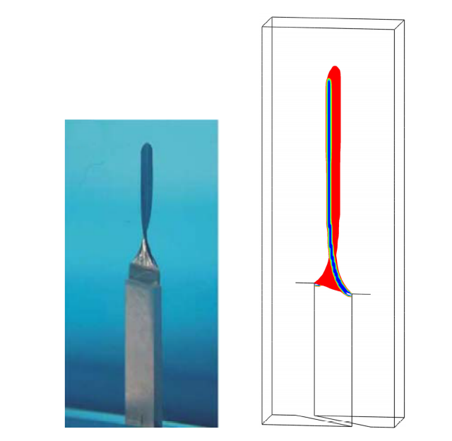
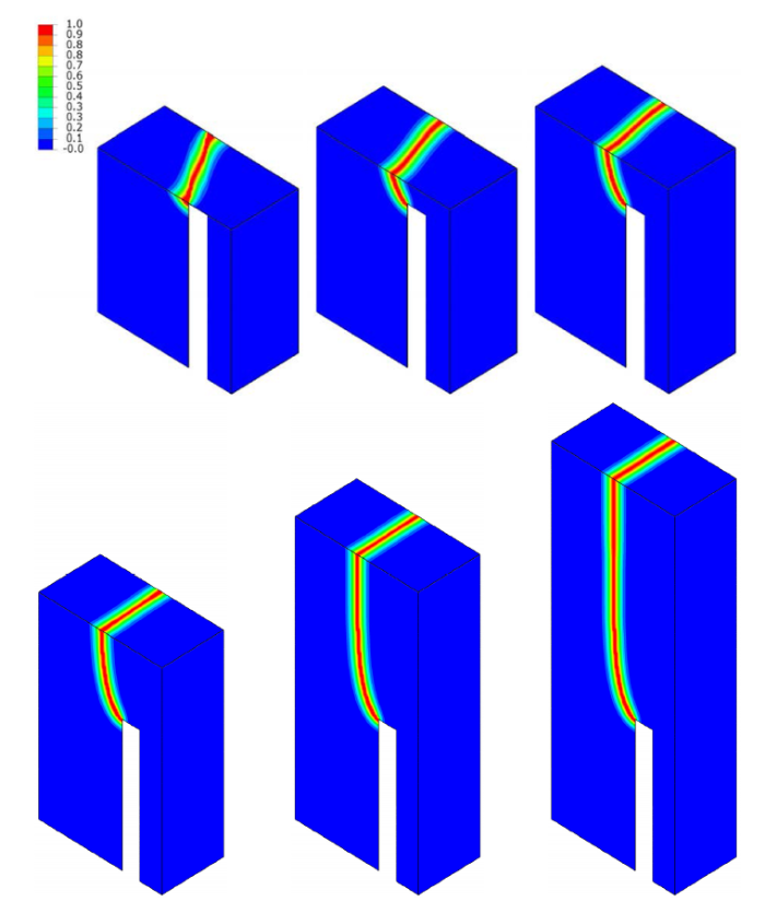
模拟给出的裂缝相场分布等值面图以及不同高度截面的裂缝相场云图分别如图26和图27所示. 可以看出, 相场正则化内聚裂缝模型能够再现试验观测到的非光滑裂缝面从斜切口处逐渐向梁顶部发生转动、然后竖直向上扩展这一复杂的损伤破坏过程.
图26
 新窗口打开|下载原图ZIP|生成PPT
图26斜切口三点受弯梁I+III混合型破坏问题: 裂缝模式对比[143]
Fig.26Mixed mode I+III failure of a skewly notched beam: Geometry, loading and boundary conditions[143]
图27
 新窗口打开|下载原图ZIP|生成PPT
图27斜切口三点受弯梁I+III混合型破坏问题: 不同截面(以斜切口处为高度基准)的裂缝相场云图[143]
Fig.27Mixed mode I+III failure of a skewly notched beam: Numerical damage profiles at various heights above the notch[143]
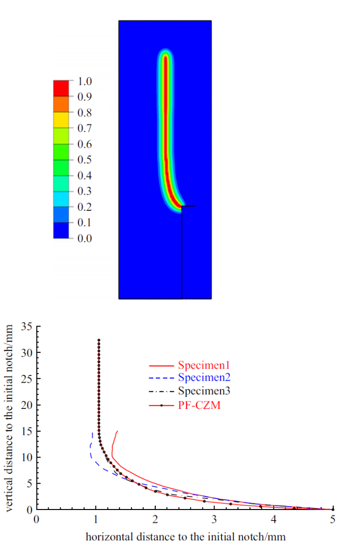
图28进一步对比了试验观测和数值模拟给出的梁侧面裂缝路径. 可以看出, 数值模拟给出的裂缝路径完全落在试验值范围内[145].
图28
 新窗口打开|下载原图ZIP|生成PPT
图28斜切口三点受弯梁I+III混合型破坏问题: 裂缝路径与试验结果对比[143]
Fig.28Mixed mode I+III failure of a skewly notched beam: Comparison of crack patterns[143]
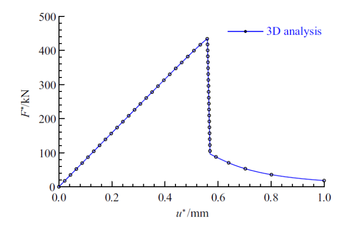
数值模拟给出的载荷-位移曲线如图29所示. 正如所预料的情况, 该梁表现出明显的弹脆性特征: 峰值载荷之前梁几乎为线弹性; 伴随着裂缝快速扩展, 载荷陡降至100 kN左右, 裂缝扩展进入稳定阶段, 承载力稳步下降, 直至最终裂缝扩展到梁顶部结构完全破坏. 上述结果表明, 相场正则化内聚裂缝模型不仅适用于准脆性材料, 同样适用于脆性材料.
图29
 新窗口打开|下载原图ZIP|生成PPT
图29斜切口三点受弯梁I+III混合型破坏问题: 载荷-位移曲线[143]
Fig.29Mixed mode I+III failure of a skewly notched beam: Load-displacement curves[143]
5 结论与展望
聚焦于固体结构损伤破坏这一世纪难题, 本文重点介绍了笔者近年来提出的统一相场理论、算法和若干应用算例.统一相场理论从裂缝的几何正则化和热力学基本原理出发, 给出了裂缝相场演化的不可逆性、能量准则和能量守恒条件, 由此建立了固体损伤破坏分析的裂缝相场-位移场耦合控制方程. 该理论将断裂力学和经典损伤力学有机结合, 同时考虑了基于强度的裂缝起裂准则、基于能量的裂缝扩展准则以及基于变分原理的裂缝扩展方向判据, 为固体材料和结构的损伤破坏分析提供了新的理论框架. 应变局部化分析表明: 裂缝尺度趋近于零时, 该理论$\varGamma$ -收敛为一类混合型的内聚裂缝模型.
将该理论应用于单轴受拉问题, 给出了相应的解析解. 特别是, 针对一组参数化的裂缝几何函数和能量退化函数, 分别得到了适用于脆性断裂和准脆性破坏的两类相场模型: 前者的宏观响应严重依赖于裂缝尺度参数, 而后者则与其无关. 在此基础上, 进一步提出了同时适用于线性软化和非线性软化的相场正则化内聚裂缝模型, 实现了脆性断裂和准脆性破坏的统一反映.
统一相场理论的裂缝相场-位移场耦合控制方程非常方便通过有限元等数值方法加以实现. 相应单元节点的自由度除节点位移外, 还包括裂缝相场自由度. 有限元空间离散后得到的非线性代数方程虽然可以采用整体牛顿迭代、子问题交错迭代以及整体BFGS拟牛顿迭代等算法进行求解, 但其性能差异明显: 虽然整体牛顿迭代算法在收敛半径内的收敛速度较快, 但由于系统能量泛函非外凸, 其数值健壮性较差; 子问题交错迭代算法虽然具有优异的收敛性, 但收敛速度极慢; 整体BFGS拟牛顿迭代方法同时具有收敛性好、收敛速度快的优点, 是目前求解裂缝相场-位移场耦合控制方程最合适的算法.
数值算例表明, 统一相场理论、特别是相场正则化内聚裂缝模型仅需少量材料力学参数(弹性模量、泊松比、抗拉强度、断裂能、软化曲线类型等), 即可直接反映静力、动力和多物理场耦合等条件下裂缝萌生、扩展、分叉等过程, 还能够有效解决三维非光滑裂缝、I/II或I/III型破坏模式转换等复杂问题. 与其他模型/方法相比, 相场正则化内聚裂缝模型消除了经典损伤力学等连续方法数值结果的网格敏感性, 还消除了非局部损伤模型错误预测裂缝起裂、裂缝带伪加载等问题; 同时, 克服了传统内聚裂缝模型网格重划分复杂繁琐、弹性罚刚度难以选取等缺点, 而且还解决了裂缝几何表征、裂缝路径跟踪、裂缝分叉准则等非连续方法(如内嵌裂缝或扩展有限元等)长期存在的难题; 此外, 相场正则化内聚裂缝不仅解决了脆性断裂相场模型存在的裂缝尺度敏感性问题, 还可广泛适用于线性软化、指数软化、混凝土科内列森软化等准脆性破坏. 归功于上述优点, 统一相场理论提出后迅速被国内外****应用于混凝土、岩石、冰、玻璃、PMMA、复合材料、橡胶等多种固体材料和结构的损伤破坏分析.
尽管统一相场理论获得了较为成功的应用, 但在以下方面仍然存在亟需进一步开展的研究工作.
(1) 考虑剪切滑移影响的相场正则化内聚裂缝模型. 通过修正有效能量释放率, 目前相场正则化内聚裂缝模型可以近似描述裂缝剪应力的影响. 然而, 单一裂缝相场变量仅能考虑I型、II型或以某种破坏形式为主的混合型破坏, 尚无法解决岩石力学或地壳断层分析中复杂的混合型破坏问题. 因此, 从固体损伤破坏的物理机理出发, 更加合理地考虑描述裂缝的法向-切向耦合行为, 进一步拓展统一相场理论的边界, 是值得深入研究的课题.
(2) 考虑裂缝扩展微惯性和微阻尼的相场动力模型. 对于动态破坏问题, 裂缝相场与位移场之间的耦合远较静力情况复杂. 现有动力相场模型大多仅考虑与位移加速度相关的宏观惯性力, 并假定宏观惯性力与裂缝相场无关, 而忽略了结构动态破坏过程中材料应变率效应的影响. 文献[81, 148-149]虽然考虑了微惯性和微阻尼对裂缝相场演化的影响, 但其参数缺乏物理机理, 导致模型模拟结果受参数取值影响极大而失去预测能力. 因此, 如何从固体动态破坏的物理机理出发, 合理地描述裂缝动态扩展过程中材料的应变率效应, 值得进一步加以探讨.
(3) 考虑亚临界状态和时间效应的相场疲劳-徐变模型. 正常使用条件下工程结构通常处于亚临界状态, 其应力水平低于材料强度. 然而, 疲劳载荷或长期载荷作用下, 工程结构仍然会出现裂缝起裂和裂缝扩展, 严重者甚至引发结构灾变破坏. 工程结构的时变损伤破坏分析一直也是结构分析的重要难点. 因此十分有必要考虑加载历史和能量累积对亚临界裂缝起裂和扩展的影响, 建立疲劳或长期加载条件下工程材料的相场疲劳-徐变模型, 并应用于工程结构的全生命周期性能分析和寿命预测.
(4) 考虑复杂多物理场耦合效应的相场分析方法. 复杂服役环境下工程结构除了受到力学载荷作用外, 往往还会遭受温度场、化学场、电磁场等多物理场耦合作用, 例如混凝土早龄期抗裂性能和高温损伤破坏分析会涉及湿-化-热-力多场耦合, 页岩气、可燃冰、地热等能源开采利用过程中也需要处理湿-热-力多场耦合问题, 电子元器件(如压电陶瓷、锂电池、半导体芯片等)研发和制造则涉及复杂的力-电耦合效应. 作为一种裂缝相场-位移场耦合分析方法, 统一相场理论在复杂多物理场耦合作用下的结构损伤破坏分析方面有着广阔的前景.
(5) 基体裂缝-界面裂缝耦合破坏的相场分析方法. 工程结构往往并非由单一材料构成, 而是由若干具有不同性能或功能的材料复合而成, 典型实例包括钢筋混凝土结构、新旧混凝土结构、FRP加固混凝土结构、高铁无砟轨道板结构、复合材料结构等. 这些工程结构破坏时, 不仅基体会出现裂缝起裂和扩展, 不同材料层间还会出现界面裂缝, 两种破坏模式相互耦合、互相竞争, 导致破坏模式具有多样性. 将相场正则化内聚裂缝模型与非连续方法联合使用, 结合两种方法各自的优点, 有望在复合材料结构损伤破坏分析方面发挥重要作用.
(6) 细观非均质材料的相场分析和材料-结构优化设计. 在细观尺度, 工程材料的非均质性不仅会直接影响到裂缝扩展路径和能量耗散, 还会对工程结构的力学性能和耗能能力产生明显影响. 将统一相场理论与X射线计算机断层扫描(XCT)方法或随机介质模型相结合, 可以分析细观非均质材料的损伤破坏行为[150]. 在此基础上, 结合拓扑优化设计方法, 对工程材料的细观结构进行优化设计和性能调控, 有望获取更高的材料强度和断裂韧性. 类似的思想也可以应用于工程结构, 对可能出现裂缝的关键区域进行局部加强或对其它非重点区域进行局部削弱, 诱导甚至主动控制裂缝路径, 实现工程结构的优化设计和性能调控.
(7) 统一相场理论的高效数值实现方法. 为了保证相场分析时裂缝面积和能量耗散的计算精度, 有限元空间离散时破坏区域内的单元网格必须足够细密, 导致整个系统的自由度数量和求解规模均较大, 即便是效率最高的整体BFGS拟牛顿迭代算法也需要耗费较多的计算时间. 因此, 采用多尺度有限元、各向异性自适应网格划分等方法降低计算量, 进一步发展更为高效的数值求解算法, 并采用GPU并行计算等方法提高计算效率, 也是将统一相场理论应用于大规模实际工程结构损伤破坏分析的重要方面.
参考文献 原文顺序
文献年度倒序
文中引用次数倒序
被引期刊影响因子
[本文引用: 1]
[本文引用: 1]
[本文引用: 1]
[本文引用: 1]
[本文引用: 1]
[本文引用: 1]
[本文引用: 1]
[本文引用: 1]
[本文引用: 1]
[本文引用: 1]
[本文引用: 1]
[本文引用: 1]
[本文引用: 1]
[本文引用: 1]
[本文引用: 2]
[本文引用: 1]
[PhD Thesis].
[本文引用: 1]
[本文引用: 1]
//
[本文引用: 1]
[本文引用: 1]
[本文引用: 1]
[本文引用: 1]
[本文引用: 3]
[本文引用: 8]
[本文引用: 1]
[本文引用: 1]
[本文引用: 1]
[本文引用: 1]
[本文引用: 1]
[本文引用: 1]
[本文引用: 1]
[本文引用: 1]
[本文引用: 9]
[本文引用: 2]
[本文引用: 3]
DOIURL [本文引用: 5]
[本文引用: 2]
[本文引用: 1]
[本文引用: 3]
[本文引用: 5]
[本文引用: 3]
[本文引用: 2]
[本文引用: 2]
[本文引用: 2]
[本文引用: 1]
[本文引用: 1]
[本文引用: 2]
[本文引用: 1]
[本文引用: 1]
[本文引用: 1]
[本文引用: 3]
[本文引用: 3]
[本文引用: 1]
[本文引用: 2]
[本文引用: 1]
[本文引用: 1]
[本文引用: 17]
[本文引用: 3]
[本文引用: 13]
URL [本文引用: 11]
[本文引用: 7]
[本文引用: 2]
[本文引用: 5]
[本文引用: 2]
[本文引用: 2]
DOIURLPMID [本文引用: 3]

Despite their seemingly delicate appearance, thin biological membranes fulfill various crucial roles in the human body and can sustain substantial mechanical loads. Unlike engineering structures, biological membranes are able to grow and adapt to changes in their mechanical environment. Finite element modeling of biological growth holds the potential to better understand the interplay of membrane form and function and to reliably predict the effects of disease or medical intervention. However, standard continuum elements typically fail to represent thin biological membranes efficiently, accurately, and robustly. Moreover, continuum models are typically cumbersome to generate from surface-based medical imaging data. Here we propose a computational model for finite membrane growth using a classical midsurface representation compatible with standard shell elements. By assuming elastic incompressibility and membrane-only growth, the model a priori satisfies the zero-normal stress condition. To demonstrate its modular nature, we implement the membrane growth model into the general-purpose non-linear finite element package Abaqus/Standard using the concept of user subroutines. To probe efficiently and robustness, we simulate selected benchmark examples of growing biological membranes under different loading conditions. To demonstrate the clinical potential, we simulate the functional adaptation of a heart valve leaflet in ischemic cardiomyopathy. We believe that our novel approach will be widely applicable to simulate the adaptive chronic growth of thin biological structures including skin membranes, mucous membranes, fetal membranes, tympanic membranes, corneoscleral membranes, and heart valve membranes. Ultimately, our model can be used to identify diseased states, predict disease evolution, and guide the design of interventional or pharmaceutic therapies to arrest or revert disease progression.
[本文引用: 3]
[本文引用: 2]
[本文引用: 2]
[本文引用: 2]
[本文引用: 3]
[本文引用: 3]
[本文引用: 1]
DOIURL [本文引用: 2]
DOIURLPMID [本文引用: 1]
Modeling of drug transport within capillaries and tissue remains a challenge, especially in tumors and cancers where the capillary network exhibits extremely irregular geometry. Recently introduced Composite Smeared Finite Element (CSFE) provides a new methodology of modeling complex convective and diffusive transport in the capillary-tissue system. The basic idea in the formulation of CSFE is in dividing the FE into capillary and tissue domain, coupled by 1D connectivity elements at each node. Mass transport in capillaries is smeared into continuous fields of pressure and concentration by introducing the corresponding Darcy and diffusion tensors. Despite theoretically correct foundation, there are still differences in the overall mass transport to (and from) tissue when comparing smeared model and a true 3D model. The differences arise from the fact that the smeared model cannot take into account the detailed non-uniform pressure and concentration distribution in the vicinity of capillaries. We introduced a field of correction function for diffusivity through the capillary walls of smeared models, in order to have the same mass accumulation in tissue as in case of true 3D models. The parameters of the numerically determined correction function are: ratio of thickness and diameter of capillary wall, ratio of diffusion coefficient in capillary wall and surrounding tissue; and volume fraction of capillaries within tissue domain. Partitioning at the capillary wall - blood interface can also be included. It was shown that the correction function is applicable to complex configurations of capillary networks, providing improved accuracy of our robust smeared models in computer simulations of real transport problems, such as in tumors or human organs.
[本文引用: 1]
[本文引用: 1]
[本文引用: 1]
DOIURL [本文引用: 1]
[本文引用: 5]
[本文引用: 1]
[本文引用: 2]
[本文引用: 1]
[本文引用: 1]
[本文引用: 3]
[本文引用: 3]
[本文引用: 1]
[本文引用: 1]
DOIURL
DOIURLPMID [本文引用: 1]
The production of fuels from sunlight represents one of the main challenges in the development of a sustainable energy system. Hydrogen is the simplest fuel to produce and although platinum and other noble metals are efficient catalysts for photoelectrochemical hydrogen evolution, earth-abundant alternatives are needed for large-scale use. We show that bioinspired molecular clusters based on molybdenum and sulphur evolve hydrogen at rates comparable to that of platinum. The incomplete cubane-like clusters (Mo(3)S(4)) efficiently catalyse the evolution of hydrogen when coupled to a p-type Si semiconductor that harvests red photons in the solar spectrum. The current densities at the reversible potential match the requirement of a photoelectrochemical hydrogen production system with a solar-to-hydrogen efficiency in excess of 10%. The experimental observations are supported by density functional theory calculations of the Mo(3)S(4) clusters adsorbed on the hydrogen-terminated Si(100) surface, providing insights into the nature of the active site.
[本文引用: 1]
[本文引用: 1]
[本文引用: 1]
[本文引用: 2]
[本文引用: 1]
DOIURL [本文引用: 9]
DOIURL [本文引用: 1]
[本文引用: 1]
DOIURL [本文引用: 1]
In the modeling of pressurized fractures using phase-field approaches, the irreversibility of crack growth is enforced through an inequality constraint on the temporal derivative of the phase-field function. In comparison to the classical case in elasticity, the presence of the pressure requires the additional constraint and makes the problem much harder to analyze. After temporal discretization, this induces a minimization problem in each time step over a solution dependent admissible set. To avoid solving the resulting variational inequality corresponding to the first order necessary conditions, a penalization approach is used, commonly, to remove the inequality constraint. It is well-known that for large penalty parameters the algorithm suffers from numerical instabilities in the solution process. Consequently, to avoid such a drawback, we propose an augmented Lagrangian algorithm for the discrete in time and continuous in space phase-field problems. The final set of equations is solved in a decoupled fashion. The proposed method is substantiated with several benchmark and prototype tests in two and three dimensions. (C) 2013 Elsevier B.V.
[本文引用: 1]
[本文引用: 1]
DOIURL [本文引用: 3]
DOIURL [本文引用: 1]
URLPMID [本文引用: 2]
[本文引用: 1]
[本文引用: 3]
[本文引用: 2]
[本文引用: 3]
[本文引用: 1]
[本文引用: 1]
[本文引用: 2]
[本文引用: 1]
[本文引用: 1]
[本文引用: 2]
[本文引用: 1]
[本文引用: 1]
DOIURL [本文引用: 1]
DOIURL [本文引用: 1]
[本文引用: 1]
DOIURL [本文引用: 1]
[本文引用: 1]
[本文引用: 1]
DOIURL [本文引用: 1]
[本文引用: 2]
[本文引用: 1]
[本文引用: 1]
[本文引用: 4]
[本文引用: 1]
[本文引用: 2]
[本文引用: 8]
[本文引用: 1]
[本文引用: 2]
[本文引用: 1]
[本文引用: 1]
[本文引用: 9]
[本文引用: 1]
[本文引用: 1]
[本文引用: 10]
DOIURL [本文引用: 1]
[本文引用: 2]
[本文引用: 1]
[本文引用: 1]
[本文引用: 1]
DOIURL [本文引用: 1]
[本文引用: 1]
