 ,2), 侯冬杨, 高诚辉福州大学 机械工程及自动化学院, 福州 350116
STUDY ON FRACTURE TOUGHNESS OF SEMICONDUCTOR MATERIAL USING VICKERS AND BERKOVICH INDENTERS1)
Liu Ming,2), Hou Dongyang, Gao ChenghuiSchool of Mechanical Engineering and Automation, Fuzhou University, Fuzhou 350116, China通讯作者: 2) 刘明, 教授, 主要研究方向: 表面微观力学与压痕测试方法. E-mail:mingliu@fzu.edu.cn
收稿日期:2020-10-7接受日期:2021-01-9网络出版日期:2021-02-07
| 基金资助: |
Received:2020-10-7Accepted:2021-01-9Online:2021-02-07
作者简介 About authors

摘要
压痕法是测量材料断裂韧性 ($K_{\rm IC})$ 的常用方法之一, 如何根据不同的材料、不同的压头选择适合的公式, 是当前面临的一大问题. 因此,在不同载荷下对单晶硅 (111) 和碳化硅 (4H-SiC, 0001面) 这两种半导体材料进行了维氏微米硬度和玻氏纳米压痕实验, 对实验产生的裂纹长度$c$进行了统计分析, 并采用13个压痕公式计算材料的$K_{\rm IC}$, 开展了微米划痕实验, 验证压痕法评估半导体材料$K_{\rm IC}$的适用性. 研究结果表明: 为了消除维氏压痕实验产生的$c$的固有离散性, 需要多次测量取平均值; 裂纹长度与压痕尺寸的比值随压痕载荷的增大而增大; 材料的裂纹类型与载荷相关且低载荷下表现为巴氏裂纹, 高载荷下表现为中位裂纹; 与微米划痕实验得到的单晶硅和碳化硅材料的$K_{\rm IC}$平均值 (分别为0.96 MPa,$\cdot$,$\sqrt{\rm m}$和2.89 MPa,$\cdot$,$\sqrt{\rm m}$) 相比, 在同一压头下无法从13个公式中获得同时适用于单晶硅和碳化硅材料的压痕公式,但在同一材料下可以获得同时适用于维氏和玻氏压头的$K_{\rm IC}$计算公式; 基于中位裂纹系统发展而来的压痕公式更适合用于评估半导体材料的$K_{\rm IC}$, 且维氏压头下的$K_{\rm IC}$与玻氏压头下$K_{\rm IC}$的关系不是理论上的1.073倍, 应为1.13$\pm $0.01.}
关键词:
Abstract
The indentation method is one of the commonly used methods to determine fracture toughness ($K_{\rm IC})$ of brittle materials. One of the challenges is to obtain a suitable equation of the materials from various equations according to different materials and indenters. Therefore, fracture toughness tests with pyramid indenters (Vickers indenter and Berkovich indenter) were conducted on Si (111) and 4H-SiC (0001) under various loads. The crack length $c$ generated in the Vickers indentation experiments were statistically analyzed, and thirteen equations were selected to calculate the fracture toughness of semiconductor materials at room temperature. The applicability of the indentation test was evaluated, based on a comparative analysis with the results of the scratch test. The results show that to eliminate the inherent discreteness of crack length $c$ generated in the Vickers indentation experiment, multiple indentation tests (at least thirty tests) need to be conducted. The ratio of crack length $c$ over the indentation diagonal length $a$ increases with an increase in the applied load $P$. The crack types of the materials depend on $P$: Palmqvist crack system appears for low loads and Median crack system appears for high loads. Compared with the average fracture toughness (0.96~MPa,$\cdot$,$\sqrt{\rm m}$ and 2.89~MPa,$\cdot$,$\sqrt{\rm m}$, respectively) of Si (111) and 4H-SiC (0001) obtained by micro scratch test, based on linear elastic fracture mechanics (LEFM), the appropriate equations was obtained for both Vickers and Berkovich indenters for the same as material, but which can not be obtained for both Si (111) and 4H-SiC (0001) under the same as indenter from thirteen equations. The fracture toughness of semiconductor materials are best calculated by an expression develope from the Median crack system, and the relationship between fracture toughness being obtained with Vickers indenter and that of with Berkovich indenter is not theoretically 1.073 times, which should be 1.13$\pm $0.01.
Keywords:
PDF (4619KB)元数据多维度评价相关文章导出EndNote|Ris|Bibtex收藏本文
本文引用格式
刘明, 侯冬杨, 高诚辉. 利用维氏和玻氏压头表征半导体材料断裂韧性1). 力学学报[J], 2021, 53(2): 413-423 DOI:10.6052/0459-1879-20-349
Liu Ming, Hou Dongyang, Gao Chenghui.
引言
断裂韧性是指材料抵抗裂纹扩展的能力[1], 通常用临界应力强度因子$K_{\rm IC}$作为衡量指标, 单位为MPa $\cdot$ $\sqrt{\rm m}$. 字母$K$为应力场强度因子, 反映的是裂纹尖端区域应力场强弱; 字母C指的是裂纹扩展的临界情况; 下标罗马数字I是指裂纹扩展形式为张开型, 脆性材料的裂纹扩展类型即为I型. 研究材料的$K_{\rm IC}$可以用来评估典型工程结构(例如石化容器和储罐、石油和天然气管道以及汽车、船舶和飞机结构[2]) 的材料性能以及用来确定脆性材料 (如石英玻璃) 的微观参数[3].目前, 测量材料$K_{\rm IC}$的方法主要有: 山形切口梁法 (CNB)[4-5]、单边预裂梁法 (SEPB)[4-5]、表面弯曲裂纹法 (SCF)[4]、单边切口梁法 (SENB)[4-5]、单边V形切口梁法 (SEVNB)[5]、短V形切口杆法(SR)[5]、双扭法(DT)[4-5]、双悬臂梁法(DCB)[4-5]、微米划 痕法[6-8]、压痕 法(如纳米压痕法[9-10]和维氏压痕法[11-12])等. SR, DCB和SEPB法的测试试样难生产、成本高, 故无法得到广泛使用; SENB, SEVNB和CNB法加工试样缺口较为困难; DT法试件的几何尺寸会对测量值产生影响; SCF法必须要去除足够深度的表面层来消除残余应力场, 才能保证$K_{\rm IC}$不被高估[4-5]; 微米划痕法需要考虑压头的磨损以确保测试结果的准确性[13]; 而压痕法具有制备试样简单、测试效率高、以及综合成本低等优点, 已被广泛地应用于陶瓷材料[14-15]、硬质合金[16-17]和玻璃材料[18-19]的硬度、弹性模量和韧性测量.
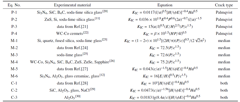
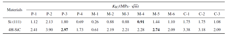
最初, Lawn等[11]在1980年基于弹-塑性断裂力学提出了计算$K_{\rm IC}$的公式 (称为LEM模型). 随后, Anstis等[12]使用了许多较大$K_{\rm IC}$范围 (0.74 $\sim$ 12 MPa $\cdot$ $\sqrt{\rm m}$) 的参考材料, 得出了公式中的无量纲常数$\chi =0.016\pm 0.004$. 基于Lawn等[11]和Anstis等[12]的研究, 研究者们提出了许多确定$K_{\rm IC}$的公式[20-30], 见表1. 这些公式主要是考虑两种不同的裂纹类型得到的, 一种是基于半椭圆型的巴氏裂纹 (Palmqvist crack); 另一种是基于半月状的中位裂纹 (median crack), 而第三种是基于曲线拟合方法得到的, 同时适用于两种裂纹系统.
Table 1
表1
表1利用维氏硬度法计算材料断裂韧性的方程
Table 1
 |
新窗口打开|下载CSV
近年来, 使用压痕法确定$K_{\rm IC}$的有效性引起了激烈的争论. 文献[31,32]认为, 计算$K_{\rm IC}$的公式在实际应用中有许多的限制或问题, 例如裂纹系统 (径向、中位、横向等) 的多样性引起的复杂性, 压头下方应力场的不确定性以及有时会得到不可靠的$K_{\rm IC}$计算结果. 因此, 对于陶瓷材料的断裂韧性测试, 压痕法不建议被使用. 然而, Marshall等[33]认为压痕法是基于Griffith-Irwin平衡断裂力学得到的, 并且压痕是反映材料机械性能独一无二的特征, 因此, 压痕法仍然是有效的方法. 但是, 使用压痕法评估材料的$K_{\rm IC}$仍然存在许多不足 (如对低泊松比的材料并不适用[34]), 如何根据不同的材料、不同的压头选择适合的公式, 成为当前压痕法在实际应用中需要解决的困难之一.
单晶硅作为一种性能优越的半导体材料, 现已被广泛应用于芯片、光学元件和太阳电池[35]等领域的加工制造. 碳化硅作为第三代半导体材料, 由于其具有更大的禁带宽度, 非常适合用于制造5G射频器件和高电压功率器件[36], 裂纹扩展进而引起的脆性断裂是其主要失效形式之一[37-39]. 在一般工程构件中, 这些材料发生脆断前并没有明显的塑性变形, 而断裂韧性可以很好地衡量这种特性.本工作基于单晶硅 (111) 和碳化硅 (4H-SiC) 维氏微米硬度和玻氏纳米压痕实验$K_{\rm IC}$测试结果, 与划痕实验测试结果进行比对分析后, 讨论了使用表1总结的13个压痕公式评估半导体材料$K_{\rm IC}$的适用性, 并希望获得有效的压痕实验条件和特定压头下材料的适用公式, 以期为压痕法表征半导体材料的断裂韧性提供参考.
图1
 新窗口打开|下载原图ZIP|生成PPT
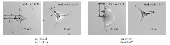
图1单晶硅和碳化硅维氏和玻氏压痕的光学图片
Fig.1Optical micrographs of the Vickers and Berkovich indentation for Si (111) and 4H-SiC
1 实验材料与步骤
1.1 实验材料
实验压痕试样涉及两种半导体材料, 单晶硅 (111) 和碳化硅 (4H-SiC, 0001面), 试样尺寸为块体, 满足平面应变条件. 实验之前对试样表面进行多级水磨, 并通过机械抛光去除表面划痕直到达到镜面效果, 然后在无水乙醇中对试样进行超声波清洗, 以清除试样表面残留的研磨颗粒等杂质, 材料的弹性模量和泊松比见表2.Table 2
表2
表2样品参数和维氏压痕尺寸
Table 2
 |
新窗口打开|下载CSV
1.2 实验步骤
1.2.1 压痕实验维氏压痕实验使用数显硬度计 (MHVKD-100, 上海钜晶仪器制造有限公司) 将维氏压头按确定的 载荷垂直压入样品表面, 保载15 s. 为提高测量结果的可靠性和重复性, 在不同载荷下, 对同一种材料进行测试的数量为30次. 玻氏压痕实验使用纳米压痕仪(型号NHT$^{2}$, Anton Paar公司) 在力控制模式下将压头垂直压入样品表面[43]. 实验的压痕形貌图如图1所示.
1.2.2 划痕实验
使用微米划痕仪 (型号MST$^{2}$, Anton Paar公司) 在渐进加载模式下利用半径为$R=100$ $\mu$m的Rockwell压头进行划痕实验[13]. 单晶硅和碳化硅最大加载载荷分别为6 N和10 N, 划痕速率和长度均为4 mm/min和2 mm.
2 结果与讨论
2.1 维氏压头下裂纹长度$c$的讨论
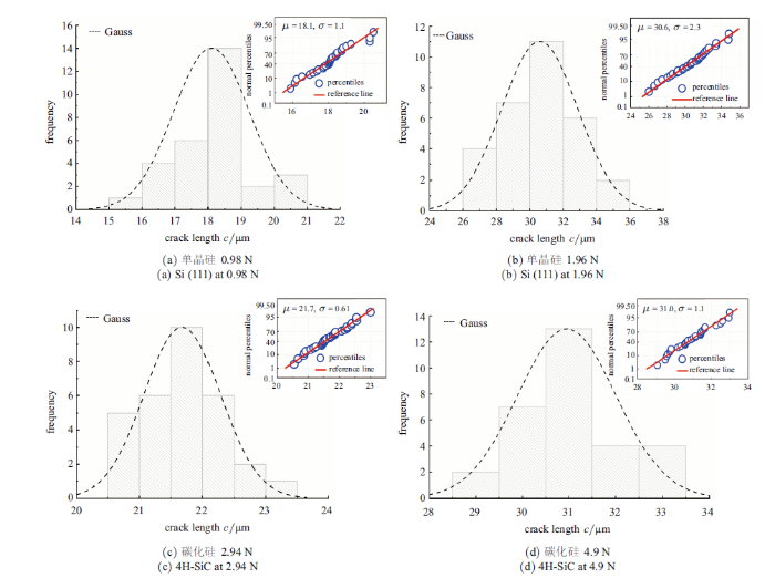
图2给出了维氏压头下单晶硅在载荷0.98 N和1.96 N、碳化硅在载荷2.94 N和4.90 N时$c$的经验概率密度函数图, 其中虚线是使用高斯 (Gauss) 拟合得到的. 单晶硅在0.98 N和1.96 N载荷下$c$的范围分别分布在15 $\sim$ 21 $\mu$m和26 $\sim$ 35 $\mu$m之间, 最大值均约为最小值的1.4倍, 对于碳化硅而言是1.2倍且数值分布都较为离散, 这说明对$c$进行统计分析是十分有意义的, 说明$c$的测量数据服从高斯分布. 对于单晶硅和碳化硅材料的其他载荷下也可以得到相同的结论. 表2列出了维氏压头下材料在不同载荷下$c$的平均值$c_{\rm A}$和正态统计分析值$c_{\rm G}$, 结果表明, 两者几乎相同, 说明在较大样本量 (压痕测试次数为30次) 的情况下, 对$c$取平均值的处理方法是合理的, 这与Gong等[44]的表述相吻合.图2
 新窗口打开|下载原图ZIP|生成PPT
图2维氏压头下Si (111)和4H-SiC材料裂纹长度$c$的概率密度函数图和正态性检验图
Fig.2Probability density function diagram and normal inspection diagram of crack length $c$ of Si (111) and 4H-SiC under Vickers indenter
2.2 单晶硅和碳化硅材料压痕硬度的讨论
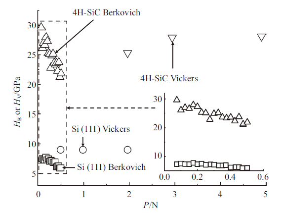
图3是材料的纳米压痕硬度 ($H_{\rm B})$ 与维氏硬度($H_{\rm V})$ 随载荷的变化图, 需要注意的是, 这里硬度的定义均是载荷与残余压痕面积的比值, 而不是载荷与投影面积的比值. 结果表明, 在玻氏压头下, 随着载荷的增大, 材料的压痕硬度整体表现出下降的趋势, 表现出压痕尺寸效应 (ISE)[45]. 碳化硅材料在较小区间内会出现硬度略微上升的现象 (见图中箭头指向), 维氏压头下也有相同现象产生, 微小上升的原因归因于表面形貌的影响或测量带来的误差. 研究发现, 单晶硅的$H_{\rm V}$在0.49 N, 0.98 N和1.96 N时均为9 GPa, 与Lawn等[11]的测试结果(9 GPa) 一致; 碳化硅的$H_{\rm V}$在1.96 N, 2.94 N 和4.90 N时分别为25.3 GPa, 27.9 GPa和28.1 GPa, 与文献[46]的测试结果相接近.图3
 新窗口打开|下载原图ZIP|生成PPT
图3样品的维氏和纳米硬度随载荷的变化图
Fig.3Variation of hardness with the load under Vickers and Berkovich indenter
2.3 单晶硅和碳化硅材料裂纹系统的讨论
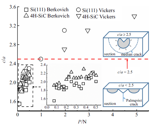
由于计算材料$K_{\rm IC}$所使用的压痕公式建立在不同的裂纹系统的基础上, 有必要对其裂纹类型进行识别. 图4给出了两种实验材料的$c/a$值随载荷的变化图 (图中还包含了两种裂纹系统模型图). 研究发现, 材料的$c$/$a$值随着压痕载荷$P$的增大而增大. 在玻氏压头下, 单晶硅和碳化硅材料的$c$/$a$值均小于2.5, 根据经验判据(若$c/a<2.5$, 材料表现为巴氏裂纹系统; 若$c/a\geqslant 2.5$, 则表现为中位裂纹系统), 均表现为巴氏裂纹系统. 在维氏压头下, 碳化硅在测试载荷下均表现为中位裂纹系统, 而单晶硅的裂纹系统与载荷有关, 在0.49 N时表现为巴氏裂纹系统, 在0.98 N和1.96 N时则表现为中位裂纹系统. 结果表明, 如果不考虑压头形状对裂纹类型的影响, 材料的裂纹类型则取决于实验施加的载荷, 在低载荷下表现为巴氏裂纹, 在高载荷下表现为中位裂纹, 这与文献[47,48]的结论相吻合.图4
 新窗口打开|下载原图ZIP|生成PPT
图4样品的$c/a$值及巴氏和中位裂纹模型
Fig.4$c/a$ of samples and model of Palmqvist and Median crack
2.4 单晶硅和碳化硅材料断裂韧性的讨论
由于测试试样尺寸较小, 无法使用常规宏观测试方法测量其$K_{\rm IC}$, 这里是通过与划痕实验$K_{\rm IC}$测试 结果进行比较分析, 并依此来评价各种压痕经验公式的适用性. 根据线弹性断裂力学 (LEFM) 理论, 微米划痕法计算材料$K_{\rm IC}$的公式为[49-50]式中$F_{\rm t}$为切向力, 单位为mN; $p$和$A$分别为压头与试样接触部分的投影周长和投影面积, 单位分别为$\mu$m和$\mu$m$^{2}$.
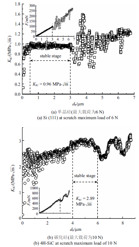
图5(a)和图5(b)分别为单晶硅和碳化硅材料基于LEFM模型求解的$K_{\rm IC}$随压入深度$d_{\rm p}$的变化图. $K_{\rm IC}$随$d_{\rm p}$的增大而增大, 随后趋于稳定, 之后发生剧烈波动. $K_{\rm IC}$在$d_{\rm p}$较大时发生剧烈波动的原因是由于在大载荷下材料发生严重地脆性破坏, 并在压头下方产生碎屑导致$F_{t}$的测量值不稳定, 如图5插图所示. 另外, 由于LEFM 模型是在材料达到裂纹失稳的状况下建立的, 即其在较大载荷下才能反映出材料的真实断裂韧性值, 因此, 取$K_{\rm IC}$-$d_{\rm p}$曲线稳定段的平均值作为单晶硅和碳化硅材料基于LEFM模型的计算结果. 单晶硅在$K_{\rm IC}$-$d_{\rm p}$曲线稳定段的平均值为0.96 MPa $\cdot$ $\sqrt{\rm m}$, 与四点弯曲法[51] (0.91 MPa $\cdot$ $\sqrt{\rm m}$) 的测试结果接近. 碳化硅的平均值为2.89 MPa $\cdot$ $\sqrt{\rm m}$, 与DT法[26] (3.1 MPa $\cdot$ $\sqrt{\rm m}$) 的测试结果基本一致, 说明LEFM模型能够很好地表征半导体材料的$K_{\rm IC}$.
图5
 新窗口打开|下载原图ZIP|生成PPT
图5基于LEFM模型的断裂韧性分析
Fig.5Fracture toughness analysis based on LEFM model
2.4.1 维氏压头下材料断裂韧性的讨论
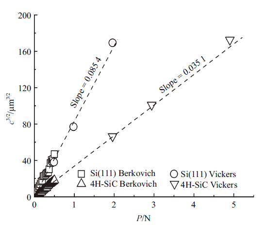
图6给出了维氏和玻氏压头下载荷$P$与$c^{3/2}$之间关系的检查结果, 表明单晶硅和碳化硅材料的载荷$P$与$c^{3/2}$之间呈线性关系. 两种材料断裂韧性的不同导致了对应直线斜率的差异, 且韧性大的材料斜率小, 韧性小的材料斜率大.
图6
 新窗口打开|下载原图ZIP|生成PPT
图6维氏和玻氏压头下载荷$P$与$c^{3/2}$的关系图
Fig.6Plots of $c^{3/2}$ versus load under Vickers and Berkovich indenters
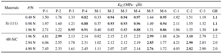
表3给出了材料在维氏压头下使用表1公式计算得到的$K_{\rm IC}$数据. 结果表明, 使用不同公式计算出来的$K_{\rm IC}$相差较大, 因为这些公式都是由实验得到的经验方程, 适用于不同的材料, 所以, 如果在计算$K_{\rm IC}$时选择了不适用的公式, 则可能产生较大的误差. 在不同载荷下, 使用同一公式计算出来的$K_{\rm IC}$也有明显差异. 因此, 选择出适合材料的压痕公式十分重要. 研究发现, 对于单晶硅而言, 在1.96 N载荷下, 使用 P-3 公式计算得到的$K_{\rm IC}$与划痕实验测试结果一致; P-4 公式的计算结果随载荷的增大而增大, 而在大载荷下单晶硅材料会发生严重地脆性破坏, $K_{\rm IC}$会被低估, 故 P-3 和 P-4 公式并不适合被用于评估单晶硅材料的$K_{\rm IC}$. 在所有测试载荷下, M-2, M-3, M-4 和 M-6 公式的计算结果与划痕实验测试结果相接近, 但在0.49 N和0.98 N载荷下, M-4 公式的计算结果与划痕实验结果几乎一致. 因此, 在维氏压头下使用 M-4 公式评估单晶硅材料的$K_{\rm IC}$时建议使用此载荷条件. 另外, M-2, M-3 和 M-4 公式的计算结果相一致, 这是因为 M-3 和 M-4 公式是在经典的 Evans-Charles 方程——M-2 公式上进行修正和演化而来的, 它们的表达式形式相似, 只是系数略有不相同. 对于碳化硅, 尽管 P-2 公式的计算结果与划痕实验结果一致, 但其仅在1.96 N载荷下适用, 在测试载荷内的稳定性较差, 故认为其不适用于评估碳化硅材料的$K_{\rm IC}$. 在所有测试载荷下, M-5 和 C-2 公式的计算结果与划痕结果接近, 但在2.94 N的载荷下, 结果更加准确. 因此, 使用 M-5 和 C-2 公式评估碳化硅材料的$K_{\rm IC}$时建议使用2.94 N的压痕载荷.
Table 3
表3
表3维氏压头下单晶硅和碳化硅的$K_{\rm IC}$计算值
Table 3
 |
新窗口打开|下载CSV
2.4.2 玻氏压头下材料断裂韧性的讨论
表1中的13个压痕公式是基于维氏压头发展出的半经验公式, 不能直接应用于具有非对称的玻氏压头[43]. 因此, Ouchterlony[52]发展出了一个修正因子$f(n)$以说明从承受中心膨胀力的载荷点发出的裂纹数量对$K_{\rm IC}$的影响.
式中$n$为裂纹数量, 且$n \leqslant 9$时, 维氏压头与玻氏压头的断裂韧性满足一次函数的关系[53]. 因此, 在玻氏压头下使用表1公式计算材料$K_{\rm IC}$时, 需在公式前乘以修正系数$k_{\rm B} =f(4)/f(3)=1.073$.
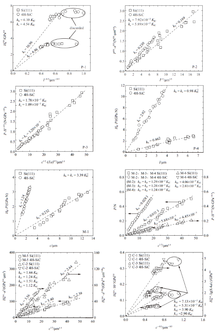
图7给出了在玻氏压头下计算材料$K_{\rm IC}$的示意图. 通过拟合出在不同载荷下表1压痕公式中各参数之间的线性关系, 得到两种材料拟合直线的斜率$k_{h}$ (Si) 和$k_{s}$ (4H-SiC), 根据$k_{h}$和$k_{s}$与$K_{\rm IC}$的等式关系 (对13个压痕公式进行形式变换得到的) 即可求出材料的$K_{\rm IC}$. 这里需要注意的是, 图7(a)和图7(h)中圈出的部分分别是材料在0.2 N和0.125 N以下得到的数据点, 均出现了偏离线性关系的现象, 表明在小载荷下不适合使用 P-1, C-1 和 C-3 公式评估材料的$K_{\rm IC}$, 因而在拟合直线时这些点将被丢弃, 这说明压痕公式都有其局限及适用范围. 使用适用超薄玻璃的GB/T 37900—2019[54]中的压痕公式计算了两种实验材料的$K_{\rm IC}$. 结果表明, GB/T 37900—2019[51]可以用来评估单晶硅材料的$K_{\rm IC}$, 但对于碳化硅不适用, 验证了上面的结论 (见表3中GB列).
图7
 新窗口打开|下载原图ZIP|生成PPT
图7玻氏压头下计算材料$K_{\rm IC}$的示意图
Fig.7Schematic diagram of calculating fracture toughness of materials under Berkovich indenter
表4给出了玻氏压头下材料的$K_{\rm IC}$测量结果. 表明, 对于单晶硅而言, 使用 M-2、M-3 和 M-4 公式计算出的$K_{\rm IC}$与划痕实验测试结果相接近, 但 M-4公式的计算结果更加准确. 对于碳化硅而言, 适用的公式是 P-3 和 M-5. 研究发现, 在玻氏压头下, 除 P-3 公式外, 其他适用公式的$K_{\rm IC}$计算结果明显小于划痕实验测试结果, 说明利用玻氏压头评估半导体材料$K_{\rm IC}$时, 在表1中的维氏压痕公式的基础上乘以一个理论修正系数1.073不足以获得准确的$K_{\rm IC}$结果, 需要对其进行校正, 校正后的修正系数$k_{\rm B}$见表5. 结果表明, 利用玻氏压头评估半导体材料的$K_{\rm IC}$时的压痕公式的修正系数应为1.13$\pm $0.01.
Table 4
表4
表4玻氏压头下单晶硅和碳化硅材料的$K_{\rm IC}$计算值
Table 4
 |
新窗口打开|下载CSV
Table 5
表5
表5利用玻氏压头评估单晶硅和碳化硅材料$K_{\rm IC}$时适用公式的修正系数$k_{\rm B}$
Table 5
 |
新窗口打开|下载CSV
对比表3和表4的$K_{\rm IC}$测量结果, 发现适用于中位裂纹系统的压痕公式更适合评估半导体材料的$K_{\rm IC}$, 且没有一个公式可以同时适用于单晶硅和碳化硅材料, 但对于同一材料, 可以获得同时适用于两种压头的$K_{\rm IC}$计算公式. 对于单晶硅而言,
两种压头的共同适用公式是 M-4, 对于碳化硅而言, 是 M-5 公式.
3 结论
本工作通过对Si (111) 和4H-SiC (0001) 开展维氏微米硬度和玻氏纳米压痕实验, 讨论了材料在维氏压头下产生的裂纹长度的特点, 使用13个压痕公式计算出了材料的断裂韧性并与划痕实验测量结果进行了比对分析, 验证了压痕法评估半导体材料断裂韧性的适用性. 根据实验结果和上面的讨论, 可以得出以下结论.(1) 由于在维氏压痕实验中产生的裂纹长度分布较为离散, 有必要对其进行统计分析. 结果表明, 在大样本量 (压痕次数为30次) 下, 可以对裂纹长度进行取平均值的处理.
(2) 利用维氏压头评估半导体材料断裂韧性时, 单晶硅的建议载荷是0.49 N和0.98 N, 碳化硅是2.94 N. 在玻氏压头下, 可以通过拟合不同力下压痕公式各参数之间的线性关系来求解半导体材料的断裂韧性.
(3) 压痕公式都有其局限及适用范围. 对于单晶硅而言, 两种压头的共同适用公式是 M-4, 对于碳化硅而言, 是 M-5 公式.
参考文献 原文顺序
文献年度倒序
文中引用次数倒序
被引期刊影响因子
[硕士论文].
[本文引用: 1]
[Master Thesis].
[本文引用: 1]
[本文引用: 1]
[本文引用: 1]
[本文引用: 1]
[本文引用: 7]
[本文引用: 8]
[本文引用: 1]
[本文引用: 1]
[本文引用: 1]
[本文引用: 1]
[本文引用: 4]
[本文引用: 3]
[本文引用: 2]
[本文引用: 2]
[本文引用: 1]
[本文引用: 1]
[本文引用: 1]
[本文引用: 1]
[本文引用: 1]
[本文引用: 1]
[本文引用: 1]
[本文引用: 1]
[本文引用: 1]
[本文引用: 1]
[本文引用: 1]
DOIURLPMID

Composites filled with a silicate glass (CSi) and a new borate glass (CB) were developed and compared in terms of their in vitro behaviour both in acellular and cellular media. Acellular tests were carried out in SBF and the composites were characterized by SEM-EDS, XRD and ICP. Biocompatibility studies were investigated by in vitro cell culture with MG-63 osteoblast-like and human bone marrow cells. The growth of spherical calcium phosphate aggregates was observed in acellular medium on all composite surfaces indicating that these materials became potentially bioactive. The biological assessment resulted in a dissimilar behavior of the composites. The CSi demonstrated an inductive effect on the proliferation of cells. The cells showed a normal morphology and high growth rate when compared to standard culture plates. Contrarily, inhibition of cell proliferation occurred in the CB probably due to its high degradation rate, leading to high B and Mg ionic concentration in the cell culture medium.
[本文引用: 1]
[本文引用: 1]
[本文引用: 1]
[本文引用: 1]
[本文引用: 1]
[本文引用: 1]
[硕士论文].
[本文引用: 1]
[Master Thesis].
[本文引用: 1]
[本文引用: 1]
[本文引用: 1]
[本文引用: 1]
[本文引用: 1]
[本文引用: 1]
[本文引用: 2]
[本文引用: 1]
[本文引用: 1]
[本文引用: 1]
[本文引用: 1]
[本文引用: 1]
[本文引用: 1]
[本文引用: 1]
[本文引用: 1]
[本文引用: 2]
[本文引用: 1]
[本文引用: 1]
[本文引用: 1]
[本文引用: 1]
[本文引用: 1]
