 ,*,?,2), 刘付成*,?, 朱东方*,?, 黄静*,?
DYNAMICS AND CONTROL OF RIGID-FLEXIBLE COUPLING FLEXIBLE SPACECRAFT WITH JOINT CLEARANCE1)
Sun Jie*,?, Sun Jun,*,?,2), Liu Fucheng*,?, Zhu Dongfang*,?, Huang Jing*,?通讯作者: 2) 孙俊,研究员,主要研究方向:航天器动力学与控制. E-mail:sjlovedh@hotmail.com
收稿日期:2020-04-14接受日期:2020-07-11网络出版日期:2020-11-18
| 基金资助: |
Received:2020-04-14Accepted:2020-07-11Online:2020-11-18
作者简介 About authors

摘要
大型柔性航天器展开锁定后,运动副中仍存在大量无法消除的间隙. 铰链间隙直接影响柔性航天器的姿态 运动和有效载荷的指向精度及稳定度,会对航天器的动力学特性造成较大的影响. 针对这一问题, 提出一种含间隙铰 接的航天器刚柔耦合动力学建模与控制方法. 首先建立含间隙的铰链精确动力学模型,从而构建含间隙铰接的柔性结构 动力学模型. 然后利用哈密顿原理和模态离散方法,建立含间隙铰接柔性航天器离散形式的刚柔耦合非线性动力学 模型,采用 Newmark 算法对非线性动力学方程进行求解. 基于压电纤维复合材料 (macro fiber composite, MFC) 驱动器 构建航天器的刚-柔-电耦合动力学方程,采用最优控制设计控制律. 分析了铰链参数、中心刚体转动惯量、间隙尺寸和间隙数目对航天器动力学特性的影响,着重研究了铰链间隙对航天器姿态运动和结构振动的影响作用. 最后采用 MFC 驱动器对航天器施加主动控制. 结果表明,铰链参数和中心刚体转动惯量影响航天器的固有频率;随着铰链间隙尺寸的增大及间隙数目的增多,航天器的整体刚度逐渐减小,而航天器的姿态角和振动位移响应不断增大;通过基于 MFC 的主动控制,能够实现含间隙铰接航天器姿态运动与结构振动的协同控制,并缓解间隙对系统动态特性造成的影响.
关键词:
Abstract
There are still lots of joint clearances that cannot be eliminated for large-scale flexible spacecraft in post-lock phase. Joint clearance directly affects the attitude maneuver of the flexible spacecraft as well as the pointing accuracy and stability of the payload, which has a great influence on the dynamic characteristics of the spacecraft. Aiming at this issue, a dynamic modelling and control method for the rigid-flexible coupling spacecraft with joint clearance is proposed in this paper. The accurate dynamic model of the joint with clearance is established firstly, thus the dynamic model of flexible structure with joint clearances is built. Then the discrete rigid-flexible coupling nonlinear dynamic model of the spacecraft with clearances is obtained by Hamilton principle and modal discrete method. The Newmark algorithm is used to solve the nonlinear equation. Based on macro fiber composite (MFC) actuator, the rigid-flexible-electrical coupling dynamic equation of the spacecraft is obtained and the control law is designed by the optimum control. The influences of joint parameters, moment of inertia of central rigid body, clearance size and clearance number on the dynamic characteristics of the spacecraft are analyzed. The effects of joint clearance on the attitude maneuver and structural vibration of the spacecraft are emphatically studied. Finally, the active control is applied to the spacecraft using MFC actuator. The results reveal that the joint parameters and moment of inertia of the central rigid body affect the natural frequency of the spacecraft. With the increase of the size of joint clearance and number of clearances, the overall stiffness of the spacecraft decreases gradually, while the attitude angle and vibration displacement response of the spacecraft increase. Through the active control based on MFC, the cooperative control of the attitude maneuver and structural vibration of the spacecraft with clearance can be realized, and the effects of clearance on the dynamic characteristics of the spacecraft can be alleviated.
Keywords:
PDF (8591KB)元数据多维度评价相关文章导出EndNote|Ris|Bibtex收藏本文
本文引用格式
孙杰, 孙俊, 刘付成, 朱东方, 黄静. 含间隙铰接的柔性航天器刚柔耦合动力学与控制研究1). 力学学报[J], 2020, 52(6): 1569-1580 DOI:10.6052/0459-1879-20-109
Sun Jie, Sun Jun, Liu Fucheng, Zhu Dongfang, Huang Jing.
引言
现代大型柔性航天器的可展开空间结构在发射前处于收缩状态,待航天器入轨后再展开,因此可展开结构中含有大量的铰链. 航天器的可展开桁架展开锁定成为支撑机构,其运动副中尚有无法完全消除的微小间隙,而众多间隙的累计贡献将对柔性航天器展开锁定后的动力学特性造成较大影响[1]. 铰链中难以避免的间隙会使整体结构呈现出复杂的动力学行为[2-3]. 虽然人们对于含间隙运动副的动力学建模已有很多研究,但针对含间隙运动副展开锁定后的空间结构非线性动力学研究却不多见[4].当前在对柔性航天器刚柔耦合动力学的研究中,为了建模上的便利,通常都未计及铰链间隙,常采用基于光滑动力学的建模方法[5-6]. 但对于实际的大型柔性航天器,运动副间的间隙无法避免,间隙会使铰链部件间产生强的非线性碰撞力,其对航天器动力学特性的影响不容忽视, 而由铰链间隙导致的非光滑振动比光滑动力学系统的振动更复杂[7].
目前关于运动副间隙的研究大都集中于含间隙铰接的机构方面[8-19]. 阎绍泽等[8]综述了计及间隙影响的运动副建模以及含间隙机械系统动力学的研究进展,详细探讨了含间隙系统动力学分析、运动精度评估以及运动副间隙设计等应该重点研究的若干关键技术问题.Cavalieri 等[10]提出一种新的建立含间隙的三维旋转铰模型的单元,研究了含间隙且无摩擦的三维旋转铰的非光滑多体动力学系统.Tian 等[11]综述了含间隙铰链的多体动力系统运动学和动力学分析的解析、数值和实验方法,对不同方法的主要假设和结论进行了分析和比较.Wang 等[16]采用改进的非线性接触力模型和修正的摩擦力模型,提出了一种研究含间隙旋转铰的平面多体系统动力学响应的方法,并通过实验验证了数值方法的正确性.
在含间隙铰接结构研究方面,****们也进行了大量的工作[20-33].王魏等[20]介绍了航天器铰接结构的非线性动力学问题的研究思路、研究成果,总结了航天器铰接结构非线性动力学研究的发展前景.袭安等[29]针对大型环形可展桁架天线结构间隙铰链的动刚度问题,进行了理论与实验研究,建立了铰链动刚度的模型,分析了外激励、铰链间隙及铰链振动幅值对动刚度系数的影响. Krysko 等[30]针对一种包含小间隙的双梁结构,采用一种方法检测混沌运动.使用欧拉-伯努利假设,基 于 Kantor 模型描述梁与梁之间的相互接触作用.Jiang 等[31]研究了含间隙铰接梁的非线性动力学特性,提出了一种新的等效含间隙铰链模型,分析了铰接梁的幅频特性,并研究了间隙对振动传递以及铰间冲击力的影响.Hu 等[33]针对间隙 非线性问题开展了多参数同步辨识算法研究.
目前在考虑航天器铰链间隙的刚柔耦合动力学建模分析方面,均是针对航天器可展机构的展开过程进行研究[34-36]. 白争锋等[34]开展了含铰间间隙的太阳帆板展开过程的动力学仿真,仿真结果对卫星姿态控制系统的设计和地面试验提供了参考和依据. 然而关于航天器展开锁定后的动力学建模,尤其计及铰链间隙对展开锁定后航天器柔性振动及姿态运动耦合作用影响的动力学建模与控制还鲜有研究. 航天器的柔性振动、姿态运动和铰链间隙之间存在相互耦合作用,机理比较复杂,是典型的非光滑动力学系统. 尤其对于大尺度柔性航天器,众多间隙铰链将直接影响航天器的姿态运动和有效载荷的指向精度及稳定度. 因此无论从工程需要还是科学研究的角度,研究含间隙铰链的柔性航天器刚柔耦合动力学与控制都具有十分重要的意义.
本文建立含间隙的铰链动力学模型,从而构建含间隙铰接的柔性组合结构的动力学模型,利用哈密顿原理,建立含间隙铰链的航天器刚柔耦合非线性动力学模型,采用 Newmark 算法求解并分析含间隙铰链航天器的耦合非线性动力学特性,并使用MFC驱动器对航天器施加主动控制,为深入研究含间隙铰链的大尺度柔性航天器动力学与高精度高稳定性的指向控制提供理论参考.
1 含间隙铰接结构模型
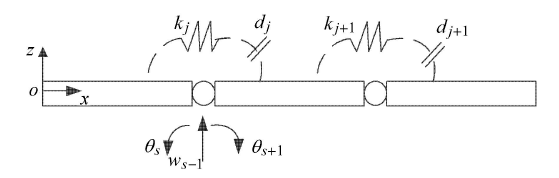
针对柔性航天器的可展结构在空间展开锁定后服役的动态特性,连接铰链采用平面回转铰链模型. 由于可展结构展开锁定后的变形模式以弯曲为主,因此本文主要考虑回转铰链侧向方向上的间隙.航天器的柔性体采用欧拉-伯努利梁进行建模. 每个梁单元节点采用两个自由度,即平面内的挠度和转角自由度.由于欧拉梁的变形形式以弯曲为主,因此将铰链简化为扭簧,如图1 所示,$o$-$xyz$ 为固定在中心刚体上的随体坐标系,第 $j$ 个铰链的刚度为 $k_j$,铰链间隙为 $d_j $;$w_{s - 1} $ 表示第 $j$ 个铰链对应的挠度自由度,$\theta _s$ 表示铰链左端连接梁节点的弯曲自由度,$\theta _{s + 1} $ 表示铰链右端连接梁节点的弯曲自由度.在铰接梁结构中 $\theta _{s + 1} \ne \theta _s $,这也是与连续梁结构的最大区别. $F_{a}$ 表示由铰链间隙产生的非线性接触碰撞力矢量,其中由第$j$个铰链间隙 $d_j $ 产生的非线性接触力 $F_{{a}j}$ 可表示为
图1
 新窗口打开|下载原图ZIP|生成PPT
图1含间隙铰接的柔性梁示意图
Fig. 1Schematic diagram of the flexible beam connected by joints with clearances
首先求得不含铰链的柔性梁的整体刚度、质量和阻尼矩阵,分别为 ${\pmb M}, {\pmb K}$ 和 ${\pmb C}$.
由铰链引入的质量矩阵 ${\pmb M}_j $ 为
其中,$h$ 为铰链所在位置的移动自由度,$m_j $ 为第 $j$ 个铰链的质量.
${\pmb K}_j $ 是由铰链引入的结构刚度阵,可表示为
其中,$k_j $ 为第 $j$ 个铰链的刚度,$h 1$ 和 $h 2$ 分别为此铰链所在位置的弯曲自由度编号.
则由铰链和柔性梁所组成的铰接组合结构的整体质量矩阵、刚度矩阵和阻尼矩阵分别为 $\bar {\pmb M}$,$\bar {\pmb K}$ 和 $\bar {\pmb C}$,可得到铰、梁组合结构的动力学方程为
其中,$ \bar {\pmb M} = {\pmb M }+ {\pmb M}_j $, $\bar {\pmb K} = {\pmb K} + {\pmb K}_j $, $\bar {\pmb C} ={\pmb C }+ {\pmb C}_j$, $\bar {\pmb F} = {\pmb F} + {\pmb F}_{a} $, ${\pmb x}$ 表示节点位移矢量,${\pmb F}$ 为外力矢量,${\pmb F}_{a} $ 表示由铰链间隙产生的非线性接触碰撞力矢量.
在铰、梁组合结构的动力学方程 (4) 中包含了铰链的质量和刚度,而在以往的铰接结构动力学建模中往往忽略了铰链的质量和刚度对系统整体动力学特性的影响. 然后对铰接结构采用模态截断,从而建立低维的动力学模型.
使用模态离散方法,则式 (4) 可以变换为
式中
其中,${\pmb \varPhi}$ 是模态矩阵,${\pmb q}$ 是模态坐标,$\hat{\pmb F}$ 是广义外力矢量,$\hat{\pmb F}_{h} $ 是由间隙引起的广义碰撞力矢量.
2 刚-柔耦合非线性动力学模型建立
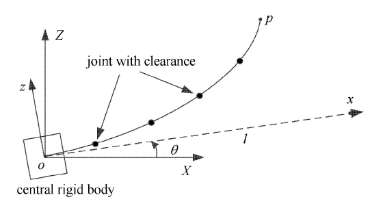
如图2 所示,$o$-$XYZ$ 为惯性坐标系,$o$-$xyz$ 为固定在中心刚体上的随体坐标系,按右手坐标系确定 $Y(y)$ 轴方向.本文研究单轴转动航天器,即中心刚体只考虑沿 $Y$ 轴方向的转动自由度,柔性梁只考虑 $xoz$ 平面内的振动.中心刚体的姿态角用 $\theta $ 表示. $2r_0 $ 表示中心刚体的边长,$l$ 表示柔性梁的长度. $x$,$y$ 和 $z$ 分别表示梁的长度、宽度和厚度方向,$w$ 表示 $z$ 方向的挠度.柔性梁上任意点 $P$ 在随体坐标系中的位置矢量 ${\pmb r}$ 为其中 ${\pmb i}$, ${\pmb j}$ 和 ${\pmb k}$ 分别是随体坐标系沿 $x$, $y$ 和 $z$ 轴的单位向量.
图2
 新窗口打开|下载原图ZIP|生成PPT
图2含间隙铰链的柔性航天器示意图
Fig. 2Schematic diagram of flexible spacecraft with clearance joints
点 $P$ 在惯性坐标系中的速度 ${\pmb v}$ 可表示为
则柔性航天器总的动能为
式中,$\dot {\theta }$ 表示航天器在惯性坐标系下的角速度矢量,$J_{1}$ 表示中心刚体的转动惯量,$\rho _1$ 表示梁的线密度.
柔性航天器的应变能可表示为
其中,$E$ 和 $I$ 分别表示柔性梁的弹性模量和截面惯性矩,$\theta _{j1} $ 和 $\theta _{j2} $ 分别表示连接第 $j$ 个铰链左右两端单元节点的转角,$n_j $ 表示铰链的数量.
根据哈密顿原理
可推导得到柔性航天器系统连续形式的刚柔耦合动力学方程
相对应的边界条件为
其中 $J$ 表示中心刚体和柔性体的转动惯量之和.
对铰、梁结构的弹性连续位移$w$进行离散化,可表示为 $w = {\pmb\varPhi}{\pmb q}$,其中 ${\pmb\varPhi}$ 为悬臂铰、梁结构的模态矩阵,${\pmb q}$ 为广义坐标. 结合 式 (5) 可得到离散形式的刚柔耦合非线性动力学方程
其中 ${\pmb H}$ 表示刚柔耦合矩阵,${\pmb H} = \int_\varOmega \left( {{\pmb r}^\times + {\pmb w}^\times } \right) N \text{d} m $,${\pmb w}$ 为参考点$P$的弹性位移在随体坐标系中的分量列阵,"$\times $'' 表示叉乘矩阵;$\hat{\pmb F}_{h} $ 表示由间隙引起的广义碰撞力矢量.
3 数值算法和控制算法
将由间隙产生的广义非线性铰链力 $\hat {\pmb F}_{h} $ 作为一个外力约束条件施加到非线性动力学模型中. 采用 Newmark 算法对非线性动力学方程 (15) 进行迭代求解.算法的输入为:$\bar {\pmb q}_0 $,$\dot {\bar{\pmb q}}_0 $,$\tilde{\pmb F}_0 $,$\gamma $,$\beta $,其中 $\bar{\pmb q}_0 = \left[\theta _{0} \ \ {\pmb q}_0 \right]^{T}$, $\dot {\bar{\pmb q}}_0 = \left[ {\dot {\theta }_{0} } \ \ {\dot{\pmb q}_{0} } \right]^{T}$ 和 $\tilde {\pmb F}\left( {0} \right) = \left[ \!\! \begin{array}{c} { - 2\dot {\theta }_0 {\pmb q}_0^{T} \hat {\pmb M}\dot{\pmb q}_0 } \\ {\hat{\pmb F}\left( {0} \right)}\end{array} \!\!\right]$ 分别为初始时刻方程 (15) 的广义位移、广义速度和广义外力,$\gamma $ 和 $\beta $ 分别为 Newmark 算法中的参数.
令
$ \tilde {\pmb M}\left( {0} \right) = \left[\!\! \begin{array}{cc} J + {\pmb q}_0^{T}\hat{\pmb M}{\pmb q}_0 & {\pmb H} \\ {\pmb H}^{T} & \hat{\pmb M} \end{array} \!\! \right] , \ \ \tilde{\pmb C}\left( {0} \right) = \left[\!\! \begin{array}{cc} {\bf 0} & {\bf 0} \\ {\bf 0} & \hat{\pmb C} \end{array} \!\! \right]\\ \tilde{\pmb K}\left( {0} \right) = \left[\!\! \begin{array}{cc} {\bf 0} & {\bf 0} \\ {\bf 0} & \hat{\pmb K} - \dot {\theta }_0^2 \hat{\pmb M} \end{array} \!\! \right] , \ \ \bar{\pmb q} = \left[\!\! \begin{array}{c} \theta \\ {\pmb q} \end{array} \!\! \right] $
其中 $\bar {\pmb q}$ 为耦合非线性动力学方程 (15) 的广义位移.
可求得初始时刻的广义加速度为
设定时间步长为 $\Delta t$,则总时间步长为 $n_s = t / \Delta t$, 对第 $i (i =0, 1, \cdots , n_s -1)$ 个时间步长进行循环:
(1) 求解第$i$个时间步长的广义位移 $\bar{\pmb q}\left( {i + {1}}\right)$、广义加速度 $\ddot {\bar{\pmb q}}\left( {i + {1}}\right)$ 和广义速度 $\dot {\bar{\pmb q}}\left( {i + {1}} \right)$;
(2) 根据公式 (1) 判断第 $( i +1)$ 个时间步长铰链碰撞是否发生;
(3) 利用 $\bar{\pmb q}\left( {i + {1}} \right)$ 和 $\dot {\bar{\pmb q}}\left( {i + {1}} \right)$ 计算第 $( i +1)$ 个时间步长的非线性质量矩阵 $\tilde{\pmb M}\left( {i + {1}} \right)$、非线性刚度矩阵 $\tilde{\pmb K}\left( {i + {1}}\right)$ 及广义力矩阵 $\tilde{\pmb F}\left( {i + {1}} \right)$:
到此循环结束. 从而求解出航天器的振动位移与姿态角、姿态角速度等信息.
将式 (15) 简化为线性形式并施加压电驱动力,可表示为
其中 $\hat{\pmb F}_{p} = {\pmb \varPhi}^{T}{\pmb K}_{u\varphi }{\pmb U}$ 表示施加在柔性梁上的广义压电驱动力矢量,${\pmb K}_{u\varphi }$ 是力电耦合矩阵,${\pmb U}$ 表示施加在压电驱动器上的电压,其中 ${\pmb U} =[ {U_1 } \ \ {U_2 } \ \ \cdots \ \ {U_r } ]^{T}$,其中 $U_\xi $ ($\xi = 1, 2, 3, \cdots , r)$ 为施加到各个压电驱动器上的电压,$\xi $ 是驱动器的数量. ${\pmb K}_{u\varphi } {\pmb U}$ 表示压电驱动器产生的等效驱动力,可根据压电驱动的载荷比拟方法求得[37].
则式 (21) 可以表示为
其中 ${\pmb M}_{s} = \left[\!\! \begin{array}{cc} J & {\pmb H }\\ {\pmb H}^{T} & \hat{\pmb M} \end{array} \!\! \right]$, $ {\pmb C}_{s} = \left[\!\! \begin{array}{cc} 0 & {\bf 0} \\ {\bf 0} & \hat{\pmb C} \end{array} \!\! \right]$, ${\pmb K}_{s} = \left[\!\! \begin{array}{cc} 0 & {\bf 0} \\ {\bf 0} & \hat{\pmb K} \end{array} \!\! \right]$.
由式 (22) 可得到系统状态空间方程
其中
$ {\pmb Z}=\left[\!\! \begin{array}{c} \bar{\pmb q} \\ \dot{\bar{\pmb q}} \end{array} \right] , \ \ \ {\pmb A}=\left [\!\! \begin{array}{cc} {\bf 0} & {\pmb I} \\ -{\pmb M}^{-1}_{s} {\pmb K}_{s} & -{\pmb M}^{-1}_{s} {\pmb C}_{s} \end{array} \right] $
$ {\pmb B}=\left[\!\! \begin{array}{c} {\bf 0} \\ {\pmb M}^{-1}_{s} [ 0 \ \ {\pmb \varPhi}^{T} {\pmb K}_{u\varphi} ]^{T} \end{array} \right] $
根据线性二次型最优控制算法 (LQR),求得控制增益矩阵 ${\pmb K}_{f} $,使性能指标
$ J = \dfrac{1}{2}\int_0^\infty \left( {{\pmb Z}^{T}{\pmb Q}{\pmb Z} + {\pmb U}^{T}{\pmb R}{\pmb U}} \right)\text{d} t $
取极小值,其中 ${\pmb Q}$ 和 ${\pmb R}$ 分别是控制参数矩阵. 则控制输入 电压 ${\pmb U }= - {\pmb K}_{f} {\pmb Z}$.
4 数值模拟与讨论
4.1 模型验证
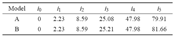
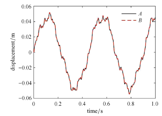
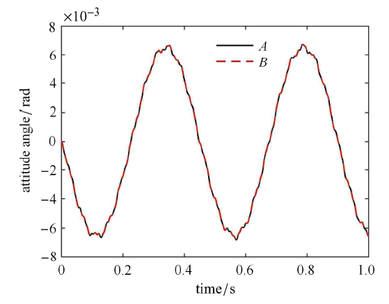
从刚柔耦合系统的固有频率和动力学响应两个角度对所建的模型进行验证. 柔性梁在中点处含有一个连接铰链. 令铰链的间隙尺寸为 0 且铰链连接刚度取无限大,此时铰、梁模型应该趋近于连续梁的模型. 柔性梁的弹性模量 $E=70$ GPa,泊松比 $\nu=0.3$,密度 $\rho =2700$ kg/m$^{3}$,梁长 $l =3$ m,宽 $b =0.2$ m,厚度 $\bar {h} =0.015$ m,后文中的梁均采用此材料参数和几何参数. 中心刚体边长 $2 r_{0}=0.4$ m,转动惯量 $J_{1} =100$ kg$ \cdot$m$^{2}$. 计算带间隙铰接航天器的固有频率、梁自由端处的振动位移以及航天器的姿态角,并与具有连续梁无铰链的刚柔耦合航天器进行对比,结果如表1、图3 和图4 所示,其中模型A表示本文含铰链的模型,模型B表示具有连续梁无铰链的航天器模型,$i_{1}$,$i_{2}$,$i_{3}$,$i_{4}$,$i_{5}$ 分别表示航天器的前 5 阶固有频率,$i_{0}$ 表示第 0 阶固有频率,单位均为 Hz.表1 中第 0 阶的频率为 0 Hz,其对应于航天器的姿态运动 (刚体转动),此时柔性梁不发生弹性变形.从表1、图3 和图4 中可以看出,二者均吻合良好,这也初步验证了本文所建模型的正确性,可用于后续的含间隙刚柔耦合系统的动力学特性分析.Table 1
表1
表1固有频率对比
Table 1
 |
新窗口打开|下载CSV
图3
 新窗口打开|下载原图ZIP|生成PPT
图3两模型的振动位移的比较
Fig. 3Comparison of vibration displacement of the two models
图4
 新窗口打开|下载原图ZIP|生成PPT
图4两模型的航天器姿态角的比较
Fig. 4Comparison of attitude angle of spacecraft of the two models
4.2 铰链参数及中心刚体转动惯量对航天器动力学特性的影响
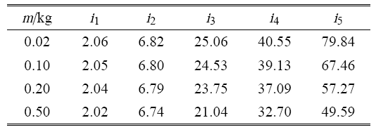
柔性梁在中点处由一个铰链连接,令铰链的连接刚度为 $k_{g} = k_{l} $,其中 $k_{l} = 100 EI / l^2$. 不断增大铰链的质量 $m$,求解航天器的前 5 阶固有频率,单位为 Hz,如表2 所示,分析铰链的质量对航天器固有频率的影响. 从表2 中可看出,铰链的质量越大,航天器的固有频率越低. 因此在进行铰链设计时,应该尽量减小铰链的质量,以增大航天器系统整体的固有频率.Table 2
表2
表2不同铰链质量时航天器的固有频率
Table 2
 |
新窗口打开|下载CSV
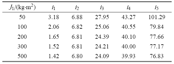
令铰链刚度 $ k_{g} = k_{l}$,铰链质量 $m =0.02$ kg,当航天器的中心刚体转动惯量 $J_{1}$ 取不同值时,求解航天器的前五阶固有频率,单位为 Hz,如表3 所示,以分析中心刚体转动惯量对航天器固有频率的影响.
Table 3
表3
表3不同中心刚体转动惯量时航天器的固有频率
Table 3
 |
新窗口打开|下载CSV
从表3 中可以看出,中心刚体的转动惯量越大,航天器的固有频率越低,特别地,中心刚体转动惯量对柔性航天器基频的影响相比其他阶频率更显著.
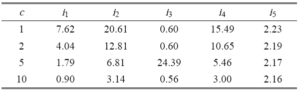
令铰链质量 $m =0.02$ kg,中心刚体转动惯量 $J_1 =100$ kg$\cdot$m$^2$,铰链连接刚度 $k_{g} =ck_{l}$,当铰链刚度系数 $c$ 取不同值时,分析航天器的前五阶固有频率的变化情况.求解出不同铰链刚度时航天器的每阶固有频率相对无铰链航天器的固有频率的百分比,单位为 %,如表4 所示.从表4 中可以看出,铰链的连接刚度越大,则航天器的固有频率越高. 连接刚度对偶数阶固有频率 (第二、四阶固有频率) 的影响要比对奇数阶固有频率 (第一、三阶、五阶固有频率) 的影响大.
Table 4
表4
表4不同铰链刚度时航天器固有频率的百分比
Table 4
 |
新窗口打开|下载CSV
由上可知航天器的固有频率与铰链的连接刚度、质量及中心刚体的转动惯量均相关,这些参数均会影响柔性航天器的固有特性. 因此在进行柔性航天器的动态性能设计时,应该着重考虑这些参数的选取.
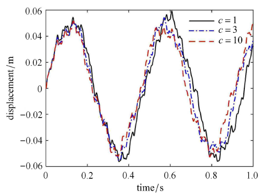
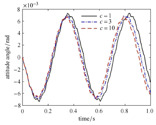
令铰链间隙尺寸为 $d =0.005$ rad,铰链的质量 0.02 kg,中心刚体转动惯量为 100 kg $\cdot$m$^2$,分析铰链连接刚度对航天器动力学响应的影响. 铰链连接刚度为 $k_{g} = ck_{l}$,当参数 $c$ 分别取 1,3 和 10 时,航天器的柔性体自由端处的振动位移和姿态角响应分别如图5 和图6 所示.从图中可以看出,随着铰链刚度的增大,柔性体振动位移和航天器姿态角不断减小.这是因为铰链刚度越大,则刚柔耦合航天器系统的整体刚度就越大,那么系统在外界干扰下的振动响应和姿态响应就越小.
图5
 新窗口打开|下载原图ZIP|生成PPT
图5不同铰链连接刚度时柔性体的振动位移
Fig. 5Vibration displacements of the flexible body with different joint connection stiffness
图6
 新窗口打开|下载原图ZIP|生成PPT
图6不同铰链连接刚度时航天器的姿态角
Fig. 6Attitude angle of the spacecraft with different joint connection stiffness
4.3 铰链间隙尺寸对柔性航天器动力学响应的影响
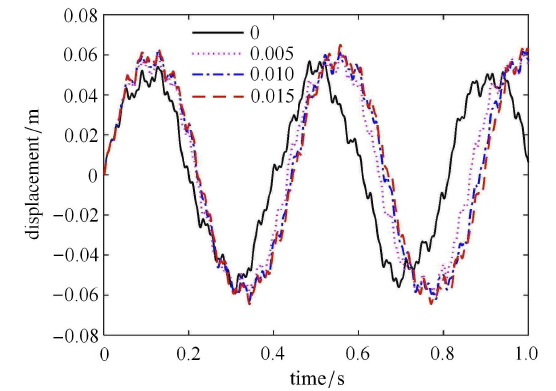
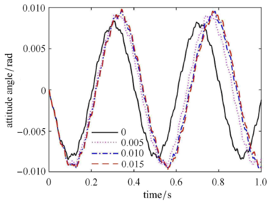
当铰链的间隙具有不同的尺寸时,航天器刚柔耦合系统的动态特性会随之发生变化. 下面分析间隙尺寸的大小对航天器动力学特性的影响. 柔性梁在中点处由一个铰链连接,铰链的质量为0.02 kg,中心刚体转动惯量为 80 kg$\cdot $m$^2$,铰链连接刚度 $k_{g} =0.8 k_{\rm l}$,本文暂不考虑航天器柔性体的阻尼.当铰链具有不同间隙尺寸时柔性体的振动位移响应和航天器的姿态角响应分别如图7 和图8 所示.图7 和图8 分别为当间隙尺寸为 0 rad,0.005 rad,0.010 rad 和 0.015 rad 时柔性体在自由端处的振动位移以及航天器的姿态角. 从图7 和图8 中可以看出,随着间隙尺寸的增大,柔性体的振动位移响应及航天器的姿态角响应不断增大,这是因为 随着铰链间隙的增大,航天器变得更柔,从而刚度变小,刚柔耦合系统的频率变低,所以导致在外界干扰下柔性体的振动 位移幅值和航天器的姿态角幅值变大.从图7 和图8 中还可以看出,随着间隙尺寸增大,响应曲线幅值的峰值在时间轴上向右移,这说明系统的第一阶频率不断减小. 图9 为间隙尺寸为 0.010 rad 时铰链碰撞力矩的幅值,从图中可以看出,当输出的铰链碰撞力矩为 0 时,此刻铰链未发生碰撞.这些仿真结果符合实际的物理规律,反映了铰链间隙对航天器结构振动和姿态运动的影响.图7
 新窗口打开|下载原图ZIP|生成PPT
图7不同间隙大小时柔性体的振动位移
Fig. 7Vibration displacements of the flexible body with different clearance sizes
图8
 新窗口打开|下载原图ZIP|生成PPT
图8不同间隙大小时航天器的姿态角
Fig. 8Attitude angle of the spacecraft with different clearance sizes
图9
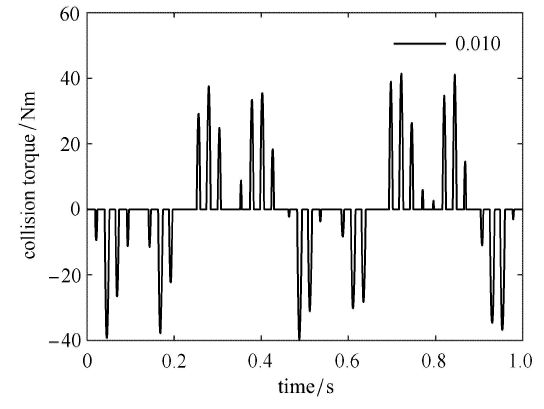 新窗口打开|下载原图ZIP|生成PPT
图9当间隙为 0.01 rad 时铰链的碰撞力矩
Fig. 9Collision torque of the joint with clearance 0.01 rad
4.4 铰链数目对柔性航天器动力学特性的影响
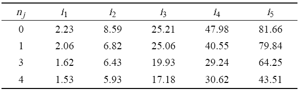
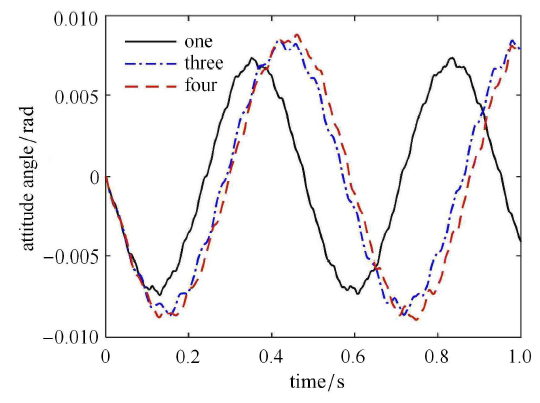
令铰链的质量为 0.02 kg,中心刚体转动惯量为 100 kg$\cdot$m$^{2}$,铰链连接刚度为 $k_{g} = k_{\rm l}$,柔 性梁的长度为 3 m. 当铰链数目 $n_j $ 分别为 1,3 及 4 个,铰链的位置布局如图10 所示,分析在不同铰链数目下航天器的前五阶固有频率,单位为 Hz,如表5 所示,其中铰链数目为 0 即表示具有连续梁的无铰链航天器. 从表5 中可以看出,铰链数目增多,航天器的固有频率就随之降低.铰链数目的增多降低了刚柔耦合系统的整体刚度.当航天器中只含有一个铰链时,前五阶固有频率相比具有连续梁的航天器均有减小,这与只含有一个铰链的悬臂梁的固有频率特性有较大的差异.只含有一个铰链的悬臂梁,相比连续的悬臂梁,结构的偶数阶固有频率有一定程度的降低,而奇数阶的固有频率几乎保持不变.这主要是由刚柔耦合航天器的振型与铰链位置的关系造成的.这也反映了航天器的中心刚体的刚体运动对柔性体的固有特性产生的影响. 令各铰链的间隙尺寸均为 $d=0.005$ rad,分析含间隙铰链的数目对航天器动力学响应的影响,分别如图11 和图12 所示,图11 为不同铰链数目时航天器柔性体在自由端处的振动位移,图12 为不同铰链数目时航天器的姿态角.从图中可以看出铰链数目越多,柔性体的振动位移和航天器的姿态角就越大.随着铰链数目增多,振动位移和姿态角曲线幅值的峰值在时间轴上均向右移,这也验证了刚柔耦合航天器的基频随着铰链数目的增多而不断降低.图10
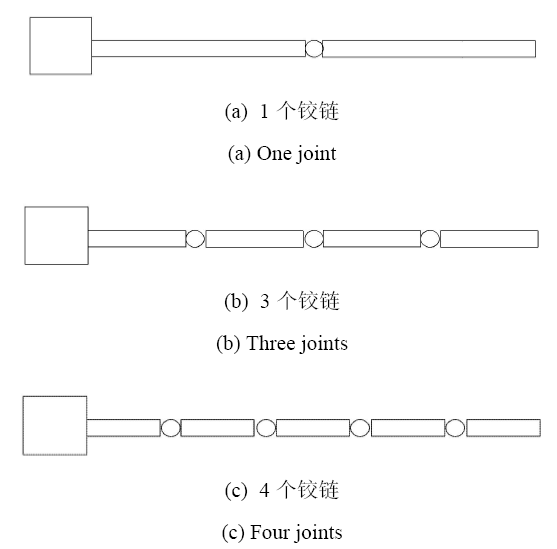 新窗口打开|下载原图ZIP|生成PPT
图10不同铰链数目的航天器示意图
Fig. 10Diagram of spacecraft with different number of joints
Table 5
表5
表5不同铰链数目时航天器的固有频率
Table 5
 |
新窗口打开|下载CSV
图11
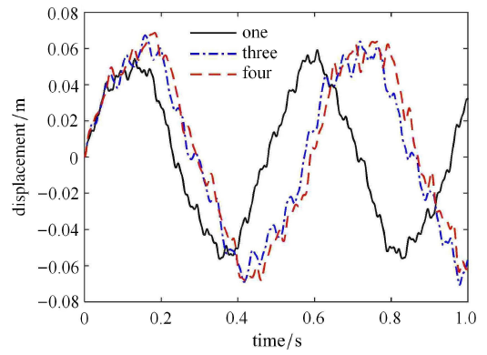 新窗口打开|下载原图ZIP|生成PPT
图11不同铰链数目时柔性体的振动位移
Fig. 11Vibration displacements of the flexible body with different number of joints
图12
 新窗口打开|下载原图ZIP|生成PPT
图12不同铰链数目时航天器的姿态角
Fig. 12Attitude angle of the spacecraft with different number of joints
4.5 基于压电纤维复合材料 (MFC) 驱动器的主动控制
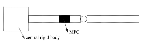
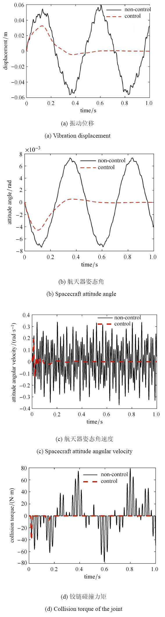
柔性航天器的参数如 4.4 节中所示,铰链数目 $n_j =1$,铰链间隙尺寸为 0.005 rad. 一对 MFC 驱动器沿柔性梁上下对称粘贴铺设,如图13 所示,其中 MFC 左端距离梁根部的长度为 0.9 m,其压电纤维沿柔性梁轴向方向铺设.MFC 驱动器的长度为 0.3 m,宽度为 0.2 m,厚度为 0.0003 m,其材料参数为:压电应变常数 ($\times $10$^{ -12}$ C/N):$d_{11} =400$,$d_{12} =-170$;弹性常数:$E_{1} =30.34$ GPa,$E_{2} =15.86$ GPa,$\mu _{12}=0.31$,$\mu _{21} =0.16$,$\mu _{23} =0.31$,$G_{12} =5.52$ GPa.采用 LQR 最优控制对柔性航天器进行主动振动抑制,控制器的控制参数分别为 $Q = {dig} (600)_{12\times 12}$,$R =0.1$.在梁的自由端点处施加一个脉冲载荷:激励幅值为 300 N,激励时间为 0.005 s,位移响应输出点为梁的自由端点.计算未施加控制前和施加控制后航天器的振动位移、姿态角、姿态角速度以及铰链的碰撞力,如图14 所示.图13
 新窗口打开|下载原图ZIP|生成PPT
图13粘贴 MFC 驱动器的带间隙铰链航天器示意图
Fig. 13Schematic of spacecraft with clearance joints with MFC actuator
图14
 新窗口打开|下载原图ZIP|生成PPT
图14无控和有控下航天器系统动态特性的比较
Fig. 14Comparison of dynamic characteristics of the spacecraft system between non-control and control models
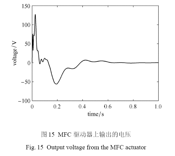
从图14 中可以看出,利用 LQR 最优控制,通过 MFC 驱动器对柔性梁施加主动控制力矩,在外界载荷激励下,柔性梁的振动位移和航天器的姿态角均得到了快速衰减,航天器的姿态角速度也快速稳定到 0,这说明采用 MFC 主动控制能够抑制航天器的姿态振荡和柔性附件振动,并且可以保持较好的姿态稳定度.通过施加主动振动抑制,在 0.2 s 之后铰链间的碰撞力就逐渐趋向于 0,这说明施加主动控制缓解了铰链部件间的相互碰撞,有效减缓了铰链间隙对航天器姿态运动与结构振动造成的影响作用.图15 为施加在MFC驱动器上的电压,施加的最大电压将近 130 V,远未超过 MFC 的最大输出电压 1500 V.
图15
 新窗口打开|下载原图ZIP|生成PPT
图15MFC 驱动器上输出的电压
Fig. 15Output voltage from the MFC actuator
因此采用 MFC 驱动器,能够实现含铰链间隙的柔性航天器姿态运动与结构振动的协同控制,并且可以有效抑制铰链间隙给柔性航天器动力学特性带来的影响.
5 结论
针对大型柔性航天器展开锁定后运动副间隙对系统动态特性造成的影响问题,本文开展了含间隙铰接的柔性航天器刚柔耦合动力学建模和控制研究. 利用哈密顿原理和模态离散方法,构建了含间隙铰链的航天器刚柔耦合非线性动力学模型,采用 Newmark 算法求解并分析了含间隙铰接柔性航天器的动力学特性,着重研究了铰链间隙对航天器姿态运动和结构振动的影响作用,最后利用 MFC 驱动器对航天器施加主动控制. 研究结果表明,铰链的连接刚度越低,中心刚体的转动惯量越大,则刚柔耦合航天器系统的固有频率越低,航天器的姿态角响应和振动位移响应就越大;随着航天器中铰链间隙尺寸的增大及含间隙铰链数目的增多,刚柔耦合航天器的整体刚度逐渐减小,系统固有频率不断降低,而在外界激励下柔性航天器的姿态角幅值和振动位移幅值不断增大;通过基于 MFC 驱动器的主动控制,能够实现含铰链间隙的柔性航天器姿态运动与结构振动的协同控制,并有效减缓铰链间隙对航天器动态特性造成的影响.参考文献 原文顺序
文献年度倒序
文中引用次数倒序
被引期刊影响因子
[本文引用: 1]
[本文引用: 1]
[本文引用: 1]
[本文引用: 1]
[本文引用: 1]
[本文引用: 1]
[本文引用: 1]
[本文引用: 1]
[本文引用: 1]
[本文引用: 1]
[本文引用: 1]
[本文引用: 1]
DOIURL [本文引用: 2]

基于近年来计及间隙影响的运动副建模以及含间隙机械系统动力学的研究, 综述间隙运动副连续接触模型、经典碰撞模型、连续接触力模型以及旋转副三维间隙模型等的研究进展, 介绍间隙模型在机械系统动力学非线性特性分析、性能评价与可靠性评估等方面的应用情况, 详细探讨考虑黏滞–滑动过程和接触表面形貌的间隙建模、共形接触建模、不确定参数的含间隙系统动力学分析、运动精度评估以及运动副间隙设计等未来应重点研究的若干关键技术问题。
DOIURL [本文引用: 2]
Recent developments in modeling of clearance joints and dynamics of mechanical systems with clearances are reviewed. Different modeling approaches for clearance joints are summarized firstly, which comprise the massless link approach, the non-smooth dynamics approach, the contact force approach and the 3D revolute joint approach. Then, applications of these approaches in the study of the nonlinear dynamics, and performance and reliability evaluation of the mechanical systems with clearances are systematically reviewed. Finally, the key problems and priorities which need to be further studied are proposed, including the modeling of clearace joints considering stick-slip phenomenon, contact surface profile and conformal contact condition, the dynamic analysis and kinematic accuracy evaluation of mechanical systems with both clearances and uncertainties, and the design for clearance joints.
[本文引用: 1]
DOIURL [本文引用: 1]
DOIURL
[本文引用: 1]
DOIURL
[本文引用: 1]
[本文引用: 2]
[本文引用: 2]
DOIURL
DOIURL
[本文引用: 1]
[本文引用: 1]
[本文引用: 1]
DOIURL [本文引用: 1]
DOIURL [本文引用: 2]
[本文引用: 2]
[本文引用: 2]
DOIURL
DOIURL [本文引用: 1]
[本文引用: 1]
[本文引用: 1]
