 ,?,2), 陈晓宇*, 张云清,*,3)
ROLL CHARACTERISTICS OF ALL-TERRAIN VEHICLE BASED ON CROSSING DOUBLE AIR CHAMBER PNEUMATICALLY INTERCONNECTED SUSPENSION$^{\bf 1)}$
Wang Zhen*, Zhu Hengjia,?,2), Chen Xiaoyu*, Zhang Yunqing,*,3)通讯作者: 2)祝恒佳,讲师,主要研究方向:机械系统动力学,民航智能装备. E-mail:hjzhu@cauc.edu.cn;3)张云清,教授,主要研究方向:多体系统动力学,车辆动力学与控制. E-mail:zhangyq@hust.edu.cn
收稿日期:2020-03-15接受日期:2020-04-15网络出版日期:2020-07-18
| 基金资助: |
Received:2020-03-15Accepted:2020-04-15Online:2020-07-18
作者简介 About authors

摘要
设计了一种采用囊式空气弹簧的交叉型双气室空气互联悬架 (PIS 悬架),并应用于侧翻事故发生率极高的全地形车上. 建立了交叉型双气室气体耦合 AMEsim 模型与全地形车整车动力学 ADAMS/Car 模型,通过将前者模型中的空气弹簧弹性力作为整车动力学模型的输入变量,将后者模型中的空气弹簧压缩伸张位移作为气体耦合模型的输入变量,建立了完整的机械-气体耦合多自由度动力学联合仿真模型. 通过 J 型弯高速典型仿真实验对搭载 PIS 悬架、双气室非互联悬架 (UN-PIS 悬架) 和普通螺旋弹簧悬架 (HS 悬架) 的全地形车进行侧倾特性对比研究. 研究结果显示,PIS 悬架若关闭互联管路,则会形成 UN-PIS 非互联状态,使悬架刚度瞬间大幅上升,平顺性瞬间变差,而具有相同垂向刚度的 PIS 悬架与 HS 悬架,前者能够提供更多的侧倾角刚度. 研究了气路系统 中影响动态侧倾特性的相关因子,包括连接管路管长、管径、附加气室容积. 研究表明,互联管路管长越小,越有利于提升全地形车侧倾特性,存在临界管径,管径小于或大于该值时,均会小幅度提升侧倾特性,附加气室容积越小,侧倾角刚度越大,为 PIS 悬架气路系统设计提供理论依据.
关键词:
Abstract
For the all-terrain vehicle with extremely high incidence of rollover accidents, a cross-type double air chamber pneumatically interconnection suspension using a capsule air spring is designed. A crossing double air chamber gas coupling AMEsim model and an all-terrain vehicle dynamics ADAMS/Car model are established. By taking the change of elastic force of air spring in the former model as the input variable of the vehicle dynamics model, and the compressional displacement of air spring in the latter model as the input variable of the gas coupling model, a complete mechanical-pneumatically coupling multi-degree of freedom dynamic joint simulation model is established. The roll characteristics of an all-terrain vehicle equipped with a crossing double air chamber pneumatically interconnected suspension(PIS), a crossing double air chamber pneumatically unconnected suspension(UN-PIS), and a common helical spring suspension(HS) are compared with the simulation experimental conditions. The results show that if the PIS system closes the interconnection pipeline, the UN-PIS system will be formed, which causes the suspension stiffness to rise sharply in an instant and the ride performance to deteriorate in an instant. On the premise of guarantee consistent vertical stiffness, PIS can provide greater lateral stiffness than HS. The factors affecting the dynamic roll characteristics in the gas pipeline system are researched, including the pipe length, pipe diameter and the volume of additional air chamber. The research shows that the shorter the pipe length is, the more beneficial it is to improve the roll characteristics of all-terrain vehicles. And there is a critical pipe diameter, when the pipe diameter is less than or greater than this value, the roll characteristics will be slightly improved. And the smaller the volume of the additional air chamber, the greater the lateral stiffness. Which provides a theoretical basis for the design of PIS system.
Keywords:
PDF (15208KB)元数据多维度评价相关文章导出EndNote|Ris|Bibtex收藏本文
本文引用格式
王震, 祝恒佳, 陈晓宇, 张云清. 基于交叉型双气室空气互联悬架的全地形车侧倾特性研究$^{\bf 1)}$. 力学学报[J], 2020, 52(4): 996-1006 DOI:10.6052/0459-1879-20-071
Wang Zhen, Zhu Hengjia, Chen Xiaoyu, Zhang Yunqing.
引言
全地形车,是一种可用于非铺装路面驾驶且具有极强的通过性的一类汽车,其前悬架多为双横臂独立悬架,后悬架为双横臂或多连杆独立悬架等[1-3]. Kurczyk 等[4]基于全地形车设计了一款模糊控制的半主动悬架,Koch 等[5]基于全地形车设计了一款自适应型主动悬架. Ben 等[6]基于全地形车半车模型,分别对被动、半主动和主动悬架进行了平顺性与操稳特性的分析. 考虑到能耗与可靠性问题,半主动、主动悬架对于多恶劣工况运行的全地形车并无优势. 而互联悬架不仅能耗低,而且可以在不同车轮间传递力的作用[7],通过调节相关悬架参数使全地形车获得优异的动力学性能. 根据连接介质的不同,互联悬架可分为机械互联悬架、油气互联悬架[8-9]、液压互联悬架[10-11]和空气互联悬架.空气互联悬架的概念和结构最早由 William[12]于 1959 年提出并申请专利,其非线性刚度特性以及优异的减振性能吸 引了国内外****研究. Bhave[13]建立了具有垂向、俯仰两自由度运动的空气互联悬架动力学模型,然而推导过程没有考虑空气流动过程的损失,与实际工况误差较大. Kat 等[14]建立了基于三轴半挂车的纵向互联空气悬架的数学模型,并通过实验进行了验证. Li 等[15]通过仿真和台架试验的方式研究了单气室纵向和横向互联形式对车辆消扭、抗侧倾、抗俯仰等性能的影响. 李仲兴 等[16]针对横向空气互联悬架的侧倾角刚度进行了影响因素的定性分析,提出了一种互联管径选定方法. Zhu 等[17-18]研究了空气弹簧部件的力学模型并提出一种新的空气弹簧-管路-附加气室系统的动力学模型,解释了空气 弹簧幅频特性与气囊橡胶材料,摩擦之间的关系. 但以上空气互联悬架的互联型式局限于同轴两侧的单气室通过单一气动管路联通的互联形式,该互联型式可以有效降低全地形车在不平坦路面上车身振动情况,但由于其侧倾刚度低,高速转弯时车身侧倾严重,导致汽车侧倾特性较差.
动力学仿真与控制技术在解决航天器[19-21]、多足机器人[22-24]等科学问题方面做出了巨大贡献. 而针 对主动控制互联悬架的动力学仿真研究方面,文献[25,26,27] 进行了相关探索,研究表明,采用适当的控制逻辑对液压互联悬架的伺服阀进行控制从而改变悬架互联状态可以有效改善行驶平顺性与操纵稳定性.
Zhu 等[28]和 Zhang 等[29]分别研究了交叉型双气室空气互联悬架、交叉型液压互联悬架车辆的自由振动模态,通过侧倾模态与垂直模态的对比进行侧倾刚度与垂向刚度的定性分析. Smith 等[30]对交叉型液压互联悬架的操稳特性进行了理论分析. 周敏等[31]将交叉型液压互联悬架应用于全地形车,并证明液压互联悬架系统可提升车辆侧倾特性. 由此推测,交叉型双气室空气互联悬架也具有提升车辆侧倾特性的性质.
本文设计了一种交叉型双气室空气互联悬架并应用于侧翻事故发生率极高的全地形车上,首先从悬架垂向刚度与侧倾角刚度分析 的角度确定PIS 和 UN-PIS,HS 二者之间关系,然后将 AMEsim气体耦合模型与 ADAMS/Car 全地形车动力学模型交互,并经过J型弯高速典型仿真工况分析,对交叉型空气互联悬架的侧倾特性进行研究,最后通过影响因子敏感度分析,为 PIS 系统气路参数选取提供理论依据.
1 侧倾平面交叉型双气室气体耦合模型
本节首先进行侧倾平面交叉型双气室空气互联悬架结构分析,然后进行了悬架的刚度分析. 基于 AMEsim 平台建立了双气室气体耦合模型,该模型包含了空气动力学、流体力学与热力学基本理论,为简化仿真流程,提高仿真效率,在建模时进行以下假设:(1) 空气弹簧系统内气体为理想气体,满足理想气体状态方程.
(2) 气囊线性化假设:各气囊有效面积为定值,气囊的体积变化全部由自身垂向压缩伸长导致.
(3) 气体流通为等熵过程.
(4) 忽略空气弹簧橡胶材料的影响.
1.1 模型分析
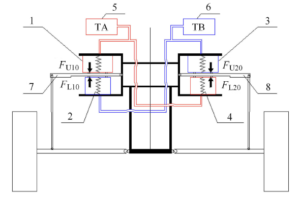
如图 1 所示,交叉型双气室空气互联悬架包括左右两侧空气悬架系统,左侧空气悬架系统由左上气室,左下气室和左摇臂组成,右侧空气悬架系统由右上气室,右下气室与右摇臂组成. 左上气室通过管路与右下气室、附加气室 TA 联通,右上气室通过管路与左下气室、附加气室 TB 联通. 左摇臂连接左侧推杆与左侧上下两气室,右摇臂连接右侧推杆与右侧上下两气室.悬架跳动时,推杆带动摇臂绕支点转动,进而带动上下气室压缩与拉伸,实现气体在交叉气室中流通.图1
 新窗口打开|下载原图ZIP|生成PPT
图1交叉型双气室空气互联悬架示意图
1-左上气室,2-左下气室,3-右上气室,4-右下气室, 5-附加气室 TA,6-附加气室 TB,7-左摇臂,8-右摇臂
Fig.1Schematic diagram of PIS
1-Left upper chamber, 2-Left lower chamber, 3-Right upper chamber, 4-Right lower chamber, 5-Additional chamber TA, 6-Additional chamber TB, 7-Left rocker arm, 8-Right rocker arm
当搭载此互联悬架的全地形车向右转弯时,车身朝左侧侧倾,此时,左侧上气室被压缩,下气室被拉伸,气体的流通使右侧上气室收缩,下气室膨胀,使右摇臂绕车身连接轴处逆时针转动,从而产生"右侧车身被摇臂往下拉"的效果,提升了过弯时全地形车的抗侧倾性能.
1.2 悬架刚度分析
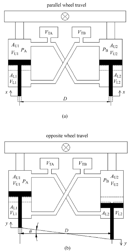
交叉型双气室空气互联刚度分析模型 如图 2 所示,图 2(a) 为模拟平行轮跳试验模型,图 2(b) 为模拟异步轮跳试验模型. 静平衡状态下,两条管路内压强 $P_{\rm A}$ 和 $P_{\rm B}$ 的初始值为 $P_0 $,左右上气室体积 $V_{\rm U1} $ 和 $V_{\rm U2} $ 始值为 $V_{\rm U0} $,左右下气室体积 $V_{\rm L1}$ 和 $V_{\rm L2} $ 初始值为 $V_{\rm L0}$,两附加气室 $V_{\rm TA} $ 和 $V_{\rm TB} $ 初始值为 $V_{\rm T0}$. 假设上下气室有效面积在气室压缩和拉伸过程中为定值 $A_{\rm U0}$ 和 $A_{\rm L0}$,为定性分析悬架刚度并简化分析过程,将悬架杠杆比设为 1.图2
 新窗口打开|下载原图ZIP|生成PPT
图2交叉型双气室空气互联刚度分析模型
Fig.2Stiffness analysis model of PIS
1.2.1 PIS 系统刚度分析
(1) PIS 系统垂向刚度分析
如图 2(a),对交叉型双气室空气互联悬架进行同向轮跳实验,固定两侧簧上质量,左右两侧活塞同时施加向上的微小位移 $x$. 左右两侧空气弹簧提供的合力有
根据理想气体状态方程有
其中,$\gamma $ 为多变指数. 外部激振频率较低时 $\gamma = 1$,此时空气弹簧表示静刚度,当外部激振频率较高时 $\gamma = 1.4$,此时空气弹簧表示动刚度. 本试验过程中取$\gamma = 1$.
对式 (2) 和式 (3) 左右两边关于 $x$ 求导,可得
由于活塞相对位移较小,忽略各气室气压、体积相对初始值变化量,并定义若气室体积减小则其关于位移求导为负,反之为正. 对式 (1) 左右两边关于位移$x$求导,并将式 (4) 和式 (5) 代入,可得 PIS 互联悬架垂向刚度
(2) PIS 系统侧倾角刚度分析
如图 2(b),对交叉型双气室空气互联悬架进行异步轮跳实验,固定两侧簧上质量,左右两侧活塞分别同时施加向上、向下的微小位移 $y$,地面绕汽车中心线与地面交点处转动了一个与汽车侧倾角相等的角度 $\theta $,悬架对地面施加一个阻止其转动的力矩 $T$
将式 (2) 和式 (3) 左右两边关于 $y$ 求导,可得
并且由几何关系
由于活塞相对位移较小,忽略各气室气压、体积相对初始值变化量,并定义若气室体积减小则其关于位移求导为负,反之为正. 对式 (7) 左右两边关于$\theta $求导,并将式 (8) $\sim$ 式 (10) 代入可得 PIS 互联悬架侧倾角刚度
1.2.2 UN-PIS 系统刚度分析
(1) UN-PIS 系统垂向刚度分析
UN-PIS 系统垂向刚度分析过程与 PIS 系统一致,但由于 UN-PIS 系统管路断开,使得左右两侧悬架相互独立,不存在相互影响. 双气室空气弹簧垂向刚度即为 UN-PIS 系统垂向刚度
(2) UN-PIS 系统侧倾角刚度分析
由侧倾角刚度公式,可得
1.2.3 刚度对比
(1) PIS 与 UN-PIS 系统垂向刚度、侧倾角刚度对比. 搭载交叉型双气室空气互联悬架的同一台全地形车,管路联通为 PIS 互联悬架,管路断开则为 UN-PIS 非互联悬架. 管路断开前后瞬间的垂向刚度分别为式 (6) 和式 (12),侧倾角刚度分别为式 (11) 和式 (13),分别进行比较
由上式可知,PIS 互联悬架的垂向刚度与侧倾角刚度远小于 UN-PIS 非互联悬架. 即搭载交叉型双气室空气互联悬架的全地形车,管路断开瞬间形成 UN-PIS 系统,造成垂向刚度与侧倾角刚度瞬间增强,整车平顺性瞬间恶化.
(2) 等垂向刚度 PIS 与 HS 系统的侧倾角刚度对比. 假定普通螺旋弹簧 HS 刚度与 PIS 互联悬架垂向刚度相同,即定义 $K_{\rm HS} = K_{\rm PIS} $,则有
由侧倾角刚度公式,HS系统侧倾角刚度为
根据式 (11) 和式 (17),有
上式表明,具有相同垂向刚度的交叉型双气室空气互联悬架 PIS 和传统螺旋弹簧悬架 HS,前者较后者可以提供更多的侧倾角刚度,表明 PIS 系统较普通螺旋弹簧悬架 HS 可以在保证平顺性的前提下有效抑制转弯工况下车身的侧倾.
1.3 单气室 AMEsim 模型
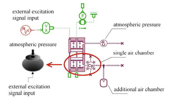
如图 3 所示为 AMEsim 中创建的单气室空气弹簧模型. 下活塞单元模拟单气室气囊垂向压缩拉伸过程,将下活塞单元与可变容积气室连接,以模拟单气室组件 (如图 3 圈内所示);上活塞单元与定容积气室连接,且上活塞单元与下活塞单元对顶连接,以模拟气囊上表面所受大气压力;外部激励信号与上活塞连接,该激励信号将同时作用于上下两活塞,以模拟摇臂与气室连接点处位移激励对气室的作用.图3
 新窗口打开|下载原图ZIP|生成PPT
图3单气室空气弹簧 AMEsim 模型
Fig.3Single chamber AMEsim model
特别的,所述上活塞单元与下活塞单元直径相同,均为气囊有效直径,所述定容积气室的压强设定为 $1.0 \times 10^5$Pa,且容积设置为无限大,以排除上活塞单元运动对定容积气室压强的影响. 该单气室空气弹簧支撑力为
气室模型内部压强 $P_{\rm i}$ 为绝对压强,且 $P_{\rm i}$ 的安全工作区间处于在 $(1.5\sim7.0)\times 10^5$Pa 之间,若忽略大气压 $P_{\rm a}$ 对该空气弹簧支撑力的影响,可使计算误差最高可达 67%,故建模过程中大气压不可忽略.
1.4 侧倾平面空气互联悬架 AMEsim 模型
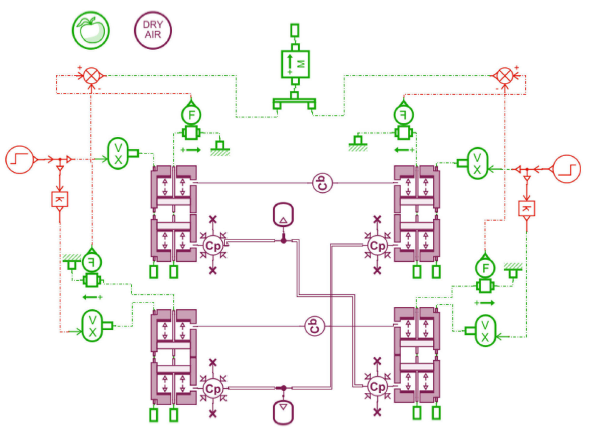
根据气体流通路径,结合前文创建的单气室 AMEsim 模型,在 AMEsim 中进行半车侧倾平面空气互联悬架模型搭建,如图 4 所示.图4
 新窗口打开|下载原图ZIP|生成PPT
图4半车侧倾平面空气互联悬架 AMEsim 模型
Fig.4Half car roll plane of PIS AMEsim model
值得注意的有,左上气室与左下气室所接受位移激励信号符号相反,以模拟实际摇臂转动对上下气室的压缩拉伸作用,上气室弹簧力减下气室弹簧力等于单侧空气弹簧支承力.
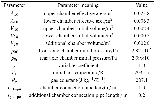
结合全地形车前后轴簧上质量、气室布置型式、前后偏频与气囊安全压强范围,进行气囊、管路选型与平衡状态下气体参数计算,整车气路系统初始参数如表 1.
Table 1
表 1
表 1气路系统初始参数
Table 1
 |
新窗口打开|下载CSV
2 全地形车动力学模型
2.1 前悬架模型
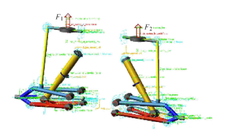
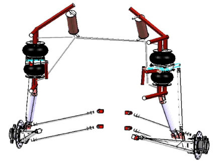
如图 5 和图 6 所示,所研究的全地形车前悬架为双横臂式独立悬架,左右两侧各有上下两个气室,上下两个气室通过摇臂支座相互连接,所述摇臂支座一端与车架铰接另一端与推杆铰接. 当悬架跳动时,单侧推杆推动摇臂带动上下两个气室做压缩、拉伸运动. 将左右两侧上下气室的弹性力简化为垂直方向上的合力 $F_1 $ 和 $F_2$.图5
 新窗口打开|下载原图ZIP|生成PPT
图5前悬架动力学模型
Fig.5Dynamics model of front suspension
图6
 新窗口打开|下载原图ZIP|生成PPT
图6前悬架三维模型
Fig.63D model of front suspension
2.2 后悬架模型
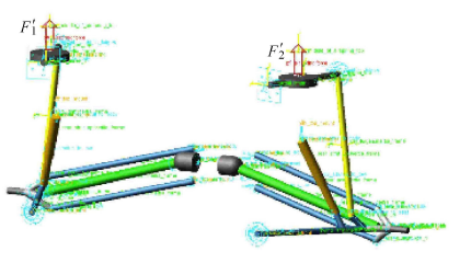
如图 7 和图 8 所示,所研究的全地形车后悬架为斜置单纵臂独立悬架,双气室结构与前悬架一致. 当悬架跳动时,单侧推杆推动摇臂带动上下两个气室做压缩、拉伸运动. 将左右两侧上下气室的弹性力简化为垂直方向上的合力 $F'_1 $ 和 $F'_2$.图7
 新窗口打开|下载原图ZIP|生成PPT
图7后悬架动力学模型
Fig.7Dynamics model of rear suspension
图8
 新窗口打开|下载原图ZIP|生成PPT
图8后悬架三维模型
Fig.83D model of rear suspension
2.3 机械气体耦合整车模型
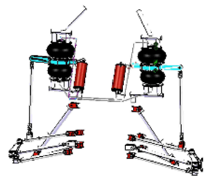
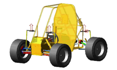
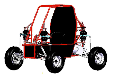
如图 9 和图 10 所示为整车机械气体耦合动力学模型与整车三维模型,以下为搭载上述交叉型双气室空气互联悬架的全地形车参数表.图9
 新窗口打开|下载原图ZIP|生成PPT
图9整车机械气体耦合模型
Fig.9Mechanical-gas coupling model of vehicle
图10
 新窗口打开|下载原图ZIP|生成PPT
图10整车三维模型
Fig.103D model of vehicle
3 机械-气体动力学联合仿真
3.1 仿真模型
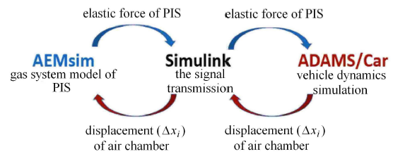
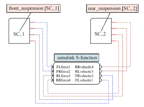
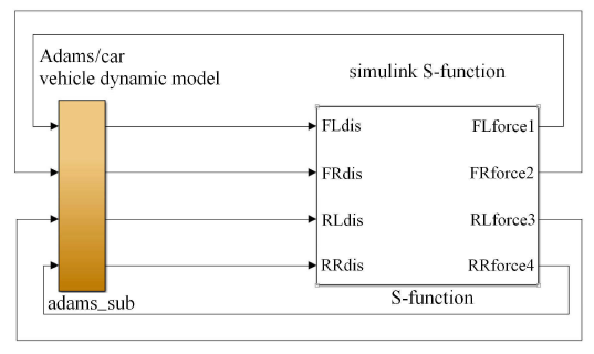
如图 11 联合仿真示意图,将交叉互联悬架气体耦合模型与整车动力学模型通过 Simulink 作为信号传输中介进行通信. ADAMS/Car 整车动力学模型的输入变量为 AMEsim 气体耦合模型中的各悬架弹簧力,输出变量为各悬架摇臂与双气室连接点处位移信号 $\Delta x_{i}$;AMEsim 气体耦合模型的输入变量为各悬架摇臂与双气室连接点处位移信号 $\Delta x_{i}$,输出变量为各悬架弹簧力. 从而建立了完整的机械-气体耦合多自由度动力学联合仿真模型.图11
 新窗口打开|下载原图ZIP|生成PPT
图11联合仿真流程图
Fig.11The flow chart of co-simulation
图12
 新窗口打开|下载原图ZIP|生成PPT
图12AMEsim 气体系统模型与 Simulink 交互
Fig.12The AMEsim gas system model interacts with Simulink
图13
 新窗口打开|下载原图ZIP|生成PPT
图13ADAMS/Car 动力学模型与 Simulink 交互
Fig.13The ADAMS/Car dynamics model interacts with Simulink
3.2 J 型高速过弯仿真试验
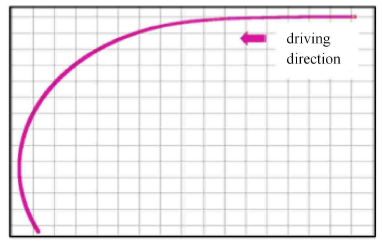
试验工况:从初始位置开始,直行 3s,紧接着前轮转角在 4s 内左转 20$^\circ$,然后固定前轮转角保持 8s,试验共用时 15s,整个过程保持车速 50km/h. 图 14 和图 15 为试验过程轨迹.图14
 新窗口打开|下载原图ZIP|生成PPT
图14仿真试验轨迹图
Fig.14Track of simulation experiment
图15
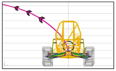 新窗口打开|下载原图ZIP|生成PPT
图15仿真实验后视图
Fig.15Back view of simulation experiment
试验对象: ① 搭载交叉型双气室互联悬架 (PIS) 的全地形车,互联管路直径 10mm.
② 搭载双气室非互联悬架 (UN-PIS) 的全地形车,各连接管径参数设置为 0.001mm,以实现物理意义上的管路不连通.
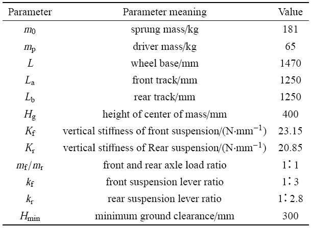
③ 搭载传统螺旋弹簧悬架 (HS) 全地形车,其悬架弹簧刚度和杠杆比已调节至与第一组试验对象完全相同,参数见表 2.
Table 2
表 2
表 2全地形车初始参数
Table 2
 |
新窗口打开|下载CSV
整车气路系统初始参数与全地形车初始参数上文中已给出. 通过测取两组试验中全地形车侧倾角随时间的变化曲线,对交叉型双气室空气互联悬架全地形车在 J 型高速过弯中的侧倾特性进行评价.
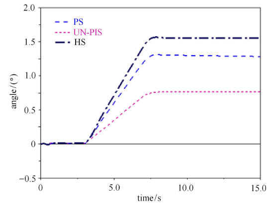
如图 16 中 PIS 与 UN-PIS 曲线对比,在 7.0s 至15.0s 之间的稳态过程中,UN-PIS 曲线位于下方,其稳态倾角为 0.7$^\circ$,而 PIS 全地形车稳态侧倾角为 1.3$^\circ$. 验证了 1.2 节结论,即气体系统状态相同的双气室互联悬架 PIS 与非互联悬架 UN-PIS,前者侧倾角刚度远小于后者. 亦表明 PIS 系统在正常运行状态下,若切断互联管路,会形成 UN-PIS 非互联状态,使悬架刚度瞬间大幅上升,平顺性瞬间变差. 在整个试验过程中,PIS 与 UN-PIS 全地形车各部分悬架上气室压强变化见图 17.
图16
 新窗口打开|下载原图ZIP|生成PPT
图16PIS、UN-PIS 和HS 侧倾角变化曲线
Fig.16Roll angles of PIS, UN-PIS and HS
图17
 新窗口打开|下载原图ZIP|生成PPT
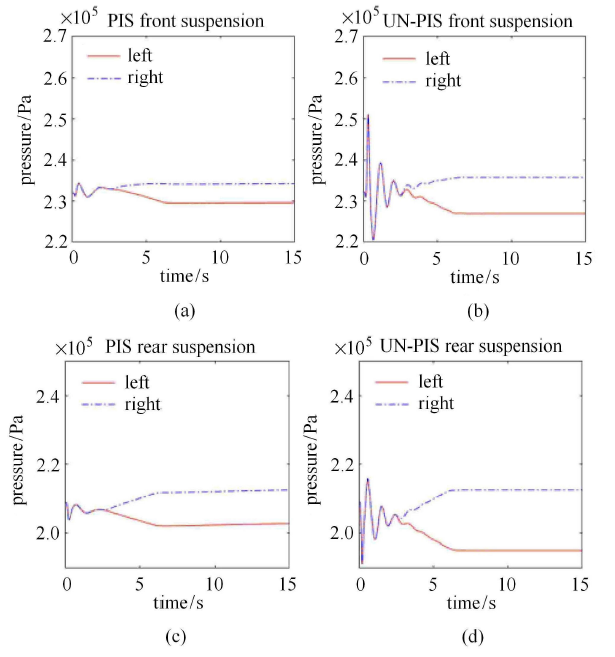
图17PIS 与 UN-PIS 全地形车各气室压强变化
Fig.17Pressure variation in each chamber of PIS and UN-PIS all-terrain vehicles
如图 17(a) 和图 17(b) 分别为 PIS 与 UN-PIS 前悬架左右两侧上气室内压强变化,前悬架气室初始压强为 2.32$\times$10$^5$Pa,在第 3s 之后的左转过程中,全地形车车身向右侧倾,PIS 互联悬架左右两侧上气室分别受拉力和压力,稳态压强分别为 2.28$\times$10$^5$Pa 和 2.35$\times$10$^5$Pa;UN-PIS 非互联空气弹簧由于侧倾角刚度大于 PIS 系统,提供更大的侧倾支撑,其左右两侧上气室稳态压强分别 为2.26 $\times$ 10$^5$Pa 和 2.36 $\times$ 10$^5$Pa;图 17(c) 和图 17(d) 为PIS 与 UN-PIS 后悬架 左右两侧上气室内压强变化,其趋势与前悬架相同,不予赘述.
如图 16 中 PIS 与 HS 曲线对比,PIS 全地形车稳态侧倾角为 1.3$^\circ$,而 HS 全地形车稳态侧倾角为 1.6$^\circ$. PIS 系统较 HS 系统稳态侧倾角降低约 18%.验证了 1.2 节结论,即具有相同垂向刚度的 PIS 与 HS 系统,前者能够提供更多的侧倾角刚度. 且由此推知,在保证提供相同的侧倾角刚度前提下,PIS 系统较传统螺旋弹簧 HS 系统能大幅降低偏频,提高全地形车平顺性.
3.3 气体系统敏感度分析
上述两部分试验研究了初始气体状态相同的双气室非互联悬架与互联悬架,垂向刚度相同的互联悬架与传统螺旋弹簧悬架. 本节对气路系统中影响动态侧倾特性的相关因子包括连接管路管长、管径、附加气室容积进行敏感度分析,仿真工况与前文试验等同.3.3.1 管长敏感度分析
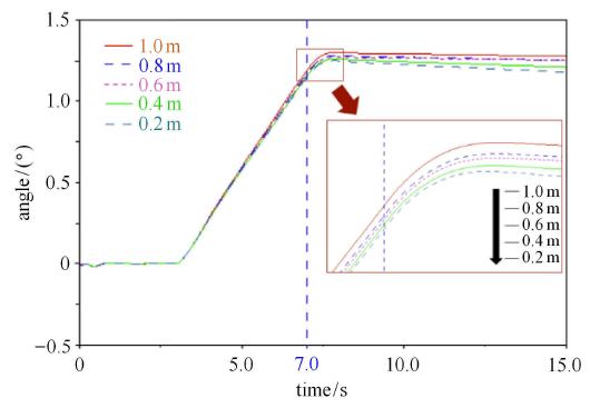
如图 18 所示管长敏感度分析,随管长从1.0m 至 0.2m 以 0.2m 为梯度的逐步减小,稳态侧倾角从 1.30$^\circ$ 逐步降低至 1.20$^\circ$,整体降幅为 0.1$^\circ$.表明管长在小于 1.0m 的长度范围内,连接管路越短,侧倾刚度越大,但影响程度较小.
图18
 新窗口打开|下载原图ZIP|生成PPT
图181.0m 至 0.2m 管长分析
Fig.18Pipe length analysis from 1.0m to 0.2m
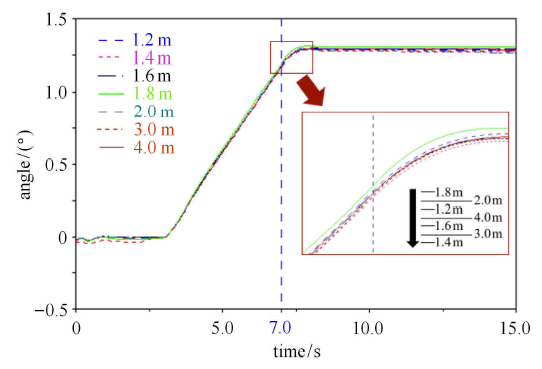
如图 19,随着管长从 1.2m 增大至 4.0m,8 组实验曲线非常接近,最大稳态侧倾角 1.30$^\circ$,最小稳态侧倾角 1.27$^\circ$,变化幅值仅为 0.03$^\circ$,变化量为 2%,可认为影响极其微弱,同时呈现出随管路增长,稳态侧倾角趋于定值的趋势.
图19
 新窗口打开|下载原图ZIP|生成PPT
图191.2m 至 4.0m 管长分析
Fig.19Pipe length analysis from 1.2m to 4.0m
由于互联管路的层流特性,管路产生的阻力与管长成正比,与管径的四次方成反比[32]. 因此,当管径一定时,且由于空气动态黏度较小,一定范围内管道长度变化引起的阻尼力较小. 从而当管路长度在 0.2m 至 4.0m 整体区间变化过程中,侧倾角刚度变化微弱.
管路越短,气体在管路中摩擦产生的阻力越小,当管路从初始的 0.2m 逐步增大至 1.0m 过程中,气体与管路摩擦引起阻力逐步开始产生作用,气体能量损耗,使得侧倾角刚度逐步减小,稳态侧倾角逐步增大.
当管长大于 1.0m 并继续增长至 4.0m 的过程中,随管长增大,气体与管路摩擦阻力的影响效果较初期影响效果相比逐步降低,且与气囊和附加气室容积引起的悬架刚度变化相比十分微弱,从而使悬架稳态侧倾角趋于定值.
但由于全地形车实际空间所限,单根管长基本处于小于 1.0m 的范围,从而全地形车空气互联悬架气体管路长度的选取原则为:在有限长度内,管长应取较小值,有利于提升全地形车侧倾角刚度.
3.3.2 管径敏感度分析
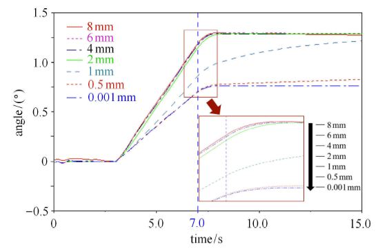
如图 20 所示管径敏感度分析,管径从 8mm 至 0.001mm 逐步减小过程中,稳态侧倾角从 1.30$^\circ$降低至 0.75$^\circ$. 管路由 8mm 降低至 4mm 过程中,稳态侧倾角呈现逐步降低趋势,但变化微弱,管径在 2mm,1mm,0.5mm 至 0.001mm 变化的过程中,稳态侧倾角共降低 42%. 表明管径越小,系统越趋近于非互联 UN-PIS 状态,侧倾角刚度越大,但只在管径减小的末端 2mm 范围内产生刚度突变.
图20
 新窗口打开|下载原图ZIP|生成PPT
图208mm至0.001mm管径分析
Fig.20Pipe diameter analysis from 8mm to 0.001mm
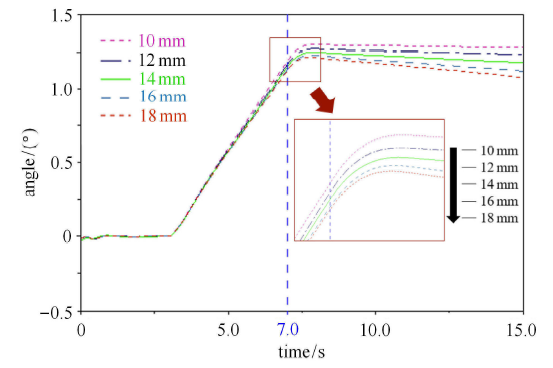
如图 21,管径从 10mm 以 2mm 为梯度增大至 18mm 过程中,稳态侧倾角逐步降低,但总变化量仅为 0.1$^\circ$. 表明管径存在一个临界值 (该例中临界值处于为 8$\sim $10mm 范围内),若管径小于该临界值,管径越小,管径引起的气体流通阻力越大,侧倾角刚度越大,当管径减小至趋于 0 则形成非互联 UN-PIS 状态,使悬架刚度瞬间提升,平顺性恶化. 若管径大于该临界值,管径越大气体流通越顺畅,气体局部湍流引起的损耗越小,使侧倾角刚度小幅度提升.
图21
 新窗口打开|下载原图ZIP|生成PPT
图2110mm至18mm管径分析
Fig.21Pipe diameter analysis from 10mm to 18mm
实际管径选取不可过小,否则在高频工况下管径较小引起动侧倾角刚度过大,不足以发挥互联效果. 同时管径选取不可过大,管径可视为气路联通的大门,只要充分发挥管路联通作用即可,管径选取过大会产生管路对全地形车的底盘空间占用问题. 因此,实际管径可在稍大于管径临界值处进行选取,既保证了气体流通顺畅,又使全地形车侧倾特性处于较佳状态.
3.3.3 附加气室容积敏感度分析
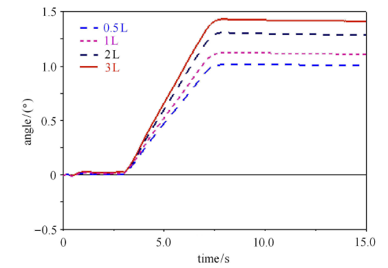
如图 22 所示,附加气室容积敏感度分析,附加气室容积由 3L 减小至 0.5L 的过程中,稳态侧倾角不断减小. 由前文推导易知,附加气室容积减小,会造成交叉互联悬架侧倾角刚度增大,进而产生图中所示变化规律. 但较大的附加气室容积可以得到较软的悬架垂向刚度特性,有利于提升车辆平顺性,故在实际附加气室容积选取时需结合侧倾特性、平顺性与空间占用问题综合考虑.
图22
 新窗口打开|下载原图ZIP|生成PPT
图220.5L 至 3L 附加气室容积分析
Fig.22Volume analysis of additional air chamber from 0.5L to 3L
4 结论
(1) 由悬架刚度理论推导,初始气体状态相同前提下,PIS 垂向刚度和侧倾角刚度均不及 UN-PIS,但等垂向刚度的 PIS 与 HS,前者侧倾角刚度大于后者.(2) 通过仿真试验证明,若切断互联管路,会形成 UN-PIS 非互联状态,使悬架刚度瞬间大幅上升,平顺性瞬间变差;具有相同垂向 刚度的 PIS 与 HS 系统,PIS 系统的稳态侧倾角较 HS 降低 18%,前者能够提供更多的侧倾角刚度,提升了高速侧倾特性. 推论:在保证相同的侧倾刚度前提下,PIS 系统较传统螺旋弹簧系统能大幅降低偏频,提高全地形车平顺性.
(3) 气体系统的敏感度分析发现,互联管路管长越小,越有利于提升全地形车侧倾特性;存在临界管径,管径小于或大于该值时,均会小幅度提升侧倾特性,实际管径可在稍大于管径临界值处进行选取;附加气室容积越小,侧倾角刚度越大,但实际附加气室容积选取需结合侧倾特性、平顺性与空间占用问题综合考虑.
参考文献 原文顺序
文献年度倒序
文中引用次数倒序
被引期刊影响因子
[本文引用: 1]
[本文引用: 1]
DOIURL [本文引用: 1]
DOIURL [本文引用: 1]

A new adaptive vehicle suspension control method is presented that adjusts the controller parametrization to the current driving state and thereby enables to significantly enhance ride comfort while the dynamic wheel load and the suspension deflection remain within safety critical bounds. To this end, the adaptive controller structure dynamically interpolates between differently tuned linear quadratic regulators governed by the dynamic wheel load and the suspension deflection. The stability of the adaptive controller structure is analyzed by means of a common Lyapunov function approach taking into account the nonlinear damper characteristic of the suspension system. In order to provide a realistic framework for the controller design and the performance analysis, a quarter-car test rig based on an all-terrain vehicle suspension that has been equipped with an electrical linear motor to realize an active suspension system, is employed as testbed for the study. On this test rig, the significant performance of the adaptive control concept is successfully validated in a comparison to benchmark suspension controllers.
DOIURL [本文引用: 1]
The work aims to study the performance of suspension systems for off-road vehicles. Three type of suspensions - passive, hybrid semi-active and Linear Quadratic Regulator (LQR) active suspension systems - are presented using half-car model. These systems are compared in terms of ride quality, handling, road holding and ability to support vehicle static weight through transient and statistical analyses. Results indicate the responses of the proposed LQR active system to random road excitation relative to the passive system are better than the hybrid semi-active system in terms of the criteria mentioned above.
DOIURL [本文引用: 1]
[本文引用: 1]
[本文引用: 1]
[本文引用: 1]
[本文引用: 1]
[本文引用: 1]
DOIURL [本文引用: 1]
DOIURL [本文引用: 1]
DOIURL [本文引用: 1]
[本文引用: 1]
[本文引用: 1]
DOIURL [本文引用: 1]
DOIURL [本文引用: 1]
[本文引用: 1]
[本文引用: 1]
URL [本文引用: 1]
URL [本文引用: 1]
[本文引用: 1]
[本文引用: 1]
[本文引用: 1]
[本文引用: 1]
DOIURL [本文引用: 1]
Carbody tilting is used in railway vehicles to reduce the exposure of passengers to lateral acceleration in curves, allowing these to be negotiated at higher speeds with the same level of comfort. This, however, requires a rather complex actuation system that increases vehicle weight and reduces space for passengers.
This paper introduces a new concept that provides a limited amount of carbody tilt using hydraulic actuation. The device consists of interconnected hydraulic actuators attached to the carbody and bogies, replacing the passive anti-roll bar used in railway vehicles and in addition permitting active tilt control.
Three control strategies for the active hydraulic suspension are proposed, and the regulator gains are defined using Genetic Algorithm optimisation, based on numerical simulation of the running behaviour of the actuated railway vehicle in a high-speed curve. Finally, the performance of the actuated vehicle is assessed on the basis of numerical simulations, showing it is possible to increase significantly the vehicle's running speed in fast curves compared with a vehicle equipped with passive suspension. (C) 2014 Elsevier Ltd.
[本文引用: 1]
[本文引用: 1]
DOIURL [本文引用: 1]
DOIURL [本文引用: 1]
DOIURL [本文引用: 1]
This paper extends recent research on vehicles with hydraulically interconnected suspension (HIS) systems. Such suspension schemes have received considerable attention in the research community over the last few years. This is due, in part, to their reported ability to provide stiffness and damping rates dependent on the suspension mode of operation (i.e. the bounce, roll, pitch or articulation of the unsprung masses relative to the sprung mass), rather than relying on the stiffness and damping characteristics of the single wheel stations. The paper uses a nine-degrees-of-freedom (DOF) vehicle model and simulations of a fishhook manoeuvre to assess the handling performance of a vehicle when it is fitted with: (a) a conventional independent suspension, and (b) an HIS. In the case of the latter, the fluid subsystem is modelled using a nonlinear finite-element approach, resulting in a set of coupled, first-order nonlinear differential equations, which describe the dynamics of the integrated mechanical-hydraulic vehicle system. The simulation results indicate that, in general, the HIS-equipped vehicle possesses superior handling, as measured by the sprung mass roll angle, roll rate, roll acceleration, lateral acceleration and the vehicle's Rollover Critical Factor. The potential effects of the suspension set-up on ride performance are also considered by studying the transient response when one side of the vehicle traverses a half-sine bump. The obtained results are then discussed, and it is shown that they are consistent with previous findings, both by the authors and other researchers. The presented work outlines an alternative approach for studying the dynamics of HIS-equipped vehicles, particularly suited to analyses in the time domain.
[本文引用: 1]
[本文引用: 1]
[本文引用: 1]
