 |
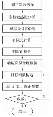
| 图 1 基于响应面方法的模型修正技术流程图Fig. 1 Procedure of model updating technique based on response surface method |
| 图选项 |
1.1 参数选择修正参数必须满足两个条件:①具有不确定性;②结构响应对其敏感.当修正参数太多时,尤其是超过了可测量的结构响应的数量时,优化过程中将出现病态矩阵问题.因此,首先要对修正参数进行敏感性分析,确定少量的重要参数,提高计算精度和速度.1.1.1 敏感性分析敏感性分析能够给出输出变量对输入变量的全局敏感性.正敏感性表示输出变量随着输入变量的增大而增大,负敏感性表示输出变量随着输入变量的增大而减小.本文采用Spearman秩排序法计算相关性系数以确定参数敏感性,该方法同时考虑了输入参数和输出参数的变化范围.1.1.2 重要度分析重要度分析用来确定各输入参数对选定的输出参数的影响,从而确定各输入参数的重要程度.假设输出变量与输入变量之间存在线性或二次关系,利用R2准则来判定参数的重要度:

式中,i为采样点;N为总采样点个数;yi为在第i个采样点的输出变量值;y^i为在第i个采样点的回归值;y-为所有yi的算术平均值.R2越接近1,表明选定的输入参数越重要,越接近0,表明该参数可从修正参数集中去掉,在有限元计算时作为常数.1.2 试验设计方法响应面是对采样点的拟合,因此采样点的选择很大程度上决定了响应面的准确性和计算效率.采样点少则导致响应面准确性差,采样点多则导致计算效率低.在实际应用中,采样点是利用DOE确定的.本文采用的DOE方法是常用的中心复合设计法,该方法能够构造出简单的多项式型响应面.CCD采用正交表进行试验设计以确定选定参数的采样点.常用的CCD方法有3种:外切中心复合设计、嵌套中心复合设计以及面心立方设计.经典的CCD方法包含3部分:①析因部分:一个立方体的2k顶点或这些析因点的一部分;②带有参数α的2k个星点;③中心点.该方法是一种5水平部分析因设计方法:(-α,-1,0,1,+α)或(-1,-1/α,0,1/α,1).当星点处于设计空间每个面上时,CCD从5水平退化为3水平:(-1,0,1).1.3 响应面回归分析响应面的类型对分析结果影响重大.不同的响应面可用于不同的应用情况.在与结构动力学相关的模型修正中,多项式型响应面是常用的响应面类型,该类响应面计算简单且精度较高.本文采用二次多项式响应面,计算公式如下:

其中,β0,βi,βij为回归系数;y为响应面;x为输入变量.采样点必须大于等于多项式的项数.当采样点大于多项式的项数时,式(2)为超定方程,需要利用回归技术对响应面进行拟合.在这种情况下,响应面通常不可能在每个样本点得到精确解.最小二乘拟合常被用于构造响应面.在利用响应面进行结果估计和模型修正之前,必须对响应面的拟合度进行检验.R2准则再次用来检验响应面拟合度.R2越接近于1,表明响应面拟合度越高,利用响应面估计得到的计算结果也就越准确.1.4 目标函数构造与优化分析在进行与结构动力学相关的模型修正时,常常利用结构的振动响应特性来构造目标函数.本文利用结构的模态频率来构造目标函数,并利用多目标函数遗传优化算法(MOGA,Multiple Objective Genetic Algorithm)进行优化分析.MOGA的流程图如图 2所示,主要包括以下步骤:
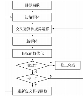 |
| 图 2 MOGA流程图Fig. 2 Procedure of MOGA |
| 图选项 |
1) 创建初始群体;2) 利用交叉运算和变异运算创建新群体;3) 利用新群体更新设计点,计算目标函数并检验其收敛性,若满足则修正完成,否则进入下一步;4) 检查停止准则,若不满足则回到第2)步继续迭代,若满足则停止,迭代失败,重新定义目标函数,重新进行模型修正.2 案例分析案例分析对象为特制的菊花链电路PCB,尺寸为203 mm×140 mm×1.6 mm.初始的材料属性如表 1所示.
表 1 PCB初始材料属性Table 1 Initial material properties of PCB
| 参数 | 初始值 | 参数 | 初始值 |
| Ex/GPa | 18.7 | μxz | 0.18 |
| Ey/GPa | 16.7 | Gxy/GPa | 3.28 |
| Ez/GPa | 7.4 | Gyz/GPa | 2.4 |
| μxy | 0.13 | Gxz/GPa | 2.4 |
| μyz | 0.42 | ρ/(kg·m-3) | 1 836 |
表选项
2.1 模态试验采用固定加速度传感器,移动力锤的方法对PCB进行自由模态试验,共35个测试点(7×5),试验示意图和PCB测试点分布如图 3所示.
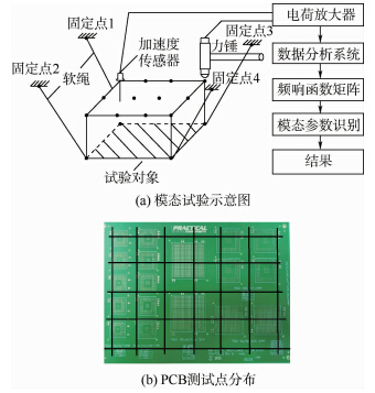 |
| 图 3 试验设置Fig. 3 Test setup |
| 图选项 |
将测得的加速度频响函数转换为速度频响函数,如图 4所示.利用模态指示函数(MIF,Mode Indicate Function)、稳定图(stabilization diagram)和全局时域复指数法提取共振频率和振型.试验振型的MAC(Modal Assurance Criterion)值如表 2所示.从表 2可以看出,测试点数量足够多,振型之间相互独立.试验模态频率的结果如表 3所示.从表 3可以看出,模型修正前的前6阶频率误差最大为7.7%,最小为3.3%.
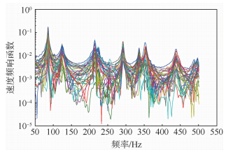 |
| 图 4 速度频响函数Fig. 4 Mobility |
| 图选项 |
表 2 试验振型的MAC值Table 2 MAC values of test modes
| 模态阶数 | 1 | 2 | 3 | 4 | 5 | 6 |
| 1 | 1 | 0 | 0.03 | 0 | 0 | 0.01 |
| 2 | 0 | 1 | 0 | 0 | 0 | 0.01 |
| 3 | 0.03 | 0 | 1 | 0 | 0 | 0.02 |
| 4 | 0 | 0 | 0 | 1 | 0 | 0 |
| 5 | 0 | 0 | 0 | 0 | 1 | 0.01 |
| 6 | 0.01 | 0.01 | 0.02 | 0 | 0.01 | 1 |
表选项
表 3 修正前后前6阶共振频率对比Table 3 Comparison of first six resonant frequencies before and after model updating
| 模态阶数 | 试验模态频率/Hz | 仿真结果 | |||
| 修正前 | 修正后 | ||||
| 频率/Hz | 误差/% | 频率/Hz | 误差/% | ||
| 1 | 85.4 | 79.663 | -6.7 | 85.208 | -0.2 |
| 2 | 125.4 | 120.73 | -3.7 | 125.52 | 0.0 |
| 3 | 214.9 | 202.58 | -5.7 | 214.54 | -0.2 |
| 4 | 291.6 | 273.25 | -6.3 | 301.07 | 3.2 |
| 5 | 338.8 | 312.58 | -7.7 | 337.85 | -0.3 |
| 6 | 353.4 | 341.88 | -3.3 | 359.4 | 1.7 |
表选项
2.2 有限元分析利用ANSYS对PCB进行有限元建模,采用200个壳单元,边界条件为自由状态.有限元和试验振型的MAC值如表 4所示.表 4中第1行表示试验的前6阶模态,第1列表示有限元计算的前6阶模态.从表 4可以看出,有限元和试验的模态振型相关性较好(对角项均大于0.8),且不同阶振型的独立性较好(非对角项均接近0).
表 4 有限元仿真和试验振型的MAC值Table 4 MAC values of finite element (FE) simulation and test modes
| 模态 | 1 | 2 | 3 | 4 | 5 | 6 |
| FEA1 | 0.94 | 0.04 | 0.05 | 0 | 0 | 0.01 |
| FEA2 | 0.01 | 0.93 | 0.02 | 0 | 0 | 0.03 |
| FEA3 | 0 | 0 | 0.86 | 0.05 | 0 | 0.06 |
| FEA4 | 0 | 0 | 0 | 0.91 | 0.02 | 0.05 |
| FEA5 | 0 | 0 | 0 | 0 | 0.94 | 0 |
| FEA6 | 0 | 0 | 0 | 0 | 0.03 | 0.80 |
表选项
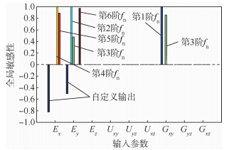
PCB的密度和几何尺寸比较容易测量,且相对变化很小,因此本文将PCB的正交各向异性材料属性(3个弹性模量,3个泊松比,3个剪切模量)作为初始输入(修正)变量,前6阶共振频率和一个自定义变量作为输出变量,自定义变量为前6阶模态频率的残差平方和:

式中,fai为有限元分析频率;fei为试验频率,i为模态阶数.输入参数的敏感性分析如图 5所示.
 |
| 图 5 参数敏感性分析Fig. 5 Parameter sensitivity analysis |
| 图选项 |
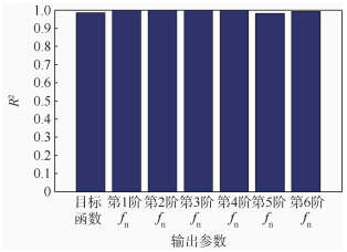
由图 5可以看出,输出变量只对Ex,Ey和Gxy敏感.利用这3个输入变量进行重要度检验,结果如图 6所示.由图 6可以看出,当选择这3个变量为重要参数时,前6阶模态频率和自定义输出变量的R2均接近1,因此将这3个输入参数作为最终的优化参数.利用DOE生成15个试验点(采样点),生成算法为CCD.
 |
| 图 6 参数重要度分析Fig. 6 Parameter importance analysis |
| 图选项 |
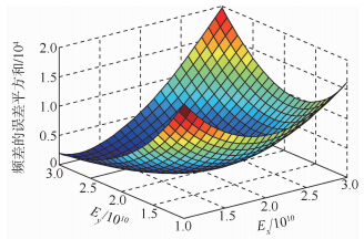
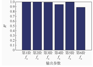
利用2阶多项式拟合出响应面,目标函数和Ex,Ey的响应面如图 7所示.利用R2准则进行响应面的拟合度检验,结果如图 8所示.由图 8可以看出,前6阶共振频率的R2均接近1,因此拟合度较高.
 |
| 图 7 响应面示例Fig. 7 Example of response surface |
| 图选项 |
 |
| 图 8 响应面拟合度检验Fig. 8 Response surface fitness check |
| 图选项 |
PCB的前3阶模态频率常常是最重要的,利用前3阶共振频率构造3个目标函数:

再利用前6阶模态频率残差平方和构造第4个目标函数:

利用MOGA对多目标函数迭代计算,目标是使得4个目标函数最小化.初始样本数为100,每一次迭代生成100组新的样本,迭代算法采用的是遗传基因算法,每一次的变异概率(mutation probability)为0.01,每一次交叉概率(crossover probability)为0.98.设置两种收敛准则:最大允许Pareto比和收敛稳定比.迭代过程如图 9~图 11所示.可以看出,经过6次迭代后4个目标函数都达到了收敛值(第2个目标函数收敛性相对较差),Pareto百分比达到稳定值70%,Stability百分比达到稳定值2%,收敛速度较快.
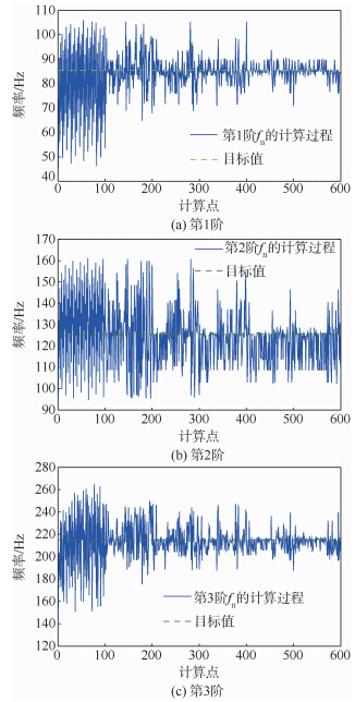 |
| 图 9 前3阶共振频率迭代过程Fig. 9 Iteration processes of first three resonant frequencies |
| 图选项 |
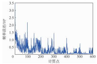 |
| 图 10 第4个目标函数迭代过程Fig. 10 Iteration process of fourth objective function |
| 图选项 |
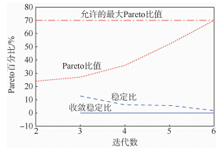 |
| 图 11 两种迭代判据下的收敛过程Fig. 11 Convergence process with two different iterative criteria |
| 图选项 |
修正前后PCB的材料属性如表 5所示.利用修正后的材料属性得到修正后的模态频率如表 3所示.由表 3可以看出,修正后PCB前6阶模态频率的误差最大为3.2%,最小为0.
表 5 修正前后材料属性对比Table 5 Comparison of material parameters before and after updating
| 修正状态 | Ex/GPa | Ey/GPa | Gxy/GPa |
| 修正前 | 18.7 | 16.7 | 3.28 |
| 修正后 | 22.7 | 18 | 3.76< |
表选项
3 结 论本文提出了利用DOE,二次多项式响应面,多目标函数和遗传优化算法对自由边界条件下的PCB进行模型修正的方法,结论如下:1) 在自由边界条件下,Ex,Ey和Gxy对PCB的模态频率影响最大.2) 修正后PCB前6阶模态频率的误差最大为3.2%,最小为0,达到了模型修正的目的.3) 多目标函数修正过程收敛速度较快,可利用已有商业有限元软件直接进行分析,易于工程应用.本文虽然只研究了自由边界条件下裸板的模型修正,但只要选择好适当的修正参数,本文提出的方法也可用于对真实使用条件下安装了元器件的PCB进行模型修正,这也是作者下一步将要研究的内容.
参考文献
| [1] | Baruch M. Optimization procedure to correct stiffness and flexibility matrices using vibration tests[J].AIAA Journal,1978,16(11): 1208-1210. |
| Click to display the text | |
| [2] | Baruch M, Bar Itzhack I Y.Optimal weighted orthogonalization of measured modes[J].AIAA Journal,1978,16(4):346-351. |
| Click to display the text | |
| [3] | Baruch M. Methods of reference basis for identification of linear dynamic structures[J].AIAA Journal,1984,22(4):561-564. |
| Click to display the text | |
| [4] | Berman A. Optimal weighted orthogonalization of measured modes-comment[J].AIAA Journal,1979,17(8): 927-928. |
| Click to display the text | |
| [5] | Berman A, Nagy E J.Improvement of a large analytical model using test data[J].AIAA Journal,1983,21(8):1168-1173. |
| Click to display the text | |
| [6] | Fox R, Kapoor M,Rate of change of eigenvalues and eigenvectors[J].AIAA Journal,1968,6(12)2426-2429. |
| Click to display the text | |
| [7] | Mottershead J E, Friswell M I.Model updating in structural dynamics:a survey[J].Journal of Sound and Vibration,1993,167(2) :347-375. |
| Click to display the text | |
| [8] | Friswell M I, Mottershead J E.Finite element model updating in structural dynamics[M].Dordrecht:Kluwer Academic Publishers,1995:158-256. |
| Click to display the text | |
| [9] | Natke H G, Lallement G,Cottin N.Properties of various residuals within updating of mathematical models[J].Inverse Problems in Engineering,1995,1(4)329-348. |
| Click to display the text | |
| [10] | Khodaparast H H, Mottershead J E,Friswell M I.Perturbation methods for the estimation of parameter variability in stochastic model updating[J].Mechanical Systems and Signal Processing,2008,22(8):1751-1773. |
| Click to display the text | |
| [11] | Shahverdi H, Mares C,Wang W,et al.Clustering of parameter sensitivities:examples from a helicopter airframe model updating exercise[J].Shock and Vibration,2009,16(1):75-88. |
| Click to display the text | |
| [12] | Mottershead J E, Link M,Friswell M I.The sensitivity method in finite element model updating:a tutorial[J].Mechanical Systems and Signal Processing,2011,25(7):2275-2296. |
| Click to display the text | |
| [13] | Ren W X, Fang S E,Deng M Y.Response surface-based finite-element-model updating using structural static responses[J].Journal of Engineering Mechanics,2010,137(4):248-257. |
| Click to display the text | |
| [14] | Ren W X, Chen H B.Finite element model updating in structural dynamics by using the response surface method[J].Engineering Structures,2010,32(8):2455-2465. |
| Click to display the text | |
| [15] | Zhou L R, Yan G R,Ou J P.Response surface method based on radial basis functions for modeling large-scale structures in model updating[J].Computer-Aided Civil and Infrastructure Engineering,2013,28(3):210-226. |
| Click to display the text | |
| [16] | Pitarresi, J M.Modeling of printed circuit cards subject to vibration[C]//IEEE Proceedings of the Circuits and Systems Conference.Piscataway,NJ:IEEE,1990,3:2104-2107. |
| Click to display the text | |
| [17] | Pitarresi J M, Celetka D,Coldwel R,et al.The smeared properties approach to FE vibration modeling of printed circuit cards[J].ASME Journal of Electronics Packaging,1991,113(3)250-257. |
| Click to display the text | |
| [18] | Pitarresi J M, Primavera A.Comparison of vibration modeling techniques for printed circuit cards[J].Journal of Electronic Packaging,1992,114(4)378-383. |
| Click to display the text | |
| [19] | Lim G, Ong J,Penny J.Effect of edge and internal point support of a printed circuit board under vibration[J].ASME Journal of Electronic Packaging,1999,121(2)122-126. |
| Click to display the text | |
| [20] | Deiter A, Baker M.Using analysis to design for drop or other shock environment[J].Sound & Vibration,2000,36(10):26-30. |
| Click to display the text | |
| [21] | Li R S. A methodology for fatigue prediction of electronic components under random vibration load[J]Transactions of the ASME,2001,123(4)394-400. |
| Click to display the text | |
| [22] | Amy R A, Aglietti G S,Richardson G.Sensitivity analysis of simplified printed circuit board finite element models[J].Microelectronics reliability,2009,49(7):791-799. |
| Click to display the text | |
| [23] | Amy R A, Aglietti G S,Richardson G.Accuracy of simplified printed circuit board finite element models[J].Microelectronics Reliability,2010,50(1):86-97. |
| Click to display the text | |
| [24] | 刘孝保,杜平安, 夏汉良,等.一种面向动态分析的PCB板等效建模方法[J].仪器仪表学报,2011,32(4):863-869. Liu X B,Du P A,Xia H L,et al.Dynamic property analysis-oriented PCB equivalent modeling method[J].Chinese Journal of Scientific Instrument,2011,32(4):863-869(in Chinese). |
| Cited By in Cnki (6) | Click to display the text |
