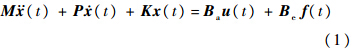
其中,M ∈Rn×n,P∈Rn×n,K∈Rn×n分别为被控结构的质量矩阵、阻尼矩阵和刚度矩阵;
 (t)∈Rn×1,
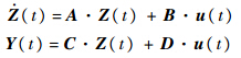
 (t)∈Rn×1,x(t)∈Rn×1分别为被控结构的加速度向量、速度向量和位移向量;矩阵Ba∈Rn×r为驱动器的位置矩阵,表征驱动器的分布,其中r为驱动器的个数;u(t)∈Rr×1为反馈控制力,即控制器的输出力;矩阵Be∈Rn×s为外部载荷作用的位置矩阵,表征外部激励的分布,其中s为外部激励数;F(t)∈Rs×1为外部载荷向量.在振动主动控制领域,一般将以上二阶动力学微分方程转换为一阶状态空间方程.定义状态变量Z(t)=[x T(t),T(t)]T,则式(1)可以表示为如下的一阶状态空间方程,即
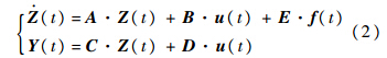
其中
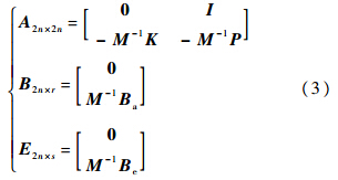
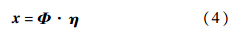
C和D分别为输出矩阵和直接转移矩阵,一般情况下直接转移矩阵D=0,输出矩阵C可以根据要输出的物理量进行选取.由式(3)可以看出,如果系统的自由度n较大时,状态空间方程的维数就会很大,不便于进行控制器的设计和分析.为了便于讨论,对于实际工程系统不直接采用这种状态空间转换,而是采用模态展开的方法得到系统的状态空间方程.由于系统的动力学行为主要由前几阶模态决定,因此利用这种方法可以有效地减少系统的自由度,从而减少计算量,提高计算效率.由结构动力学的知识可知,利用如下的坐标转换:
动力学方程式(1)可以写成模态坐标下的一组常微分方程:
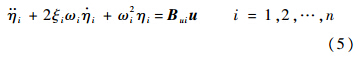
其中,Φ 为系统的模态矩阵,即ΦT MΦ=In×n; Bui∈R1×r为矩阵ΦTBa的第i行.由于外部载荷向量F(t)不影响系统的内部描述,因此本文对其忽略,在系统分析中可以将其作为外部扰动来处理.考虑前q阶模态,
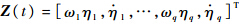 为状态变量,式(5)的状态空间描述可以写为
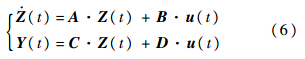
ωi,ξi分别为系统第i阶自然频率和模态阻尼比.为了满足对结构动力响应的要求(在时间t1和t2之间系统的响应不应大于给定值Ycr),即
假定结构的所有状态都是可测的,则可以利用状态反馈控制器对结构的动力学响应进行主动控制,即
其中G为状态反馈控制器,可由不同的设计方法求得,由于本文的重点不在如何求得控制器G,因此本文假定其为已知.由于结构在生产、制造、加工及安装等方面存在各种的不确定性.同时,关于系统的各种参数的试验数据又是有限的,不足以用来确定各不确定性量的概率密度函数.笔者假定结构的各种不确定参数在一区间范围内变化,即
其中m为不确定量的个数.由有限元分析可知被控结构的质量矩阵、阻尼矩阵和刚度矩阵是依赖于不确定参数b的,因此一阶状态空间方程(6)中的传递矩阵A和输入矩阵B均是不确定量b的函数,故考虑不确定性的结构振动主动控制方程可以写为
将式(9)代入式(11)则可得闭环控制系统的状态空间为

由于不确定性的存在,利用名义矩阵求得的控制器施加在结构上时,结构的动力响应并不一定能够满足设计要求(式(8)).也就是说主动控制系统在不确定性因素的影响下,有可能失效(不可靠).因此,有必要分析这种不确定对主动控制系统的影响,对结构振动主动控制系统进行可靠性分析,以便改进控制器的设计提高系统的可靠度. 2 闭环控制系统非概率可靠性度量传统的动力学可靠性分析方法以结构的动力响应首次超越临界值为标志,通常称为首次穿越问题.一般情况下,动力学可靠性分析将系统响应处理为稳态高斯随机过程.如果响应值小于给定的临界值,则系统安全,否则失效.这种可靠性计算方法只适于分析确定系统受到随机激励的情况.本文则从结构的不确定性方面出发,对结构振动主动控制系统进行分析,首先假定在时间[t1,t2]内,系统响应只有1次可能超过临界值,如图 1所示.
 |
| 图 1 系统动力响应穿过阈值的可能次数Fig. 1 Possible times of dynamic response across the threshold |
| 图选项 |
定义如下的极限状态方程:
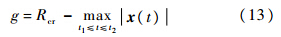
其中,Rcr为闭环控制系统所允许的最大响应;
 为时间[t1,t2]内系统的真实响应的最大值,为了表述简洁,定义S=.当g>0时,系统安全;当g<0时,系统失效;当g=0时,系统处于临界状态.因此,系统的可靠度(系统安全的可能性)可以定义为
由于结构参数的不确定性,闭环控制系统在时间[t1,t2]内真实响应的最大值S也是不确定的,根据第3节中提出的含区间不确定参数的闭环控制系统响应分析方法,可以得到S的区间范围SI.在实际工程中,尤其是航空航天领域的结构振动主动控制系统,设计要求一般也是不确定的,即闭环控制系统所允许的最大响应Rcr也属于区间范围内,即Rcr∈RcrI.这样闭环控制系统非概率可靠性度量就转换为两个区间数之间大小的比较.王晓军等提出一种区间数比较大小的方法[13].在二维空间中,变量S和Rcr的变化空间为变量所围成的面积.这个空间被失效平面(g=0)分为安全域和失效域两部分,如图 2所示.
 |
| 图 2 非概率可靠度计算示意图Fig. 2 Schematic diagram of non-probabilistic reliability calculating |
| 图选项 |
当响应量S小于给定的允许值Rcr时,g>0,即系统是安全的,因此称响应量小于给定的允许值的可能性度量称为结构振动主动控制系统的非概率可靠度,定义为安全域面积与不确定变量所围面积之比,即

相应的结构振动主动控制系统失效的可能性度量可以定义为失效域面积与不确定变量所围面积之比,即

当然如果极限状态方程含有的区间变量大于两个,则区间变量所围成的区域为长方体或超长方体,此时,非概率可靠度可以定义为安全区域的超体积与总体积的比值.当然,如果极限状态方程具有非线性的形式,这种非概率可靠度的定义方法也是适用的.当阈值为某一确定数时,非概率可靠性模型就退化成数轴上长度之比.当在时间[t1,t5]内,系统响应有多次可能超过阈值时,如图 1所示,则时间[t1,t5]内系统的可靠度可以定义为

其中p为系统响应在[t1,t5]内有可能超过给定值的次数.Psi(i=1,2,…,p)的计算可以通过分割时间[t1,t5],使得在每一个时间段内系统只有1次可能超过临界值.如图 1所示,可将时间[t1,t5]分割为[t1,t2],[t2,t3],[t3,t4],[t4,t5]4部分,分别利用上文提出非概率计算方法在相应的时间段内计算系统的可靠度,然后利用式(17)计算总的可靠度. 3 含区间不确定参数的闭环控制系统分析 由前面两节可以看出,在得到闭环控制系统响应的区间后才能对其可靠性进行度量.为了分析闭环控制系统的可靠性,首先要明确不确定性在闭环控制系统中是如何传播的.考虑如式(12)所示的闭环控制系统,首先要找到所有满足状态空间方程(12)的解.很容易看出:当参数B变化时,满足方程的解有无穷多个,这些解组成如下的响应集合:
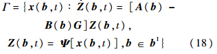
式中
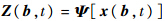 表示系统在模态空间下的响应是物理坐标下响应的函数,系统的真实物理响应可以由模态空间下的响应转换得到. 一般来说,集合Γ是一个难以得到的、非常复杂的区域.在区间数学中,求解如式(18)所示的动力响应实际上就是找到一个区间向量来包含响应集合式(18),也就是说,要寻找响应集合的边界:
其中,

 . 并且
. 并且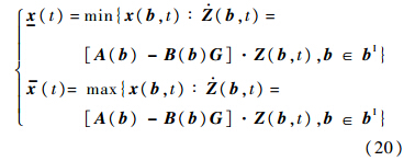
依据区间数学中的表示方法,区间变量bI的均值(名义值或中值)和半径(不确定范围)可以分别表示为
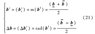
基于区间数学和区间运算,结构参数不确定量b可以分解为确定性部分和不确定部分(名义值和不确定半径):
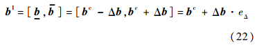
其中eΔ=[-1,1]为单位区间变量.将结构参数b表示为式(23)的形式:

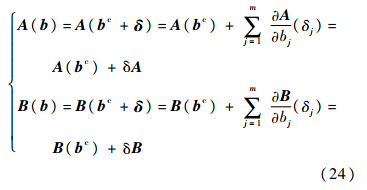
将系统矩阵A(B),B(b)在结构参数b的中心值处展开得
假定系统响应可以表示为
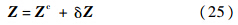
为了表达简洁,式(25)中忽略了时间变量t,由于结构参数的变化为较小的量,因此可以在其均值附近将系统响应进行泰勒展开,即
其中
将方程式(24)、式(25)代入方程(12)可以得到:
展开式(27)并忽略高阶小项,重新整理可以得到:

式(28)有两个未知项,同时有两个方程,利用精细时间积分方法很容易得到响应的均值Zc和不确定量δZ,结合式(26)便可以求出Z,jc.利用区间扩张原理,可以得到系统响应的区间为

其中
将模态空间的响应经过模态矩阵式(4)的变换便可得到系统真实的物理响应,同时利用区间运算,可以得到系统真实物理响应的区间上下界:

其中x,jc可以由Zc,j 经模态变换求得.经过上面的推导,已经得到了系统响应的区间上下界,由式(13)极限状态函数可以看出,要想计算系统的可靠度,需要得到系统响应S=
 在给定的时间[t1,t2]内的区间范围SI.在时间[t1,t2]内,由于系统响应只有1次可能性穿越阈值,因此,定义系统响应S=
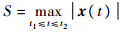 的区间为
的区间为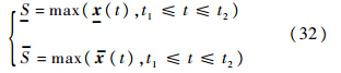
一般情况下上式中的优化问题会在同一时间t′达到.对于系统响应对某一参数特别敏感或者系统不稳定时,上式的优化问题可能不会在同一时间出现,利用上式得到的区间会变窄,计算的可靠度会变小,计算结果会偏向保守,但这不影响该公式的适用. 4 数值算例 4.1 二自由度弹簧-质量-阻尼器振动主动控制系统的可靠性分析考虑如图 3所示的二自由度弹簧-质量-阻尼器系统.
 |
| 图 3 二自由度弹簧-质量-阻尼器振动系统Fig. 3 Two-degrees of freedom mass-spring-damper vibration system |
| 图选项 |
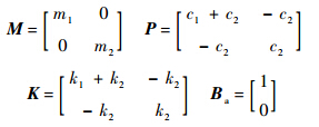
系统参数如下:m1=10 kg,m2=10 kg,k1=20 N/m,k2=15 N/m,c1=3 N·s/m,c1=2 N·s/m .由于制造、加工及安装过程中存在着大量误差,假定系统的参数为区间数,分别为m1I=[7,13]kg,mI2=[7,13]kg,k1I=[17,23]N/m,kI2=[12,18]N/m,c1I=[2,4]N·s/m,cI2=[1,3]N·s/m.控制力作用在质量块m1上,输出量为质量块m2的位移.弹簧质量可以忽略不计,不考虑摩擦等能量损失.根据最小势能原理,可以建立如下的二自由度弹簧-质量-阻尼器系统的有限元方程:

其中质量矩阵、阻尼矩阵、刚度矩阵及驱动器位置矩阵分别如下:
对于自由度较小的系统,可以利用式(3)直接将其转换为状态空间模型:
状态变量为
 ,系统的初始状态为x0=[0 1 1 0]T,控制目标为在t∈[2,∞] 的时间内,系统的响应绝对值不允许超过0.35 m,即
 .根据最优控制理论和名义系统求出的控制器为G=[3 0 1 3]T.图 4给出了开环系统和闭环控制系统输出的名义值,从图中可以看出,名义闭环控制系统是满足控制要求的,即,t∈[2,∞]的时间内,系统的响应绝对值不超过0.35 m.但是由于系统存在不确定性,闭环系统的响应会出现波动,此时,闭环系统的响应就有可能超过给定的阈值.由图 5可以看出,当结构参数发生变化时,闭环控制系统响应下界的绝对值已经超过了0.35 m,也就是说依照名义系统设计的控制器,当真实用于实际时可能会不可靠.
  |
| 图 4 控制前与控制后系统的响应输出Fig. 4 Comparison between responses of open-loop and closed-loop system |
| 图选项 |
 |
| 图 5 区间闭环控制系统响应上下界Fig. 5 Interval bounds of interval closed-loop system |
| 图选项 |
利用本文提出的非概率可靠度分析方法,表 1给出了这种控制器下闭环系统性能的可靠度分析结果.蒙特卡洛(Monte Carlo)分析方法是通过随机抽样方法对不确定结构进行分析的最常用工具,当样本数足够多时,可靠性分析的结果趋于解析解.因此,为了验证本文所提方法的优越性,采用蒙特卡洛方法进行对比.蒙特卡洛仿真模拟中,样本数为10 000,均匀分布抽样.所采用计算机的性能:CPU,Intel®CoreTMi7-2600,3.4 GHz,内存16 GB. 表 1 非概率可靠度分析方法与蒙特卡洛方法比较(弹簧-质量-阻尼器振动系统)Table 1 Comparison between non-probabilistic reliability analysis method and Monte Carlo method (mass-spring-damper vibration system)
| 方法 | 响应最大值的上界/m | 名义值(均值)/m | 响应最大值的下界/m | 计算时间/s | 可靠度/% |
| 蒙特卡洛 | 0.104 4 | 0.208 2 | 0.351 4 | 177.553 | 99.9 |
| 非概率 | 0.053 2 | 0.203 95 | 0.354 7 | 0.147 | 98.4 |
表选项
由表 1可以看出,本文所提方法计算的闭环控制系统的可靠度要低于蒙特卡洛方法得到的可靠度,响应的区间范围也比蒙特卡洛方法得到的区间范围要大,这主要是由于在求解区间响应时,区间运算所带来的区间扩张引起的.这也再次说明了本文所提方法的保守性.从表 1中还可以很清楚地看到蒙特卡洛方法所用时间远远大于非概率可靠度分析方法.本例中系统的失效概率是非常小的,因此蒙特卡洛方法需要大量的抽样才能得到较为准确的结果,而非概率可靠度计算方法则不受样本的影响,只与不确定变量的边界有关,由此也可以说明本文所提出的非概率可靠度分析方法的高效性. 4.2 某型飞机弹舱 振动主动控制系统的可靠性分析为了说明本文所提方法在实际工程中的可应用性,将本文所提方法应用于某型飞机弹舱结构的振动主动控制系统.考虑如图 6所示的某型飞机弹舱,由于此弹舱为一封闭空腔结构,在飞机高速飞行的情况下,外部不稳定气流作用在弹性壁面上,很容易引起结构声的耦合效应,过高的振动响应和声响应会对弹舱内部的设备造成损害,因此对弹性板(图 6中阴影部分)的振动进行主动控制就显得尤为重要.
 |
| 图 6 某型飞机弹舱振动与噪声主动控制模型Fig. 6 Active control of vibration and noise model of an aircraft bomb bay |
| 图选项 |
如图 6所示,5个刚性面和1个弹性面均为铝合金材料,弹性模量E=68 GPa,泊松比μ=0.3,密度ρ=2770 kg/m3,结构阻尼为比例阻尼P=αM +βK ,α=5.5,β=1.8×10⁻⁵.弹性面的厚度h1=1.8 mm,刚性面厚度h2=20 mm.不确定量为弹性板的厚度和模量:分别为h1I=[1.6,2.0]mm 和EI=[66,70]GPa.由于弹性板上安放一个传感器和两个驱动器,因此,该闭环系统为多输入单输出系统.由图 7可以看出,驱动器与传感器均没有放置在弹性板振动模态的节线上,这样就保证了系统的可控性和可观性.控制要求为系统在受到脉冲载荷时,在整个响应时间内传感器位置的振动幅值不能超过5 mm,即
 |
| 图 7 弹性板的前两阶振动模态Fig. 7 The first two vibration modal of elastic plate |
| 图选项 |
弹性板采用四结点壳单元进行有限元划分,网格如图 7所示,400个单元,451个节点,1 353个自由度,因此,采用式(7)建立其主动控制模型的状态空间方程(q=10),选取前10阶振动模态,响应的前10阶频率在表 2中已经给出.利用线性二次型控制器(LQR)最优控制理论,设定相应的加权矩阵,求解得到控制器为
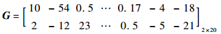
表 2 弹性板的前10阶频率Table 2 The first ten frequencies of elastic plate
| 阶数 | 1 | 2 | 3 | 4 | 5 |
| 频率/Hz | 83.2 | 90.8 | 99.0 | 110.5 | 126.4 |
| 阶数 | 6 | 7 | 8 | 9 | 10 |
| 频率/Hz | 147.1 | 172.4 | 202.4 | 221.7 | 236.7 |
表选项
图 8给出了弹性板控制前后的响应输出.
 |
| 图 8 弹性板控制前与控制后系统的响应输出Fig. 8 Open-loop and closed-loop system responses of elastic plate |
| 图选项 |
图 9给出了考虑不确定时,闭环控制系统响应区间上下界,由图中可以看出闭环控制系统的响应有可能不满足设计要求,即弹性板在传感器位置的振动幅值超过5 mm.将时间段[0,0.1]划分为多个时间段后,只有包含0.01 s的时间段内计算的可靠度不等于1,其他时间段内的可靠度均等于1.表 3中只给出了包含0.01 s的时间段内的可靠度,其与总的可靠度是一致的.与算例1类似,本算例同样采用蒙特卡洛方法与非概率方法进行对比.表 3给出了非概率可靠度分析方法与蒙特卡洛方法的对比,从中可以看出非概率可靠性分析方法的高效性和实用性.
 |
| 图 9 闭环控制系统响应上下界Fig. 9 Interval bounds of interval closed-loop system |
| 图选项 |
表 3 非概率可靠度分析方法与蒙特卡洛方法比较(弹性板)Table 3 Comparison between non-probabilistic reliability analysis method and Monte Carlo method (elastic plate)
方法 | 响应 绝对值的 上界/mm | 名义值 (均值)/ mm | 响应 绝对值的 下界/mm | 计算 时间/s | 可靠度/% |
| 蒙特卡洛 | 4.039 | 4.450 | 5.051 | 27 424.7 | 98.1 |
| 非概率 | 3.473 | 4.288 | 5.108 | 16.439 | 93.0 |
表选项
5 结 论本文基于非概率可靠度分析方法研究了结构振动主动控制系统的可靠性问题.采用区间数量化结构参数的不确定性,建立了闭环控制系统的非概率可靠性指标,并提出了相应的计算方法.1) 与传统概率方法(蒙特卡洛)相比,本文所提出的非概率可靠性分析方法,所需计算时间更短,计算结果更加保守,尤其适用于无法得到不确定量概率信息的复杂大型结构振动主动控制系统.2) 本文基于非概率可靠性分析模型提出了一种解决结构动力学可靠性问题的方法,该方法可以适用于传统的开环动力学系统.3) 本文的研究内容为基于可靠性的振动主动控制器设计提供了新的研究思路,为新型飞机设计过程中采用结构振动主动控制技术提供了理论依据与技术基础.
参考文献
| [1] | Soong T T. Active structural control:theory and practice[M].Harlow,Essex:Longma,1990. |
| [2] | Spencer Jr B F, Sain M K,Kantor J C,et al.Probabilistic stability measures for controlled structures subject to real parameter uncertainties[J].Smart Materials and Structures,1992:294. |
| Click to display the text | |
| [3] | Breitung K, Casciati F,Faravelli L.Reliability based stability analysis for actively controlled structures[J].Engineering Structures,1998,20(3):211-215. |
| Click to display the text | |
| [4] | Battaini M, Breitung K,Casciati F,et al.Active control and reliability of a structure under wind excitation[J].Journal of Wind Engineering and Industrial Aerodynamics,1998,74:1047-1055. |
| Click to display the text | |
| [5] | Crespo L G, Kenny S P.Reliability-based control design for uncertain systems[J].Journal of Guidance,Control,and Dynamics,2005,28(4):649-658. |
| Click to display the text | |
| [6] | Guo S, Li Y.Non-probabilistic reliability method and reliability-based optimal LQR design for vibration control of structures with uncertain-but-bounded parameters[J].Acta Mechanica Sinica,2013,29(6):864-874. |
| Click to display the text | |
| [7] | Guo S. Robust reliability as a measure of stability of controlled dynamic systems with bounded uncertain parameters[J].Journal of Vibration and Control,2010,16(9):1351-1368. |
| Click to display the text | |
| [8] | Guo S. Robust reliability method for non-fragile guaranteed cost control of parametric uncertain systems[J].Systems & Control Letters,2014,64:27-35. |
| Click to display the text | |
| [9] | Venini P, Mariani C.Reliability as a measure of active control effectiveness[J].Computers & Structures,1999,73(1):465-473. |
| [10] | Chen J, Li J.Dynamic response and reliability analysis of non-linear stochastic structures[J].Probabilistic Engineering Mechanics,2005,20(1):33-44. |
| Click to display the text | |
| [11] | Li J, Chen J B.Dynamic response and reliability analysis of structures with uncertain parameters[J].International Journal for Numerical Methods in Engineering,2005,62(2):289-315. |
| Click to display the text | |
| [12] | Crandall S H. First-crossing probabilities of the linear oscillator[J].Journal of Sound and Vibration,1970,12(3):285-299. |
| Click to display the text | |
| [13] | 王晓军, 邱志平,武哲.结构非概率集合可靠性模型[J].力学学报,2007,39(5):641-646. Wang X J,Qiu Z P,Wu Z.Non-probabilistic set-based model for structural reliability[J].Chinese Journal of Theoretical and Applied Mechanics,2007,39(5):641-646(in Chinese). |
| Cited By in Cnki (24) | |
| [14] | 王晓军, 邱志平.结构振动的鲁棒可靠性[J].北京航空航天大学学报,2003,29(11):1006-1010. Wang X J,Qiu Z P.Robust reliability of structural vibration[J].Journal of Beijing University of Aeronautics and Astronautics,2003,29(11):1006-1010(in Chinese). |
| Cited By in Cnki (10) | |
| [15] | 郭书祥, 吕震宙,冯元生.基于区间分析的结构非概率可靠性模型[J].计算力学学报,2001,18(1):56-60. Guo S X,Lü Z Z,Feng Y S.A non-probabilistic model of structural reliability based on interval analysis[J].Chinese Journal of Computational Mechanics,2001,18(1):56-60(in Chinese). |
| Cited By in Cnki (295) | |
| [16] | 郭书祥, 张陵,李颖.结构非概率可靠性指标的求解方法[J].计算力学学报,2005,22(2):227-231. Guo S X,Zhang L,Li Y.Procedures for computing the non-probabilistic reliability index of uncertain structures[J].Chinese Journal of Computational Mechanics,2005,22(2):227-231(in Chinese). |
| Cited By in Cnki (89) |
