Xiaojun Tang1, Peng Chen1, Jianlan Wu2, Ping Wang1, Hao Wang1, Guangli Yang1
(1.School of Information and Communication Engineering, Shanghai University, Shanghai 200040, China;2.College of Information and Communication Engineering, Harbin Engineering University, Harbin 150000, China)
Abstract:
A full metal housing antenna for tablet to cover the GPS and WLAN b/g/a bands (1565-5,2-2484 and 4920-5825 MHz) is presented.The cavity is created by the enclosed volume of PCB and metal housing of the tablet. The cavity is properly excited by a flat exciting element with dimensions of only 36×4 mm2 positioned at an open slot between PCB and metal housing at the tablet's top surface. Among many excited cavity mode resonances, the ones close to the target frequency bands were selected and properly adjusted by adding grounding vias and shorting strip based on the E field distributions. This unique cavity mode excited antenna has measured -6 dB return loss bandwidth of 1 500-1 600 MHz, 2 380-2 500 MHz, 4 580-5 960 MHz and the average efficiencies for all the three bands are over 50%. Therefore, it overcomes the efficiency degradation issue that traditional IFA or monopole antennas are facing at the full metal housing environment.
Key words: cavity full metal housing GPS WLAN tablet
DOI:10.11916/j.issn.1005-9113.16160
Clc Number:TN82
Document Code::A
Fund:
Xiaojun Tang, Peng Chen, Jianlan Wu, Ping Wang, Hao Wang, Guangli Yang. A Novel Tri-band GPS/WLAN Antenna for Tablet with Full Metal Housing[J]. Journal of Harbin Institute of Technology (New Series), 2018, 25(2): 33-40. DOI: 10.11916/j.issn.1005-9113.16160.

Fund Sponsored by the Shanghai "Eastern Scholarship" (Grant No.B.60-D107-14-201) and Shanghai "1000 Plan"(Grant No.S.39-0107-15-204) Corresponding author Guangli Yang, E-mail: guangli.yang@shu.edu.cn Article history Received: 2016-08-29
Contents Abstract Full text Figures/Tables PDF
A Novel Tri-band GPS/WLAN Antenna for Tablet with Full Metal Housing
Xiaojun Tang1, Peng Chen1, Jianlan Wu2, Ping Wang1, Hao Wang1, Guangli Yang1


1. School of Information and Communication Engineering, Shanghai University, Shanghai 200040, China;
2. College of Information and Communication Engineering, Harbin Engineering University, Harbin 150000, China
Received: 2016-08-29
Fund: Sponsored by the Shanghai "Eastern Scholarship" (Grant No.B.60-D107-14-201) and Shanghai "1000 Plan"(Grant No.S.39-0107-15-204)
Corresponding author: Guangli Yang, E-mail: guangli.yang@shu.edu.cn
Abstract: A full metal housing antenna for tablet to cover the GPS and WLAN b/g/a bands (1565-1585, 2412-2484 and 4920-5825 MHz) is presented.The cavity is created by the enclosed volume of PCB and metal housing of the tablet. The cavity is properly excited by a flat exciting element with dimensions of only 36×4 mm2 positioned at an open slot between PCB and metal housing at the tablet's top surface. Among many excited cavity mode resonances, the ones close to the target frequency bands were selected and properly adjusted by adding grounding vias and shorting strip based on the E field distributions. This unique cavity mode excited antenna has measured -6 dB return loss bandwidth of 1 500-1 600 MHz, 2 380-2 500 MHz, 4 580-5 960 MHz and the average efficiencies for all the three bands are over 50%. Therefore, it overcomes the efficiency degradation issue that traditional IFA or monopole antennas are facing at the full metal housing environment.
Key words: cavity full metal housing GPS WLAN tabletcavity full metal housing GPS WLAN tablet
1 Introduction Since Apple Inc. started to use metal frame as a part of antenna on iPhone 4, using metal frame or metal cover in cellular phone and tablet becomes popular. Different from plastic structure, the metal environment has strong coupling, less volume and radiation impact to antenna. The common challenge of using traditional antenna approaches like monopole, loop and IFA (inverted F antenna) under metal environment is how to achieve multiband operation and high efficiency. So, finding new ideas to work better with full metal housing environment with small, low-profile and efficient antenna design to cover GPS and WLAN b/g/a bands is an important research area for both industry and academia.
In the past, there were many WLAN antennas reported in the literature for tablet and laptop applications without GPS band support [1-10]. In Ref.[3], it had a metal back cover, but did not have full side walls around the device and it did not cover GPS band. In Ref.[6], a folded antenna for WLAN application was presented. Its size was only 9.2 mm×6.5 mm×1 mm, but it only covered 2.4 GHz WLAN application and it was not full-metal housing structure. In Refs.[11-14], four small-size antennas for tablet-computer were reported. In Ref.[11], an IFA-based metal-frame antenna for metal-casing tablet computer was presented. The antenna used two inverted F antenna structures to provide a low band and high band. But the antenna was disposed at upper-left corner of metal casing and integrated with the metal frame, it was not a full metal housing structure. In Refs.[15-16], two antennas for GPS and WLAN applications without 4.9/5.8 GHz band, also, the antenna size of 50 mm×50 mm was fairly large. Recently, more and more industrial tablet ID is interested in full-metal design for good looking. However, it will bring great difficulties to the antenna design because large input resistance can be induced by strong coupling between the antenna and the metal housing. In Refs.[17-18], an internal two-PIFA and a direct-fed slot antennas with metal back cover were provided to cover WLAN operation but not GPS.In Ref.[19] was an antenna for GPS/ GLONASS operation with a metal back cover for tablet-computer applications, but it only covers GPS but not WLAN bands. In Ref.[20], an inverted-F GPS and WLAN b/g/a antenna for the metal-casing tablet computer was reported, however, the occupied volume of 25.5 mm×7 mm×4.5 mm was fairly large. Furthermore, the metal cover used in these cases[17-20] does not have full side walls around the device. So, to the best of author's knowledge, there are very limited tri-band solutions to have compact and low-profile antennas for tablet with a full-metal housing to cover GPS and WLAN b/g/a applications.
In this paper, a new antenna design to achieve GPS/WLAN tri-band in a full metal housing environment is proposed. When the metal cover and PCB are connected in the tablet, it works as a closed structure (called "cavity"). Designing antenna for this environment with traditional ways of using loop/IFA/monopole has two big issues. One is large volume and the other is very low efficiency (20% range especially for GPS). Obviously, it is too low to meet the actual requirements. In this paper, a novel antenna is proposed for smaller volume (36×4 mm3) with much higher efficiency (over 50%) than traditional antennas for GPS and WLAN b/g/a applications. Comparing this antenna with the referenced ones in Table 1, this antenna shows advantages over others in terms of size, supported bands and compatibility with full metal environment. The systematic antenna's design and performance will be discussed in the paper.
表 1
Ref. [6] 20×6×0.8 WLAN 2.4/5 Without
Ref. [12] 50×50×1.6 GPS 1.575, WLAN 2.4 Without
Ref. [13] 90×9×5 GPS 1.575 With metal back cover
Ref. [14] 50×9×6 WLAN 2.4/5 With metal back cover
Ref. [15] 21×7.5×4.5 WLAN 2.4/5 With metallic bottom cover
Ref. [16] 25.5×7×4.5 GPS 1.575, WLAN 2.4/5.2/5.8 With metal casing
Proposed (flat 2-D) 36×4 GPS 1.575, WLAN 2.4/4.9/5.8 With full metal housing
Table 1 Comparison between proposed antenna and reference antennas
2 Proposed Antenna and Design Methods The tablet model and antenna structure are shown in Fig. 1. The tablet is in standard size of 246 mm×180 mm×6 mm. For the concept study, it includes metal housing and PCB board. The metal housing includes bottom cover and four side metal walls. The PCB is positioned at top surface where its left, right and top sides are connected to metal housing side walls and the bottom side has an open slot of 9 mm to metal housing. In this design, the antenna is positioned in the left side of the slot area so that the right side can be used for other antenna designs. Our initial study learned that traditional antennas like IFA (inverted F antenna) and monopole antenna have very low efficiency around 20% at GPS band at this environment due to the strong coupling to the metal housing. In order to improve the antenna's efficiency, we proposed the idea of exciting cavity modes created from the enclosed metal structure between PCB and metal housing in this paper. Here, the antenna, actually should called cavity exciting element, is fed from PCB and positioned at the showed location. It is only 36 mm in length and 46 mm away from the metal wall at the left side. Because the resonant frequencies of the cavity modes are determined by the dimensions of the tablet, so, they may not exactly at GPS/WLAN band. In order to tune the resonances, three vias (A, B, C) and a shorting strip (E) are added in the design based on the E field distribution of the different cavity modes. More details on the creation and frequency optimization of the cavity modes are discussed at the later sessions.
Figure 1
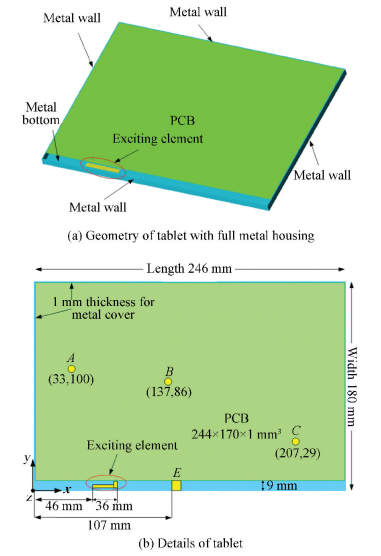 Figure 1 Geometry of tablet and cavity exciting element
 Theoretically, for a given enclosed metal structure such as a 3-D rectangular block shown in Fig. 2. It has the characteristic resonant modes at different frequencies and can be calculated by the formula as follow:
$f = \frac{1}{2}v\sqrt {{{\left( {\frac{m}{a}} \right)}^2} + {{\left( {\frac{n}{b}} \right)}^2} + {{\left( {\frac{p}{c}} \right)}^2}} $ (1)
Figure 2
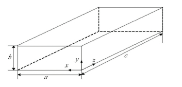 Figure 2 The rectangular resonant cavity
 The formula gives the relationship of frequency and metal cavity geometry where a, b, c is the width, height and length of cavity, and v is the light velocity in the air and m, n=1, 2, 3…, p=0, 1, 2, 3, 4…(integer).Increasing or decreasing size of a, b or c can shift resonant frequency lower or higher. For the typical tablet size of 246 mm×80 mm×6 mm, the cavity's characteristic modes of our interest calculated from the Eq.(1) are listed in Table 2.
表 2
1 1 2 1.477
2 2 3 2.463
3 4 6 4.876
4 4 7 5.381
5 5 7 5.960
Table 2 The characteristic modes for cavity with size 246 mm×180 mm×6 mm when n = 0
From the Fig. 3, we can see that the m=1, p=2 in 1.38 GHz and m=2, p=3 in 2.44 GHz. By setting these parameters into above Eq.(1), and with the parameters a=180 mm, b=6 mm, c=246 mm and n=0. The calculation f was near 1.477 GHz and 2.463 GHz as shown in Table 2, and the mode 1 works at 1.477 GHz close to 1.575 GHz for GPS application, mode 2 works at 2.463 GHz close to 2.45 GHz for WLAN b/g band application, mode 3, 4 and 5 work at 4.9/5.8 GHz band for WLAN a band application. From the Table 2, we can see that the calculated results are higher than the simulated ones, because the cavity modes'E-field distributions are usually irregular.Furthermore, the light velocity v=3×10⁸ m/s used here is higher than that in physical model.
Figure 3
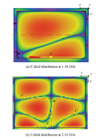 Figure 3 The E-field distributions at 1.38 GHz and 2.44 GHz
 So, these modes are used and properly adjusted to work at related bands. Noticed the return loss between the resonances of mode 3, 4 and 5 are not well enough to cover all the WLAN a band at some frequencies like around 5 GHz, in this design, the cavity exciting element is designed at 1.8 GHz so that its third harmonic resonance is around 5 GHz to work together with three cavity modes for better WLAN a band performance.
Fig. 4 shows the simulated S11 for antenna with and without metal cover. The resonances of antenna with metal cover are very similar as the calculated ones in Table 2, meaning that the cavity modes are properly excited. The S11 of antenna without cover, meaning the resonances from cavity exciting element itself, operates at 1.8 and 5 GHz where 1.8 GHz is not used for this application (possibly for DCS cellular band) but 5 GHz is used to improve the cavity modes' performance at WLAN a band.
Figure 4
 Figure 4 Simulated S11s with and without metal cover
 To determine the length of exciting element, many simulations are studied and eventually the length is set as 36 mm. Fig. 5 showed two cases where exciting element is set as 36 and 45 mm. Both lengths can excite the cavity modes for GPS and WLAN b/g/a bands, there are two reasons that 45 mm was not selected: one is that its 3rd order self-resonance is lower than WLAN a band, the second is that the cavity modes are not excited efficiently as 36 mm's ones. So, eventually exciting element is selected as 36 mm (together with 4 mm vertical part is 40 mm) to best utilize its 3rd order antenna mode at 5 GHz and the excited cavity modes together for GPS and WLAN b/g/a band applications.
Figure 5
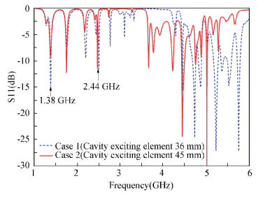 Figure 5 Simulated S11s with cavity exciting element 36 mm and 45 mm
 3 Methods to Adjust Cavity Mode Resonances Due to the size of the tablet, the applicable resonance of cavity modes at 1.38 GHz is exactly at 1.575 GHz for GPS application. Therefore, how to tune this mode to GPS band without affecting other resonances at 2.4 and 5 GHz is important. This can be done by analyzing the each band's E field distribution and changing the field at 1.38 GHz without much impact on the fields of the other two frequencies.
The first method is to add shorting strip in the slot at E′ point as shown in Fig. 1(b). E′ point is determined based the E field distributions of cavity mode m1(1.38 GHz) and mode 2 (2.4 GHz) as shown in Fig. 3. The E′ point is selected at the area with high E field at 1.38 GHz but low E field at 2.4 GHz. As a result, the cavity mode at 1.38 GHz is shifted without affecting the cavity at 2.4 GHz (right for WLAN b/g band). Simulated S11s before and after adding shorting strip at E′ point as shown in Fig. 6 where the m1 cavity mode is shifted from 1.38 GHz to 1.49 GHz while the 2.4 and 5 GHz resonances are almost not affected.
Figure 6
 Figure 6 Simulated S11s without and with E′ strip
 To further tune the cavity mode resonance from 1.49 to 1.575 GHz, the second method is to add grounding vias vertically between PCB and metal cover, similarly, at the high E field area of 1.49 GHz but low E field at 2.4 GHz. The grounding via is shown in Fig. 7 where the top end is connected to PCB and the bottom end is connected to the metal cover. Fig. 8 is E field distribution at 1.49 GHz. There are many options to select grounding via locations, to be most effective in frequency tuning and use less grounding vias, three points are selected at current A', B' and C' locations, they are generally in the high E field region of 1.49 GHz but low E field region of 2.4 GHz as well (Fig. 3(b)).
Figure 7
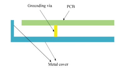 Figure 7 The illustration of grounding via between PCB and metal cover
 Figure 8
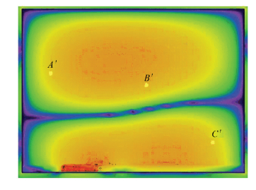 Figure 8 The E-field distribution at 1.49 GHz
 The simulated S11s with and without grounding vias are compared in Fig. 9. It is observed that the cavity resonance at 1.49 GHz is now shifted to the exact GPS frequency band at 1.575 GHz, while the 2.4 and 5 GHz resonances are almost the same. So, by now, a cavity mode excited antenna is completely designed to cover 1.575, 2.45 and 5 GHz frequencies for GPS (1 565-1 585 MHz), WLAN b/g (2 412-2 484 MHz) and a band (4 920-5 825 MHz) applications.
Figure 9
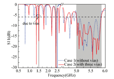 Figure 9 Simulated S11s with and without vias
 4 Experimental Results and Discussions As shown in Fig. 10, it is the photo of the proposed antenna. The measured and simulated S11s are plotted together for comparison in Fig. 11, they have good agreement in general in terms of created cavity modes and resonance frequencies. However, there is a little difference between simulation and experiment.Because the simulation is the result of the ideal environment, so there are some errors with the experiment. Furthermore, the experiment is purely hand-made, so there is also an error in size. Both caused the difference between simulation and experiment as shown in Fig. 11. To define the bandwidth, the S11 with -6 dB standard is selected based on the published papers in the prior art. This proposed antenna has 100 MHz bandwidth (1 500-1 600 MHz) for GPS band, 120 MHz (2 380-2 500 MHz) for WLAN b/g and 1 380 MHz (4 580-5 960 MHz) for WLAN a band. Therefore, the proposed antenna can successfully cover the GPS and WLAN b/g/a required bandwidth (1 565-1 585, 2 412-2 484, 4 920-5 825 MHz).
Figure 10
 Figure 10 Photo of the fabricated antenna
 Figure 11
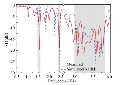 Figure 11 Measured and simulated S11s of proposed antenna
 After S11, the antenna radiation efficiency were measured at standard commercial ETS AMS8500 chamber as in Fig. 12 and Fig. 13 is the photo of measured environment in anechoic chamber. The average measured efficiency of GPS, WLAN b/g and a band is 55%, 54% and 63% respectively, which are considered as efficient in comparison to the typical 40% efficiency requirement in industry. We can see that the efficiency is very high, because the eigenmode theory is a waveguide total reflection, but energy reflection is small, so the efficiency is higher than traditional antennas. Simulation is the ideal state of the environment, so there will be some errors with the experiment. The average measured gain of GPS, WLAN b/g and a band is 5.5, 4 and 6 dBi, respectively, they are reasonable for practical applications.
Figure 12
 Figure 12 Measured peak gains and antenna efficiencies across all the bands of interest
 Figure 13
 Figure 13 Photo of measured environment in anechoic chamber
 The proposed antenna's far-field radiation patterns were also measured at same chamber(Fig. 13). Fig. 14 showed the radiation patterns at 1.57, 2.45, and 5.45 GHz respectively. From Fig. 14(a), (b), and (c), stronger radiation in the +z direction is observed in the x-z plane and y-z planes(elevation plane vertical to the device ground plane), this is reasonable because resonant frequencies are created by the cavity modes which the waveguide is totally reflected in, and the energy is radiated to the +z direction from the slot between PCB and metal side wall. Also, the 1.57 and 2.45 GHz radiation patterns are bi-directional, this is because the EM waves of cavity modes only radiate in very limited space. For the 5.45 GHz band, the scattering pattern could because the radiated modes are co-created by cavity and antenna.
Figure 14
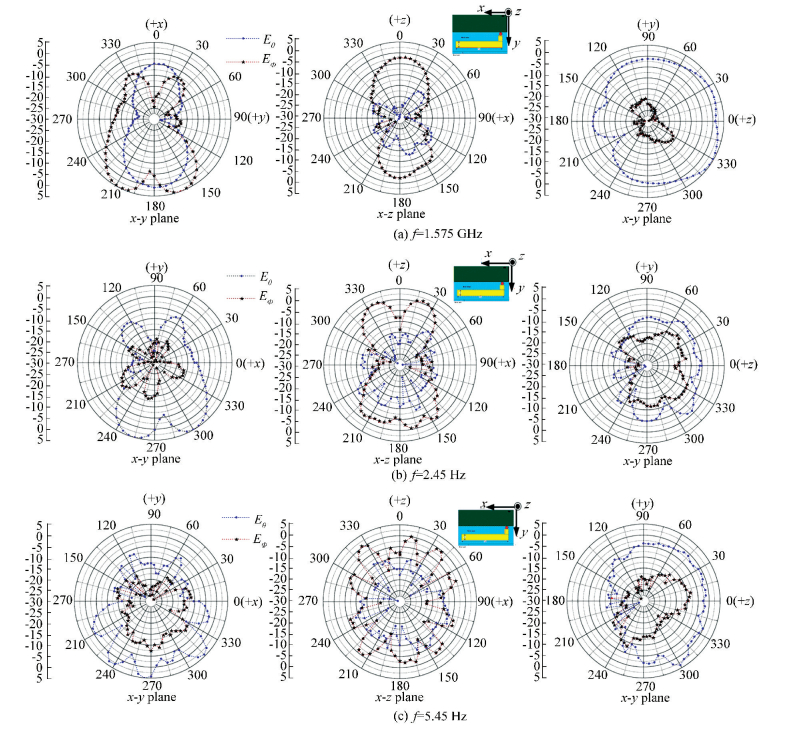 Figure 14 Measured radiation patterns for the proposed antenna
 5 Conclusions A tri-band cavity mode exited antenna at GPS and WLAN b/g/a bands is proposed for tablet with full metal housing. Among the many excited cavity modes, the modes close to the design frequency bands are selected and properly tuned with grounding via and shorting strip based on the E field distributions. The cavity exciting element dimension is set as 36 mm × 4 mm to have efficient cavity mode excitation and create additional resonance band at 5 GHz to enhance the WLAN a band bandwidth. This antenna has measured average efficiency over 50% across the whole three bands. With small, low-profile and efficient performance, it is promising for practical applications for tablet with full metal housing.
References
[1] Su C M, Chen W S, Cheng Y T, et al. Metal-plate shorted T-shaped monopole for internal laptop antenna for 2.4/5 GHz WLAN operation.Antennas and Propagation Society International Symposium. Piscataway:IEEE, 2004, 41: 202-203. DOI:10.1109/APS.2004.1330584 (
 0)
0)[2] Liu H W, Lin S Y, Yang C F. Compact inverted-F antenna with meander shorting strip for tablet WLAN applications. IEEE Antennas and Wireless Propagation Letters, 2011, 10: 540-543. DOI:10.1109/LAWP.2011.2157887 (
 0)
0)[3] Lee C T, Su S W. Very-low-profile 2.4/5.2/5.8-GHz, triband WLAN antenna for laptop-tablet computer with complete metal cover. Microwave and Optical Technology Letters, 2015, 58(1): 225-233. DOI:10.1002/mop.29535 (
 0)
0)[4] Wong K L, Jiang H J, Kao Y C. High-isolation 2.4/5.2/5.8 GHz WLAN MIMO antenna array for laptop computer application. Microwave and Optical Technology Letters, 2012, 55(2): 382-387. DOI:10.1002/mop.27279 (
 0)
0)[5] Sung Y. Compact dual-band antenna for 2.4/5.2/5.8 GHz WLAN service for laptop computer applications. Microwave Optical Technology, 2015, 57(9): 2207-2213. DOI:10.1002/mop.29289 (
 0)
0)[6] Dong Y, Choi J, Itoh T. Folded strip/slot atenna with extended bandwidth for WLAN application. IEEE Antennas and Wireless Propagation Letters, 2016, 16: 673-676. DOI:10.1109/LAWP.2016.2598276 (
 0)
0)[7] Wang H Y, Zheng M. An internal triple-band WLAN antenna. IEEE Antennas Wireless Propagation, 2011, 10: 569-572. DOI:10.1109/LAWP.2011.2158051 (
 0)
0)[8] Liu X, Li Y, Yu W. A compact dual-band WLAN antenna by using a meander line and a lateral L-shaped patch. Proceedings of the 31st International Review of Progress in Applied Computational Electromagnetics (ACES). Piscataway: IEEE, 2015. 1-2. http://ieeexplore.ieee.org/document/7109712/(
 0)
0)[9] Kim T, Kim S J, Byun J, et al. Internal dual-band WLAN antenna for laptop applications. IEEE Antennas and Propagation Society International Symposium. Piscataway: IEEE, 2010. 1-4. DOI: 10.1109/APS.2010.5561725. http://ieeexplore.ieee.org/xpls/abs_all.jsp?arnumber=5561725(
 0)
0)[10] Hsieh S H, Huang D L, Chen F S, et al. A compact inverted-F antenna for dual-band WLAN operations in a mini tablet computer. 2012 IEEE Asia-Pacific Conference on Antennas and Propagation (APCAP). Piscataway: IEEE, 2012. 76-77. DOI: 10.1109/APCAP.2012.6333155. http://ieeexplore.ieee.org/document/6333155/(
 0)
0)[11] Wong K L, Tsai C Y. IFA-based metal-frame antenna without ground clearance for the LTE/WWAN operation in the metal-casing tablet computer. IEEE Transactions on Antennas & Propagation, 2016, 64(1): 53-60. DOI:10.1109/TAP.2015.2503420 (
 0)
0)[12] Wong K L, Tsai C Y. Small-size stacked inverted-F antenna with two hybrid shorting strips for the LTE/WWAN tablet device. IEEE Transactions on Antennas & Propagation, 2014, 62(8): 3962-3969. DOI:10.1109/TAP.2014.2323415 (
 0)
0)[13] Lu J H, Wang Y S. Planar small-size eight-band LTE/WWAN monopole antenna for tablet computers. IEEE Transactions on Antennas & Propagation, 2014, 62(8): 4372-4377. DOI:10.1109/TAP.2014.2327659 (
 0)
0)[14] Wong K L, Chen W J, Kang T W. Small-size loop antenna with a parasitic shorted strip monopole for internal WWAN notebook computer antenna. IEEE Transactions on Antennas & Propagation, 2011, 59(5): 1733-1738. DOI:10.1109/TAP.2011.2122298 (
 0)
0)[15] Liu H W, Qin F, Lei J H, et al. Dual-band microstrip-fed bow-tie antenna for GPS and WLAN application. Microwave and Optical Technology Letters, 2014, 56(9): 2088-2091. DOI:10.1002/mop.28538 (
 0)
0)[16] Daniati N, Nusantara H, Munir A. G-patch dualband printed monopole antenna for GPS and WLAN application. Proceedings of the 7th International Conference on Telecommunication Systems, Services, and Applications (TSSA). Piscataway: IEEE, 2012. 237-240. DOI: 10.1109/TSSA.2012.6366059. http://ieeexplore.ieee.org/document/6366059/(
 0)
0)[17] Su S W. Two-patch-PIFA system with comparable polarization radiation for tablet-computer applications with complete metal back cover. Microwave and Optical Technology Letters, 2015, 55: 149-153. DOI:10.1002/mop.27996 (
 0)
0)[18] Lee Cheng-Tse, Su Saou-Wen, Chen Shu-Chuan, et al. Low-cost, direct-fed slot antenna built in metal cover of notebook computer for 2.4/5.2/5.8-GHz WLAN operation. IEEE Transactions on Antennas and Propagation, 2017, 65(5): 2677-2682. DOI:10.1109/TAP.2017.2679070 (
 0)
0)[19] Su S W. Linearly-polarized patch PIFA for GPS/GLONASS operation for tablet-computer applications. Microwave and Optical Technology Letters, 2014, 57(1): 149-153. DOI:10.1002/mop.28800 (
 0)
0)[20] Tsai C Y, Wong K L. Inverted-F antenna-based on-frame GPS/WLAN antenna for the metal-casing tablet computer. Proceedings of the 2016 10th European Conference on Antennas and Propagation. Piscataway: IEEE, 2016. DOI: 10.1109/EuCAP.2016.7481651. http://ieeexplore.ieee.org/document/7481651/(
 0)
0)